Difference between revisions of "Aufgaben:Exercise 1.7: Coding for Broadband ISDN"
| Line 3: | Line 3: | ||
}} | }} | ||
| − | [[File:EN_Bei_A_1_7_neu.png|right|frame|HDB3 and 1T2B coding | + | [[File:EN_Bei_A_1_7_neu.png|right|frame|HDB3 and 1T2B coding]] |
For conventional ISDN over copper lines the $\rm HDB3$ ("High Definition Bipolar") code is used – see [[Aufgaben:Exercise_1.5:_HDB3_Coding|$\text{Exercise 1.5}$]]: | For conventional ISDN over copper lines the $\rm HDB3$ ("High Definition Bipolar") code is used – see [[Aufgaben:Exercise_1.5:_HDB3_Coding|$\text{Exercise 1.5}$]]: | ||
Latest revision as of 12:14, 10 November 2022
For conventional ISDN over copper lines the $\rm HDB3$ ("High Definition Bipolar") code is used – see $\text{Exercise 1.5}$:
This was derived from the so-called "AMI code",
- is like the latter a pseudo-ternary code,
- but avoids more than three consecutive "$0$" symbols,
- by deliberately violating the stricter AMI coding rule for longer zero sequences.
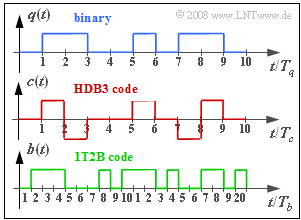
The graph shows the HDB3 encoded signal $c(t)$ resulting from the binary redundancy-free source signal $q(t)$. Since there are no more than three consecutive zeros in the source signal, $c(t)$ is identical to the AMI-encoded signal.
The broadband ISDN planned for the late 1990s was to provide data rates of up to $\text{155 Mbit/s}$ compared with $\text{144 kbit/s}$ of conventional ISDN with two bearer channels and one data channel. To achieve this higher data rate, it was necessary that
- newer technology $\rm (ATM)$ had to be used,
- secondly, the transmission medium had to be changed from copper to fiber optics.
However, since the HDB3-encoded signal $c(t) ∈ \{–1, \ 0, +1\}$ cannot be transmitted by means of light, a second encoding was required.
- The 1T2B code provided for this purpose replaces each ternary symbol with two binary symbols.
- The lower diagram shows an example of the binary signal $b(t) ∈ \{0, 1\}$, which results from the signal $c(t)$ after this 1T2B coding.
- For this exercise, assume that the bit rate of the redundancy-free source signal $q(t)$ is equal to $R_{q} = 2.048 \ \rm Mbit/s$.
- The respective symbol durations of the signals $q(t), c(t)$ and $b(t)$ are denoted by $T_{q}$, $T_{c}$ and $T_{b}$.
- The equivalent bit rate of the pseudo-ternary signal $c(t)$ is $R_{c} = {\rm log_2}(3)/T_{c}$, from which the bit rate $R_{q} = 1/T_{q}$ of the source signal can be used to calculate the relative redundancy of the AMI or HDB3 code:
- $$r_{\rm HDB3} = \frac{R_c - R_q}{R_c}= 1 - \frac{T_c \cdot {\rm log_2}\hspace{0.1cm}(M_q)}{T_q \cdot {\rm log_2}\hspace{0.1cm}(M_c)} \hspace{0.05cm}.$$
A similar equation can be established for the 1T2B code, as well as for the two codes in combination.
Notes:
- The exercise belongs to the chapter "Further Developments of ISDN".
- Redundancy is defined and illustrated with examples in the chapter "Basics of Coded Transmission" of the book "Digital Signal Transmission".
Questions
Solution
(1) Solution 2 is correct, as a comparison of the signal characteristics $c(t)$ and $b(t)$ shows.
(2) The symbol duration $(=$ bit duration$)$ of $q(t)$ is $T_{q} \hspace{0.15cm}\underline{ = 1/R_{q} = 0.488 \ \rm µ s}$.
- The symbol duration of the AMI code (and the HDB3 code) is exactly the same: $T_{c} \hspace{0.15cm}\underline{ = 0.488 \ \rm µ s}$.
- In contrast, the symbol duration $(=$ bit duration$)$ after the 1T2B encoding is only half as large: $T_{b} = T_{c}/2 \hspace{0.15cm}\underline{= 0.244 \ \rm µ s}$.
(3) Using the given equation, with $M_{q} = 2, \hspace{0.15cm} M_{c} = 3$ and $T_{c} = T_{q}$, we get:
- $$r_{\rm HDB3} = 1 - \frac{T_c \cdot {\rm log_2}\hspace{0.1cm}(M_q)}{T_q \cdot {\rm log_2}\hspace{0.1cm}(M_c)} = 1 - \frac{1}{{\rm log_2}\hspace{0.1cm}(3)} \hspace{0.15cm}\underline{= 36.9\,\%} \hspace{0.05cm}.$$
(4) Fitting the equation to the 1T2B code, we obtain with $M_{c} = 3, \hspace{0.15cm} M_{b} = 2, T_{b} = T_{c}/2$:
- $$r_{\rm 1T2B} = 1 - \frac{T_b \cdot {\rm log_2}\hspace{0.1cm}(M_c)}{T_c \cdot {\rm log_2}\hspace{0.1cm}(M_b)} = 1 - \frac{{\rm log_2}\hspace{0.1cm}(3)}{2} \hspace{0.15cm}\underline{= 20.7\,\%} \hspace{0.05cm}.$$
(5) The resulting redundancy of both codes is obtained by relating the given equation to the input signal $q(t)$ and the output signal $c(t)$.
- With $M_{q} = M_{b} = 2$ and $T_{b} = T_{q}/2$ it follows:
- $$r_{\rm HDB3+1T2B} = 1 - \frac{T_b \cdot {\rm log_2}\hspace{0.1cm}(M_q)}{T_q \cdot {\rm log_2}\hspace{0.1cm}(M_b)} = 1 - \frac{T_b}{T_q} \hspace{0.15cm}\underline{= 50\,\%} \hspace{0.05cm}.$$
- The same result is obtained by the calculation
- $$1-r_{\rm HDB3+1T2B} \ = \ (1-r_{\rm HDB3}) \cdot (1-r_{\rm 1T2B}) =(1- 1 +\frac{1}{{\rm log_2}\hspace{0.1cm}(3)}) \cdot (1-1+ \frac{{\rm log_2}\hspace{0.1cm}(3)}{2}) = 50\,\% \hspace{0.05cm}.$$
- $$\Rightarrow \hspace{0.3cm}r_{\rm HDB3+1T2B}= 50\,\% \hspace{0.05cm}.$$
