Difference between revisions of "Aufgaben:Exercise 2.7Z: DSB-AM and Envelope Demodulator"
m |
|||
| (15 intermediate revisions by 2 users not shown) | |||
| Line 1: | Line 1: | ||
| − | {{quiz-Header|Buchseite=Modulationsverfahren/ | + | {{quiz-Header|Buchseite=Modulationsverfahren/Modulation_Methods/Envelope_Demodulation |
}} | }} | ||
| Line 6: | Line 6: | ||
Assume a source signal | Assume a source signal | ||
:$$ q(t) = 2 \,{\rm V} \cdot \cos(2 \pi \cdot 2\,{\rm kHz} \cdot t ) + 2 \,{\rm V} \cdot \sin(2 \pi \cdot 5\,{\rm kHz} \cdot t )\hspace{0.05cm}.$$ | :$$ q(t) = 2 \,{\rm V} \cdot \cos(2 \pi \cdot 2\,{\rm kHz} \cdot t ) + 2 \,{\rm V} \cdot \sin(2 \pi \cdot 5\,{\rm kHz} \cdot t )\hspace{0.05cm}.$$ | ||
| − | This is modulated according to the modulation method "DSB-AM with carrier" and transmitted through an ideal channel. The influence of noise can be disregarded. | + | This is modulated according to the modulation method "DSB-AM with carrier" and transmitted through an ideal channel. The influence of noise can be disregarded. |
| − | The graph shows the spectrum $R_{\rm TP}(f)$ of the received signal in the equivalent low-pass region, which is composed of Dirac lines at $f = 0$ (originating from the carrier), at $±2\ \rm kHz$ (originating from the cosine component) and at $±5\ \rm kHz$ (originating from the sine component) | + | The graph shows the spectrum $R_{\rm TP}(f)$ of the received signal in the equivalent low-pass region, which is composed of Dirac delta lines |
| + | *at $f = 0$ (originating from the carrier), | ||
| + | *at $±2\ \rm kHz$ (originating from the cosine component) and | ||
| + | *at $±5\ \rm kHz$ (originating from the sine component). | ||
| − | + | The locus curve is the plot of the equivalent low-pass signal $r_{\rm TP}(t)$ in the complex plane, where $r_{\rm TP}(t)$ is the Fourier retransform of $R_{\ \rm TP}(f)$ . | |
| − | |||
| Line 19: | Line 21: | ||
| − | + | Hints: | |
| − | |||
| − | |||
| − | |||
| − | |||
*This exercise belongs to the chapter [[Modulation_Methods/Envelope_Demodulation|Envelope Demodulation]]. | *This exercise belongs to the chapter [[Modulation_Methods/Envelope_Demodulation|Envelope Demodulation]]. | ||
| − | *Particular reference is made to the | + | *Particular reference is made to the section [[Modulation_Methods/Envelope_Demodulation#Description_using_the_equivalent_low-pass_signal|Description using the equivalent low-pass signal]]. |
| Line 33: | Line 31: | ||
<quiz display=simple> | <quiz display=simple> | ||
| − | {Estimate the maximum magnitude $q_{\rm max} = {\rm Max} |q(t)|$ of the source signal | + | {Estimate the maximum magnitude $q_{\rm max} = {\rm Max} |q(t)|$ of the source signal. |
|type="{}"} | |type="{}"} | ||
$q_{\rm max} \ = \ $ { 4 3% } $\ \rm V$ | $q_{\rm max} \ = \ $ { 4 3% } $\ \rm V$ | ||
| − | {What is the amplitude $A_{\rm T}$ of the carrier signal added at the transmitter? | + | {What is the amplitude $A_{\rm T}$ of the carrier signal added at the transmitter? What modulation depth $m$ results from this? |
|type="{}"} | |type="{}"} | ||
$A_{\rm T} \ = \ $ { 4 3% } $\ \rm V$ | $A_{\rm T} \ = \ $ { 4 3% } $\ \rm V$ | ||
$m \ = \ $ { 1 3% } | $m \ = \ $ { 1 3% } | ||
| − | {Which of these are arguments for or against using an envelope demodulator? Assume the alternative would be a synchronous demodulator. | + | {Which of these are arguments for or against using an envelope demodulator? Assume the alternative would be a synchronous demodulator. |
|type="[]"} | |type="[]"} | ||
| − | - With the envelope demodulator, distortion-free demodulation is not possible in the example considered. | + | - With the envelope demodulator, distortion-free demodulation is not possible in the example considered. |
| − | + One can do without frequency and phase synchronization. | + | + One can do demodulation without frequency and phase synchronization. |
| − | + A smaller | + | + A smaller transmission power would be needed using a synchronous demodulator. |
| − | {Calculate the equivalent low-pass signal $r_{\rm TP}(t)$ ⇒ "locus curve", using the Fourier retransform of $R_{\rm TP}(f)$ | + | {Calculate the equivalent low-pass signal $r_{\rm TP}(t)$ ⇒ "locus curve", using the Fourier retransform of $R_{\rm TP}(f)$. Which statements are true? |
|type="[]"} | |type="[]"} | ||
+ The locus curve $r_{\rm TP}(t)$ is composed of five pointers. | + The locus curve $r_{\rm TP}(t)$ is composed of five pointers. | ||
| Line 55: | Line 53: | ||
- The pointer for $2 \ \rm kHz$ rotates twice as fast as the one for $5 \ \rm kHz$. | - The pointer for $2 \ \rm kHz$ rotates twice as fast as the one for $5 \ \rm kHz$. | ||
| − | {Which statements can be made based on the locus curve? Answer the following questions by considering the application of envelope demodulation. | + | {Which statements can be made based on the locus curve? Answer the following questions by considering the application of envelope demodulation. |
|type="[]"} | |type="[]"} | ||
+ A distortionless demodulation is only possible when $r_{\rm TP}(t)$ is real at all times. | + A distortionless demodulation is only possible when $r_{\rm TP}(t)$ is real at all times. | ||
+ A distortionless demodulation is only possible when $r_{\rm TP}(t)$ does not become negative at any point in time. | + A distortionless demodulation is only possible when $r_{\rm TP}(t)$ does not become negative at any point in time. | ||
| − | - If the first two conditions mentioned are not met, linear distortions will occur. | + | - If the first two conditions mentioned are not met, linear distortions will occur. |
</quiz> | </quiz> | ||
===Solution=== | ===Solution=== | ||
{{ML-Kopf}} | {{ML-Kopf}} | ||
| − | [[File: | + | [[File:EN_Mod_Z_2_7_a.png|right|frame|Source signal in the region up to $1\text{ ms}$]] |
| − | '''(1)''' | + | '''(1)''' The graph shows that the source signal can take on all values between $–4 \ \rm V$ and $+3.667\ \rm V$. |
| − | * | + | *For example, the maximum magnitude occurs at time $t = t_0 =0.75\ \rm ms$: |
:$$q(t = t_0) = 2 \,{\rm V} \cdot \cos(2 \pi \cdot 2\,{\rm kHz} \cdot t_0 ) + 2 \,{\rm V} \cdot \sin(2 \pi \cdot 5\,{\rm kHz} \cdot t_0 )$$ | :$$q(t = t_0) = 2 \,{\rm V} \cdot \cos(2 \pi \cdot 2\,{\rm kHz} \cdot t_0 ) + 2 \,{\rm V} \cdot \sin(2 \pi \cdot 5\,{\rm kHz} \cdot t_0 )$$ | ||
:$$\Rightarrow \hspace{0.3cm}q(t = 0.75 \,{\rm ms}) = 2 \,{\rm V} \cdot \cos(3 \pi) + 2 \,{\rm V} \cdot \sin(7.5 \pi)= -4 \,{\rm V}\hspace{0.05cm}.$$ | :$$\Rightarrow \hspace{0.3cm}q(t = 0.75 \,{\rm ms}) = 2 \,{\rm V} \cdot \cos(3 \pi) + 2 \,{\rm V} \cdot \sin(7.5 \pi)= -4 \,{\rm V}\hspace{0.05cm}.$$ | ||
| + | *From this, it follows for the maximum magnitude: $q_{\rm max}\hspace{0.15cm}\underline{ = 4 \ \rm V}$. | ||
| − | |||
| + | '''(2)''' In the graph on the information page, the weight of the Dirac delta line at $f = 0$ indicates the amplitude of the added carrier. This is $A_{\rm T}\hspace{0.15cm}\underline{ = 4\ \rm V }$. | ||
| + | *From this, we get the modulation depth $m = q_{\rm max}/A_{\rm T} \hspace{0.15cm}\underline{ = 1}$. | ||
| − | |||
| − | |||
| − | |||
| + | '''(3)''' <u>Answers 2 and 3</u> are correct: | ||
| + | *Since the modulation depth is not greater than $m = 1$, the envelope demodulator does not cause distortion either. | ||
| + | *The main advantage of envelope demodulation is that no frequency and phase synchronization is necessary. | ||
| + | *A disadvantage is that a significantly higher power must be applied at the transmitter relative to synchronous demodulation. | ||
| + | *When $m = 1$, this results in three times the transmit power compared to DSB-AM without a carrier. | ||
| − | |||
| − | |||
| − | |||
| − | |||
| − | |||
| − | + | [[File:P_ID1036__Mod_Z_2_7_d.png|right|frame|Equivalent low-pass signal <br>in the complex plane]] | |
| − | [[File:P_ID1036__Mod_Z_2_7_d.png|right|frame| | + | '''(4)''' <u>Answers 1 and 3</u> are correct: When $ω_2 = 2 π · 2 \ \rm kHz$ and $ω_5 = 2 π · \ \rm 5 kHz$: |
| − | '''(4)''' | ||
| − | |||
:$$ r_{\rm TP}(t) = 4 \,{\rm V} \hspace{-0.05cm}+\hspace{-0.05cm} 1 \,{\rm V} \cdot {\rm e}^{{\rm j} \cdot \hspace{0.03cm}\omega_{\rm 2}\cdot \hspace{0.03cm}t} \hspace{-0.05cm}+\hspace{-0.05cm} 1 \,{\rm V} \cdot {\rm e}^{-{\rm j} \cdot \hspace{0.03cm}\omega_{\rm 2}\cdot \hspace{0.03cm}t} | :$$ r_{\rm TP}(t) = 4 \,{\rm V} \hspace{-0.05cm}+\hspace{-0.05cm} 1 \,{\rm V} \cdot {\rm e}^{{\rm j} \cdot \hspace{0.03cm}\omega_{\rm 2}\cdot \hspace{0.03cm}t} \hspace{-0.05cm}+\hspace{-0.05cm} 1 \,{\rm V} \cdot {\rm e}^{-{\rm j} \cdot \hspace{0.03cm}\omega_{\rm 2}\cdot \hspace{0.03cm}t} | ||
\hspace{-0.05cm}-\hspace{-0.05cm} \hspace{0.15cm}{\rm j} \cdot1 \,{\rm V} \cdot {\rm e}^{{\rm j} \cdot \hspace{0.03cm}\omega_{\rm 5}\cdot \hspace{0.03cm}t} \hspace{-0.05cm}+\hspace{-0.05cm} {\rm j} \cdot1 \,{\rm V} \cdot {\rm e}^{-{\rm j} \cdot \hspace{0.03cm}\omega_{\rm 5}\cdot \hspace{0.03cm}t} \hspace{0.05cm}. \hspace{0.1cm}$$ | \hspace{-0.05cm}-\hspace{-0.05cm} \hspace{0.15cm}{\rm j} \cdot1 \,{\rm V} \cdot {\rm e}^{{\rm j} \cdot \hspace{0.03cm}\omega_{\rm 5}\cdot \hspace{0.03cm}t} \hspace{-0.05cm}+\hspace{-0.05cm} {\rm j} \cdot1 \,{\rm V} \cdot {\rm e}^{-{\rm j} \cdot \hspace{0.03cm}\omega_{\rm 5}\cdot \hspace{0.03cm}t} \hspace{0.05cm}. \hspace{0.1cm}$$ | ||
| − | + | Thus, in constructing the locus $r_{TP}(t)$, there are exactly five pointers to consider ⇒ answer 1 is correct. The graph shows a snapshot at time $t = 0$. | |
| − | + | *The (red) carrier is given by the real pointer of length $4 \ \rm V$ for all time points. In contrast to the pointer diagram (showing the analytic signal), this does not rotate ⇒ Answer 2 is false. | |
| − | + | *The third statement is similarly correct: The rotating pointers at negative frequencies rotate in mathematically negative direction ("clockwise") in contrast to the two pointers with $f > 0$. | |
| − | + | *The last statement is false. The larger the frequency $f$, the faster the associated pointer rotates. | |
| + | |||
| − | [[File:P_ID1037__Mod_Z_2_7_e.png|right|frame| | + | [[File:P_ID1037__Mod_Z_2_7_e.png|right|frame|Locus curve for <br>distortionless envelope demodulation]] |
| − | '''(5)''' | + | '''(5)''' <u>Statements 1 and 2</u> are correct: |
| − | * | + | *In the example considered, the equivalent low-pass signal can be written as: |
:$$r_{\rm TP}(t) = q(t) + A_{\rm T} \hspace{0.05cm}.$$ | :$$r_{\rm TP}(t) = q(t) + A_{\rm T} \hspace{0.05cm}.$$ | ||
| − | * | + | *Thus, it is obvious that $r_{\rm TP}(t)$ is always real. |
| + | *Moreover, it follows from subtasks '''(1)''' and '''(2)''' that $r_{\rm TP}(t) ≥ 0$. | ||
| − | + | This means: | |
| − | + | #Here, the locus curve is a horizontal line on the real plane and always lies in the right half-plane. | |
| − | + | #These are the two necessary conditions for an envelope demodulator to recover the signal without distortion. | |
| − | + | #If one of these conditions is not satisfied, <u>'''nonlinear'''</u> distortions arise, not linear ones ⇒ Answer 3 is wrong. | |
{{ML-Fuß}} | {{ML-Fuß}} | ||
Latest revision as of 15:19, 18 January 2023
Assume a source signal
- $$ q(t) = 2 \,{\rm V} \cdot \cos(2 \pi \cdot 2\,{\rm kHz} \cdot t ) + 2 \,{\rm V} \cdot \sin(2 \pi \cdot 5\,{\rm kHz} \cdot t )\hspace{0.05cm}.$$
This is modulated according to the modulation method "DSB-AM with carrier" and transmitted through an ideal channel. The influence of noise can be disregarded.
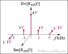
The graph shows the spectrum $R_{\rm TP}(f)$ of the received signal in the equivalent low-pass region, which is composed of Dirac delta lines
- at $f = 0$ (originating from the carrier),
- at $±2\ \rm kHz$ (originating from the cosine component) and
- at $±5\ \rm kHz$ (originating from the sine component).
The locus curve is the plot of the equivalent low-pass signal $r_{\rm TP}(t)$ in the complex plane, where $r_{\rm TP}(t)$ is the Fourier retransform of $R_{\ \rm TP}(f)$ .
Hints:
- This exercise belongs to the chapter Envelope Demodulation.
- Particular reference is made to the section Description using the equivalent low-pass signal.
Questions
Solution
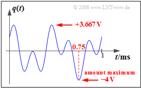
(1) The graph shows that the source signal can take on all values between $–4 \ \rm V$ and $+3.667\ \rm V$.
- For example, the maximum magnitude occurs at time $t = t_0 =0.75\ \rm ms$:
- $$q(t = t_0) = 2 \,{\rm V} \cdot \cos(2 \pi \cdot 2\,{\rm kHz} \cdot t_0 ) + 2 \,{\rm V} \cdot \sin(2 \pi \cdot 5\,{\rm kHz} \cdot t_0 )$$
- $$\Rightarrow \hspace{0.3cm}q(t = 0.75 \,{\rm ms}) = 2 \,{\rm V} \cdot \cos(3 \pi) + 2 \,{\rm V} \cdot \sin(7.5 \pi)= -4 \,{\rm V}\hspace{0.05cm}.$$
- From this, it follows for the maximum magnitude: $q_{\rm max}\hspace{0.15cm}\underline{ = 4 \ \rm V}$.
(2) In the graph on the information page, the weight of the Dirac delta line at $f = 0$ indicates the amplitude of the added carrier. This is $A_{\rm T}\hspace{0.15cm}\underline{ = 4\ \rm V }$.
- From this, we get the modulation depth $m = q_{\rm max}/A_{\rm T} \hspace{0.15cm}\underline{ = 1}$.
(3) Answers 2 and 3 are correct:
- Since the modulation depth is not greater than $m = 1$, the envelope demodulator does not cause distortion either.
- The main advantage of envelope demodulation is that no frequency and phase synchronization is necessary.
- A disadvantage is that a significantly higher power must be applied at the transmitter relative to synchronous demodulation.
- When $m = 1$, this results in three times the transmit power compared to DSB-AM without a carrier.
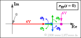
(4) Answers 1 and 3 are correct: When $ω_2 = 2 π · 2 \ \rm kHz$ and $ω_5 = 2 π · \ \rm 5 kHz$:
- $$ r_{\rm TP}(t) = 4 \,{\rm V} \hspace{-0.05cm}+\hspace{-0.05cm} 1 \,{\rm V} \cdot {\rm e}^{{\rm j} \cdot \hspace{0.03cm}\omega_{\rm 2}\cdot \hspace{0.03cm}t} \hspace{-0.05cm}+\hspace{-0.05cm} 1 \,{\rm V} \cdot {\rm e}^{-{\rm j} \cdot \hspace{0.03cm}\omega_{\rm 2}\cdot \hspace{0.03cm}t} \hspace{-0.05cm}-\hspace{-0.05cm} \hspace{0.15cm}{\rm j} \cdot1 \,{\rm V} \cdot {\rm e}^{{\rm j} \cdot \hspace{0.03cm}\omega_{\rm 5}\cdot \hspace{0.03cm}t} \hspace{-0.05cm}+\hspace{-0.05cm} {\rm j} \cdot1 \,{\rm V} \cdot {\rm e}^{-{\rm j} \cdot \hspace{0.03cm}\omega_{\rm 5}\cdot \hspace{0.03cm}t} \hspace{0.05cm}. \hspace{0.1cm}$$
Thus, in constructing the locus $r_{TP}(t)$, there are exactly five pointers to consider ⇒ answer 1 is correct. The graph shows a snapshot at time $t = 0$.
- The (red) carrier is given by the real pointer of length $4 \ \rm V$ for all time points. In contrast to the pointer diagram (showing the analytic signal), this does not rotate ⇒ Answer 2 is false.
- The third statement is similarly correct: The rotating pointers at negative frequencies rotate in mathematically negative direction ("clockwise") in contrast to the two pointers with $f > 0$.
- The last statement is false. The larger the frequency $f$, the faster the associated pointer rotates.
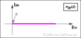
(5) Statements 1 and 2 are correct:
- In the example considered, the equivalent low-pass signal can be written as:
- $$r_{\rm TP}(t) = q(t) + A_{\rm T} \hspace{0.05cm}.$$
- Thus, it is obvious that $r_{\rm TP}(t)$ is always real.
- Moreover, it follows from subtasks (1) and (2) that $r_{\rm TP}(t) ≥ 0$.
This means:
- Here, the locus curve is a horizontal line on the real plane and always lies in the right half-plane.
- These are the two necessary conditions for an envelope demodulator to recover the signal without distortion.
- If one of these conditions is not satisfied, nonlinear distortions arise, not linear ones ⇒ Answer 3 is wrong.


