Difference between revisions of "Digital Signal Transmission/Intersymbol Interference for Multi-Level Transmission"
| (4 intermediate revisions by 2 users not shown) | |||
| Line 41: | Line 41: | ||
{{GraueBox|TEXT= | {{GraueBox|TEXT= | ||
$\text{Example 1:}$ Below you can see three eye diagrams (without noise) for the level numbers $M = 2$, $M = 3$ and $M = 4$. | $\text{Example 1:}$ Below you can see three eye diagrams (without noise) for the level numbers $M = 2$, $M = 3$ and $M = 4$. | ||
| − | [[File: | + | [[File:EN_Dig_T_3_4_S1b_neu.png|right|frame|Noiseless eye diagrams of a binary, ternary and quaternary system. Note: the normalized cutoff frequency $f_{\rm G} \cdot T = 0.6$ holds for all three diagrams|class=fit]] |
*The binary eye diagram is valid for a Gaussian low-pass with the cutoff frequency $f_{\rm G} \cdot T = 0.6$. With the "main value" $g_0 = 0.867 \cdot s_0$, the "postcursor" $g_{1} = 0.067 \cdot s_0$ and the "precursor" $g_{-1} = g_{1}$, the result in this case for the vertical eye opening (rounding to one decimal place) is: | *The binary eye diagram is valid for a Gaussian low-pass with the cutoff frequency $f_{\rm G} \cdot T = 0.6$. With the "main value" $g_0 = 0.867 \cdot s_0$, the "postcursor" $g_{1} = 0.067 \cdot s_0$ and the "precursor" $g_{-1} = g_{1}$, the result in this case for the vertical eye opening (rounding to one decimal place) is: | ||
| Line 61: | Line 61: | ||
| − | The graph shows the half eye opening $($normalized to $s_0)$ as a function of the quotient $f_{\rm G}/R_{\rm B}$ of the Gaussian receiver filter. In [[Aufgaben: | + | The graph shows the half eye opening $($normalized to $s_0)$ as a function of the quotient $f_{\rm G}/R_{\rm B}$ of the Gaussian receiver filter. In [[Aufgaben:Exercise_3.4Z:_Eye_Opening_and_Level_Number|Exercise 3.4Z]], this is calculated in analytical form as follows: |
:$$\ddot{o}_{\rm norm} = \frac{\ddot{o}(T_{\rm D})}{ 2 \cdot s_0} = \frac{M}{ M-1}\cdot \frac{g_0}{ | :$$\ddot{o}_{\rm norm} = \frac{\ddot{o}(T_{\rm D})}{ 2 \cdot s_0} = \frac{M}{ M-1}\cdot \frac{g_0}{ | ||
s_0} -1 = \frac{1}{ M-1}\cdot \big [1- 2 \cdot M \cdot {\rm Q} \left( | s_0} -1 = \frac{1}{ M-1}\cdot \big [1- 2 \cdot M \cdot {\rm Q} \left( | ||
| Line 150: | Line 150: | ||
| − | ⇒ Note: The degradations due to intersymbol interference in AMI and duobinary coding can also be displayed using the HTML5/JavaScript applet [[Applets: | + | ⇒ Note: The degradations due to intersymbol interference in AMI and duobinary coding can also be displayed using the HTML5/JavaScript applet [[Applets:Eye_Pattern_and_Worst-Case_Error_Probability|"Eye Diagram and Eye Opening"]]. However, the error probabilities apply only to the distortion-free channel $(a_\star = 0 \ \rm dB)$.<br> |
== Cutoff frequency optimization with pseudo-ternary coding == | == Cutoff frequency optimization with pseudo-ternary coding == | ||
| Line 164: | Line 164: | ||
{{BlaueBox|TEXT= | {{BlaueBox|TEXT= | ||
$\text{However, it has to be taken into account:}$ All results in this chapter are valid under the condition $H_{\rm K}(f=0) = 1$. | $\text{However, it has to be taken into account:}$ All results in this chapter are valid under the condition $H_{\rm K}(f=0) = 1$. | ||
| − | #If a redundancy-free signal or the duobinary- | + | #If a redundancy-free signal or the duobinary-encoded signal is to be transmitted over a DC-impermeable channel, a complex DC recovery is required, which is always associated with a degradation of the S/N ratio as well [TS87]<ref>Tröndle, K.; Söder, G.: Optimization of Digital Transmission Systems. Boston – London: Artech House, 1987, ISBN: 0-89006-225-0.</ref>.<br><br> |
# The AMI code is free of DC signals and can thus also be transmitted over a telephone channel ⇒ $H_{\rm K}(f=0) = 0$. This is the decisive reason why the AMI code is used in [[Examples_of_Communication_Systems/Allgemeine_Beschreibung_von_ISDN| ISDN]] ("Integrated Services Digital Network"), for example, despite otherwise poor properties.}}<br> | # The AMI code is free of DC signals and can thus also be transmitted over a telephone channel ⇒ $H_{\rm K}(f=0) = 0$. This is the decisive reason why the AMI code is used in [[Examples_of_Communication_Systems/Allgemeine_Beschreibung_von_ISDN| ISDN]] ("Integrated Services Digital Network"), for example, despite otherwise poor properties.}}<br> | ||
| Line 171: | Line 171: | ||
[[Aufgaben:Exercise_3.4:_Optimization_of_the_Cutoff_Frequency|Exercise 3.4: Optimization of the Cutoff Frequency]] | [[Aufgaben:Exercise_3.4:_Optimization_of_the_Cutoff_Frequency|Exercise 3.4: Optimization of the Cutoff Frequency]] | ||
| − | [[Aufgaben:Exercise_3.4Z: | + | [[Aufgaben:Exercise_3.4Z:_Eye_Opening_and_Level_Number|Exercise 3.4Z: Eye Opening and Level Number]] |
[[Aufgaben:Exercise_3.5:_Eye_Opening_with_Pseudoternary_Coding|Exercise 3.5: Eye Opening with Pseudoternary Coding]] | [[Aufgaben:Exercise_3.5:_Eye_Opening_with_Pseudoternary_Coding|Exercise 3.5: Eye Opening with Pseudoternary Coding]] | ||
Latest revision as of 15:14, 23 January 2023
Contents
Eye opening for redundancy-free multi-level systems
We further assume the following:
- NRZ rectangular transmission pulses,
- coaxial cable and AWGN noise,
- ideal channel equalization, and
- a Gaussian low-pass filter for noise power limitation.
In contrast to the last chapter, the still redundancy-free transmitted signal $s(t)$ is now no longer binary, but of $M$–level, which only has an effect in the set of of the amplitude coefficients:
- $$s(t) = \sum_{\nu = -\infty}^{+\infty} a_\nu \cdot g_s ( t - \nu \cdot T)\hspace{0.3cm}{\rm with}\hspace{0.3cm} a_\nu \in \{ a_1,\ \text{ ...} \ , a_\mu , \ \text{ ...} \ , a_{M}\}\hspace{0.05cm}.$$
Accordingly, the decision unit now has not only one, but $M-1$ decision thresholds and in the eye diagram $M-1$ eye openings are visible when the eye is open.
Comparing the eye diagrams (without noise) of a
- binary $(M = 2)$,
- ternary $(M = 3)$, and
- quaternary $(M = 4)$
transmission system with the same basic detection pulse $g_d(t)$ and the same symbol duration $T$, one obtains for the half vertical eye opening in general:
- $${\ddot{o}(T_{\rm D})}/{ 2} = \frac{g_0}{ M-1} - \sum_{\nu = 1}^{\infty} |g_{-\nu} | - \sum_{\nu = 1}^{\infty} |g_{\nu} |\hspace{0.05cm}.$$
⇒ $g_0 = g_d(t= 0)$ denotes the "main value" as in chapter "Consideration of Channel Distortion and Equalization". The two sums in the above equation take into account
- the "precursors" $g_1$, $g_2$, ... of the trailing pulses (second term), and
- the "trailers" or "postcursors" $g_{-1}$, $g_{-2}$, ... of the preceding pulses (last term).
Here, $g_\nu = g_d(t = \nu \cdot T)$ always holds.
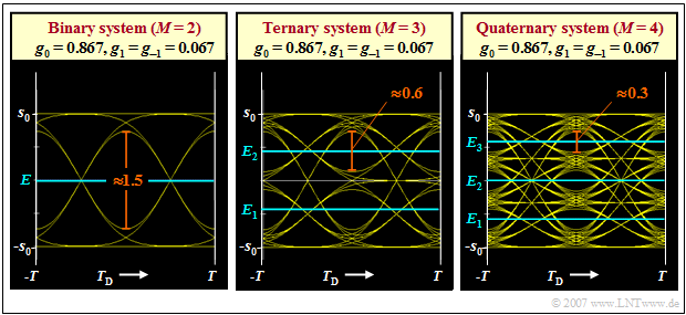
$\text{Example 1:}$ Below you can see three eye diagrams (without noise) for the level numbers $M = 2$, $M = 3$ and $M = 4$.
- The binary eye diagram is valid for a Gaussian low-pass with the cutoff frequency $f_{\rm G} \cdot T = 0.6$. With the "main value" $g_0 = 0.867 \cdot s_0$, the "postcursor" $g_{1} = 0.067 \cdot s_0$ and the "precursor" $g_{-1} = g_{1}$, the result in this case for the vertical eye opening (rounding to one decimal place) is:
- $${\ddot{o}(T_{\rm D})}= 2 \cdot (g_0 - 2 \cdot g_1) \approx 1.5 \cdot s_0 \hspace{0.05cm}.$$
- In the multi-level systems, the eye opening is per se smaller by a factor of $1/(M-1)$. Thus, the eye opening is reduced (relatively speaking) more by the ISI causing pulse values $g_1$ and $g_{-1}=g_1$ than in the binary system. One obtains with the same basic detection pulse values for
- $$M = 3\text{:} \hspace{0.2cm}{\ddot{o}(T_{\rm D})} = 2 \cdot (g_0/2 - 2 \cdot g_1) \approx 0.6 \cdot s_0 \hspace{0.05cm},$$
- $$M = 4\text{:} \hspace{0.2cm}{\ddot{o}(T_{\rm D})} = 2 \cdot (g_0/3 - 2 \cdot g_1) \approx 0.3 \cdot s_0 \hspace{0.05cm}.$$
- But when comparing the systems, it should be noted that the larger level number $M$ also increases the information flow. That is, the multi-level systems are better than these graphs indicate. More about this in the next section.
Comparison between binary and quaternary system
The comparison made in the last section is not fair because the information flow was not assumed to be the same.
- A system comparison at constant equivalent bit rate $R_{\rm B}$ must rather also take into account
- that in the (redundancy-free) multi-level systems the symbol duration $T$ is larger by a factor $\log_2 \ (M)$ than in the binary system, which has a favorable effect on the intersymbol interferences.
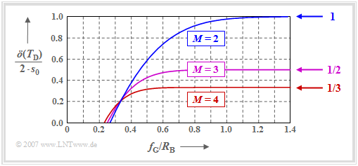
The graph shows the half eye opening $($normalized to $s_0)$ as a function of the quotient $f_{\rm G}/R_{\rm B}$ of the Gaussian receiver filter. In Exercise 3.4Z, this is calculated in analytical form as follows:
- $$\ddot{o}_{\rm norm} = \frac{\ddot{o}(T_{\rm D})}{ 2 \cdot s_0} = \frac{M}{ M-1}\cdot \frac{g_0}{ s_0} -1 = \frac{1}{ M-1}\cdot \big [1- 2 \cdot M \cdot {\rm Q} \left( \sqrt{2\pi} \cdot {\log_2}\hspace{0.1cm}(M) \cdot {f_{\rm G}}/{R_{\rm B}} \right)\big] \hspace{0.05cm}.$$
One can see from the graph:
- For broadband filter $($that is: for large $f_{\rm G})$ the binary system is clearly superior to the multi-level systems. The normalized half eye opening in the limiting case is $\ddot{o}_{\rm norm} = 1$ $(M = 2),$ $\ddot{o}_{\rm norm} = 1/2$ $(M = 3)$, $\ddot{o}_{\rm norm} = 1/3$ $(M = 4)$.
- As shown in the graph, for $f_{\rm G}/R_{\rm B} < 0.35$, the level number $M=4$ (red curve) leads to a larger eye opening than $M=2$ (blue curve). The ternary system $(M=3)$ lies almost in the entire range between binary and quaternary systems.
- It should also be mentioned that for the quaternary system, a closed eye results only with a cutoff frequency $f_{\rm G}/R_{\rm B} < 0.23$ $($which leads to very large error probabilities$)$, while a practically relevant binary transmission is already no longer possible for $f_{\rm G}/R_{\rm B} < 0.27$.
Comparison of the optimal cutoff frequencies
We now compare the optimal cutoff frequencies of the Gaussian filter, which result for $M=2$ and $M=4$, resp.
- The comparison is based on a coaxial transmission channel with the characteristic cable attenuation $a_\star$.
- The larger $a_\star$ (which also means: the longer the cable), the more the noise is amplified by the required equalization at the receiver.
Let's interpret the left graph first:
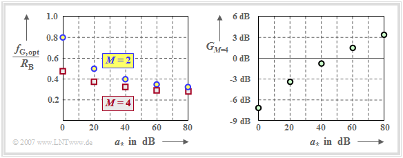
- With distortion-free channel $(a_\star = 0 \ \rm dB)$ the optimal (normalized) cutoff frequencies result to $f_\text{G, opt}/R_{\rm B} = 0.8$ $(M=2)$ and $f_\text{G, opt}/R_{\rm B} = 0.48$ $(M=4)$.
- According to the curve "half normalized eye opening" in the last section, the binary system is clearly superior to the quaternary system.
- With the characteristic cable attenuation $a_\star = 80 \ \rm dB$, the optimal cutoff frequency $f_\text{G, opt}/R_{\rm B} = 0.33$ is obtained for $M=2$.. For the quaternary system, a smaller value results again: $f_\text{G, opt}/R_{\rm B} = 0.28$.
However, the optimized binary system is not always better than the optimized quaternary system despite the larger eye opening, since the noise power must also be taken into account. This also becomes smaller with decreasing cutoff frequency.
The right graph shows the signal-to-noise ratio gain of the quaternary system over the binary system,
- $$G_{_{M=4}} = 10 \cdot {\rm lg}\hspace{0.1cm}\rho_{_{{\rm U},\hspace{0.05cm} M=4}} - 10 \cdot {\rm lg}\hspace{0.1cm}\rho_{_{{\rm U}, \hspace{0.05cm}M=2}},$$
when the cutoff frequencies are chosen optimally in each case according to the left graph. Accordingly:
- For $a_\star <50 \ \rm dB$, the binary system is optimal. For the distortion-free channel $(a_\star = 0 \ \rm dB)$, the SNR is about $7 \ \rm dB$ larger than with $M=4$.
- In contrast, more favorable ratios result for $a_\star >50 \ \rm dB$ with $M=4$. For $a_\star = 80 \ \rm dB$, the signal-to-noise ratio gain is greater than $3 \ \rm dB$ compared to $M=2$.
Eye opening for the pseudo-ternary codes
In the chapter "Symbolwise Coding", the pseudo-ternary codes were described in general and the eye diagrams with Nyquist pulse shaping were given for them.
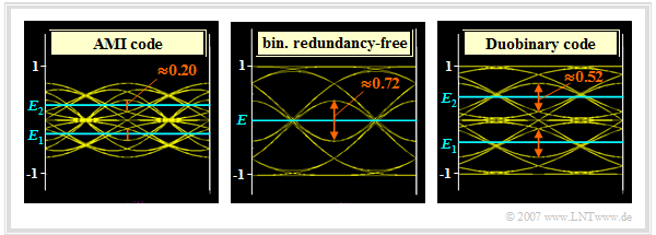
In the adjacent graphic you can see, in comparison to the redundancy-free binary code (center), the eye diagrams – in each case without noise – for
- the AMI code (on the left),
- the duobinary code (on the right).
The amplitude in each case is $s_0 = 1$. All eye diagrams are furthermore valid for a Gaussian receiver filter with cutoff frequency $f_\text{G} \cdot T = 0.4$, resulting in the following (normalized) basic detection pulse values:
- $$g_{0} \approx 0.68, \hspace{0.2cm} g_{1}= g_{-1} \approx 0.16, \hspace{0.2cm}\hspace{0.2cm} g_{2}= g_{-2}= \text{...} \approx 0 \hspace{0.05cm}.$$
Thus, for the redundancy-free binary system (middle graph), due to the intersymbol interference, we obtain for the eye opening
- $${\ddot{o}(T_{\rm D})}= 2 \cdot (g_0 - 2 \cdot g_1 ) = 0.72$$
- $$\Rightarrow \hspace{0.3cm} \ddot{o}_{\rm norm} = \frac{\ddot{o}(T_{\rm D})}{ 2 \cdot s_0} = 36\%$$
compared to $\ddot{o}(T_{\rm D}) = 2$ or $\ddot{o}_{\rm norm} = 100\%$ for the binary Nyquist system.
For the pseudo-ternary codes, there are two eye openings each and one needs two thresholds $E_1$ and $E_2$ for the ternary decision. Furthermore, since all pseudo-ternary codes operate at the same symbol rate as the redundancy-free binary system,
- the basic detection pulse values $g_\nu$ and also the noise rms value $\sigma_d$ are the same in both cases,
- the (half) eye opening is suitable for system optimization as well as the worst case SNR $\rho_{\rm U} = [\ddot{o}(T_{\rm D})/2]^2 /\sigma_d^2$ and the resulting worst–case error probability $p_{\rm U}$.
Let us now interpret the (left) eye diagram with AMI coding:
- The upper boundary of the upper eye belongs to the symbol sequence "$\text{...} -\hspace{-0.05cm}1,\hspace{0.05cm} {\it +\hspace{-0.05cm}1},\hspace{0.05cm} -\hspace{-0.05cm}\hspace{-0.05cm}1\hspace{0.05cm} \text{...}$" $($coefficient $a_{\nu = 0}$ italic$)$ and consequently lies at $d_{\rm top} = g_0 - 2\cdot g_1$.
- The lower boundary line $d_{\rm bottom} = g_1$ goes back to the symbol sequence "$\text{...} 0,\hspace{0.05cm} {\it 0},\hspace{0.05cm} +\hspace{-0.05cm}\hspace{-0.05cm}1 \text{...}$" and to the sequence "$\text{...} +\hspace{-0.05cm}\hspace{-0.05cm}1,\hspace{0.05cm} {\it 0},\hspace{0.05cm} 0\hspace{0.05cm} \text{...}$", respectively.
- Here it is considered that the sequence "$\text{...} +\hspace{-0.05cm}\hspace{-0.05cm}1,\hspace{0.05cm} {\it 0},\hspace{0.05cm} +\hspace{-0.05cm}\hspace{-0.05cm}1\hspace{0.05cm} \text{...}$" is excluded by the AMI coding rule. Thus, the eye opening of the AMI code is:
- $${\ddot{o}(T_{\rm D})}= d_{\rm top} - d_{\rm bottom} =g_0 - 3 \cdot g_1 = 0.20 \hspace{0.3cm}\Rightarrow \hspace{0.3cm} \ddot{o}_{\rm norm} = \frac{\ddot{o}(T_{\rm D})}{ 2 \cdot s_0} = 10\, \%.$$
- The upper decision threshold $E_2$ as well as the lower decision threshold $E_1$ are at
- $$E_2 = {1}/{2} \cdot (d_{\rm top} + d_{\rm bottom}) = {1}/{2} \cdot (g_0 - g_1) = 0.27 \hspace{0.05cm}, \hspace{0.2cm}E_1 = - 0.27 \hspace{0.05cm}.$$
In the duobinary code (right graph), the particularly unfavorable alternating symbol sequence does not occur and one obtains for the eye opening as well as the decision thresholds:
- $$d_{\rm top}= g_0, \hspace{0.2cm} d_{\rm bottom} = g_1 \hspace{0.3cm}\Rightarrow \hspace{0.3cm}{\ddot{o}(T_{\rm D})} = g_0 - g_1 = 0.52 \hspace{0.3cm}\Rightarrow \hspace{0.3cm} \ddot{o}_{\rm norm} = 26\, \% \hspace{0.05cm}, \hspace{0.3cm} E_2 = {1}/{2} \cdot (g_0 + g_1) = 0.42 \hspace{0.05cm}, \hspace{0.2cm}E_1 = - 0.42 \hspace{0.05cm}.$$
⇒ Note: The degradations due to intersymbol interference in AMI and duobinary coding can also be displayed using the HTML5/JavaScript applet "Eye Diagram and Eye Opening". However, the error probabilities apply only to the distortion-free channel $(a_\star = 0 \ \rm dB)$.
Cutoff frequency optimization with pseudo-ternary coding
Considering a coaxial transmission channel and the thus necessary channel equalization, the following statements are possible:
- The AMI code always leads to a worse signal-to-noise ratio than the redundancy-free binary code if the overall frequency response is Gaussian. With the characteristic cable attenuation $a_\star = 80 \ \rm dB$, the signal-to-noise ratio loss is about $11 \ \rm dB$.
- This loss is due to the fact that, despite ternary coding, the symbol rate is not reduced compared to the binary reference system. This has the consequence that with the AMI code already a cutoff frequency $f_\text{G} \cdot T < 0.36$ leads to a closed eye.
- In contrast, with the duobinary code a closed eye results only from $f_\text{G} \cdot T < 0.22$. As a result, the optimal cutoff frequency is also smaller than with the binary system. At 80 dB cable attenuation, the duobinary code in combination with $f_\text{G} \cdot T =0.28$ is $3.3 \ \rm dB$ better than the best value with redundancy-free binary coding.
$\text{However, it has to be taken into account:}$ All results in this chapter are valid under the condition $H_{\rm K}(f=0) = 1$.
- If a redundancy-free signal or the duobinary-encoded signal is to be transmitted over a DC-impermeable channel, a complex DC recovery is required, which is always associated with a degradation of the S/N ratio as well [TS87][1].
- The AMI code is free of DC signals and can thus also be transmitted over a telephone channel ⇒ $H_{\rm K}(f=0) = 0$. This is the decisive reason why the AMI code is used in ISDN ("Integrated Services Digital Network"), for example, despite otherwise poor properties.
Exercises for the chapter
Exercise 3.4: Optimization of the Cutoff Frequency
Exercise 3.4Z: Eye Opening and Level Number
Exercise 3.5: Eye Opening with Pseudoternary Coding
References
- ↑ Tröndle, K.; Söder, G.: Optimization of Digital Transmission Systems. Boston – London: Artech House, 1987, ISBN: 0-89006-225-0.


