Difference between revisions of "Aufgaben:Exercise 2.4: Distortion Factor and Distortion Power"
m (Guenter moved page Aufgabe 2.4: Klirrfaktor und Verzerrungsleistung to Exercise 2.4: Distortion Factor and Distortion Power) |
|||
| Line 172: | Line 172: | ||
| − | [[Category:Linear and Time-Invariant Systems: Exercises|^2.2 | + | [[Category:Linear and Time-Invariant Systems: Exercises|^2.2 Nonlinear Distortions^]] |
Revision as of 11:10, 20 September 2021
A cosine signal
- $$x_1(t) = A_x \cdot \cos(\omega_0 t)$$
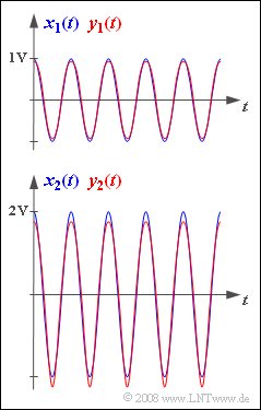
with the amplitude $A_x = 1 \ \rm V$ is applied to the input of a message transmission system to test it. Then, the following signal occurs at the system output:
- $$y_1(t) = {0.992 \,\rm V} \cdot \cos(\omega_0 t) - {0.062 \,\rm V} \cdot \cos(2\omega_0 t)+ \hspace{0.05cm}\text{...}$$
In the upper graph the signals $x_1(t)$ and $y_1(t)$ are shown. Harmonics with amplitudes smaller than $10 \ \rm mV$ are not considered here.
The bottom image shows the input signal $x_2(t)$ with the ampiltude $A_x = 2 \ \rm V$ and the corresponding output signal, again without harmonics smaller than $10 \ \rm mV$:
- $$y_2(t) \hspace{-0.05cm}=\hspace{-0.05cm}{1.938 \,\rm V} \cdot \cos(\omega_0 t)\hspace{-0.05cm} -\hspace{-0.05cm} {0.234 \,\rm V} \cdot \cos(2\omega_0 t) \hspace{-0.05cm}+\hspace{-0.05cm} {0.058 \,\rm V} \cdot \cos(3\omega_0 t)\hspace{-0.05cm} -\hspace{-0.05cm}{0.018 \,\rm V} \cdot \cos(4\omega_0 t) \hspace{-0.05cm}+\hspace{-0.05cm} \hspace{0.05cm}\text{...}$$
It is obvious that the indices "1" and "2" respectively denote the normalised amplitude of the input signal.
The system is supposed to be analysed based on the signal–to–distortion–power ratio
- $$\rho_{\rm V} = { P_{x}}/{P_{\rm V}} \hspace{0.3cm} \Rightarrow \hspace{0.3cm} 10 \cdot \lg \hspace{0.1cm}\rho_{\rm V} = 10 \cdot \lg \hspace{0.1cm}{ P_{x}}/{P_{\rm V}}\hspace{0.3cm} \left( {\rm in \hspace{0.15cm} dB} \right)$$
defined in the section Quantitative measure for the signal distortions and the distortion factor $K$ :
- $P_x$ denotes the power of the input signal.
- The distortion power $P_{\rm V}$ respectively represents the power (the root mean square) of the difference signal $\varepsilon(t) = y(t) - x(t)$ .
To determine the powers $P_{x}$ and $P_{\rm V}$ it is necessary to take the average of the squared signals in each case. However, it is easier to calculate the powers in the frequency domain in this task.
Please note:
- The task belongs to the chapter Nonlinear Distortion.
- All powers required here refer to the resistance $R = 1 \ \rm \Omega$ and thus have the unit ${\rm V}^2$.
Questions
Solution
- $$K \approx K_2 = \frac{0.062 \,\,{\rm V}}{0.992 \,\,{\rm V}} \hspace{0.15cm}\underline{\approx 6.25 \%}.$$
(2) For the input amplitude $A_x = 2 \ \rm V$ (bottom sketch) the various distortion factors are:
- $$K_2 = \frac{0.234 \,\,{\rm V}}{1.938 \,\,{\rm V}} \approx 0.121, \hspace{0.5cm} K_3 = \frac{0.058 \,\,{\rm V}}{1.938 \,\,{\rm V}} \approx 0.030, \hspace{0.5cm}K_4 = \frac{0.018 \,\,{\rm V}}{1.938 \,\,{\rm V}} \approx 0.009.$$
- Thus, the overall distortion factor is:
- $$K = \sqrt{K_2^2 + K_3^2 + K_4^2 +\text{ ...} }\hspace{0.15cm}\underline{ \approx 12.5 \%}.$$
(3) The first two proposed solutions are correct:
- Here, the nonlinear distortions cause the lower half-wave to be more peaked than the upper half-wave.
- In addition, $y_{\rm max} = 1.75 \ \rm V$ and $y_{\rm min} = -2.25 \ \rm V$ hold since $y(t)$ does not contain any direct (DC) signals. Hence, there is no symmetry with respect to the zero line anymore.
- For a nonlinear system, the distortion factor $K$ is independent of the frequency of the cosine input signal but strongly dependent on its amplitude.
(4) The root mean square (rms) value of a cosine signal is known to be $\sqrt{0.5}$–times the amplitude. The square of this is the "power":
- $$P_x = \frac{A_x^2}{2} = \frac{(2 \,{\rm V})^2}{2}\hspace{0.15cm}\underline{ = 2\,{\rm V^2}}.$$
- Actually, the power also depends on the reference resistance $R$ and has the unit "watt".
- $P_x = 2 \ \rm W$ is obtained with $R = 1 \ \rm \Omega$ , so exactly the same numerical value as in this simpler calculation.
(5) Denoting
- the amplitude of the fundamental wave of $y_2(t)$ by $A_1$ and
- the so-called harmonics by $A_2$, $A_3$ and $A_4$ ,
the distortion power is thus by computing it in the frequency domain:
- $$P_{\rm V} = \frac{1}{2} \cdot \big[ (A_1 - A_x)^2 + A_2^2+ A_3^2+ A_4^2\big] = \frac{1}{2} \cdot \big[ (-2 \,{\rm V} \hspace{-0.05cm}+ \hspace{-0.05cm}1.938 \,{\rm V} )^2 \hspace{-0.05cm}+ \hspace{-0.05cm} (0.234 \,{\rm V})^2 \hspace{-0.05cm}+ \hspace{-0.05cm} (0.058 \,{\rm V})^2 \hspace{-0.05cm}+ \hspace{-0.05cm} (0.018 \,{\rm V})^2 \big] \hspace{0.15cm}\underline{\approx 0.031 \,{\rm V}^2}.$$
Here, $A_x$ denotes the amplitude of the input signal. The signs of the harmonics do not matter in this calculation.
(6) Using the results of subtasks (4) and (5) the following is obtained:
- $$10 \cdot \lg \rho_{V} = 10 \cdot \lg \frac{P_x}{P_{\rm V}}= 10 \cdot \lg \frac{2.000\,{\rm V^2}}{0.031 \,{\rm V}^2} \hspace{0.15cm}\underline{\approx 18.10 \,{\rm dB}}.$$
(7) Proposed solutions 1 and 3 are correct:
- The first statement is correct because it holds that
- $$K^2 = \frac{A_2^2 + A_3^2 + A_4^2 + ... }{A_1^2}.$$
- In contrast, the following holds for the reciprocal of the signal–to–distortion–power ratio:
- $${1}/{\rho_{\rm V}} = \frac{(A_1 - A_x)^2+A_2^2 + A_3^2 + A_4^2 + \text{...} }{A_x^2}.$$
- When calculating the distortion power $P_{\rm V}$ a falsification of the amplitude of the fundamental wave $($this is now $A_1$ instead of $A_x)$ is also taken into account. Moreover, the distortion power is not in terms of $A_1^2$ but in terms of $A_x^2$ .
- Generally, the following relationship holds between the signal–to–distortion–power ratio and the distortion factor:
- $${\rho_{\rm V}} = \frac{A_x^2}{(A_1 - A_x)^2 + K^2 \cdot A_1^2}.$$
- With $A_1 = A_x$ this equation is simplified as follows:
- $${\rho_{\rm V}} = {1}/{ K^2 }.$$
Remarks:
- A distortion factor of $1\%$ in this case corresponds to the result $10 \cdot \lg \rho_{\rm V} = 40 \,{\rm dB}$.
- Using the distortion factor $K = 0.125$ from subtask (2) $10 \cdot \lg \rho_{\rm V} = 18.06 \,{\rm dB}$ would have been obtained immediately with the approximation $A_1 \approx A_x$ .
- The actual value $(18.10 \ \rm dB)$ calculated in subtask (7) differs from this only insignificantly.
