Difference between revisions of "Aufgaben:Exercise 3.11: Viterbi Receiver and Trellis Diagram"
| Line 21: | Line 21: | ||
*The exercise belongs to the chapter [[Digital_Signal_Transmission/Viterbi_Receiver|"Viterbi Receiver"]]. | *The exercise belongs to the chapter [[Digital_Signal_Transmission/Viterbi_Receiver|"Viterbi Receiver"]]. | ||
| − | *Reference is also made to the section [[Digital_Signal_Transmission/Optimal_Receiver_Strategies# | + | *Reference is also made to the section [[Digital_Signal_Transmission/Optimal_Receiver_Strategies#Maximum-a-posteriori_and_maximum.E2.80.93likelihood_decision_rule|"Maximum-a-posteriori and Maximum–Likelihood decision rule"]]. |
* All quantities here are to be understood normalized. Also assume unipolar and equal probability amplitude coefficients: | * All quantities here are to be understood normalized. Also assume unipolar and equal probability amplitude coefficients: | ||
Revision as of 13:16, 4 July 2022
The Viterbi receiver allows a low-effort realization of the maximum likelihood decision rule. It contains the system components listed below:
- A matched filter adapted to the basic transmission pulse with frequency response $H_{\rm MF}(f)$ and output signal $m(t)$,
- a sampler spaced at the symbol duration $T$, which converts the continuous-time signal $m(t)$ into the discrete-time sequence $〈m_{\rm \nu}〉$,
- a decorrelation filter with frequency response $H_{\rm DF}(f)$ for removing statistical ties between noise components of the sequence $〈d_{\rm \nu}〉$,
- the Viterbi decision, which uses a trellis-based algorithm to obtain the sink symbol sequence $〈v_{\rm \nu}〉$.
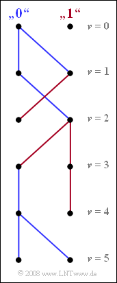
The graph shows the simplified trellis diagram of the two states "$0$" and "$1$" for time points $\nu ≤ 5$. This diagram is obtained as a result of evaluating the two minimum accumulated metrics ${\it \Gamma}_{\rm \nu}(0)$ and ${\it \Gamma}_{\rm \nu}(1)$ corresponding to Exercise 3.11Z.
Notes:
- The exercise belongs to the chapter "Viterbi Receiver".
- Reference is also made to the section "Maximum-a-posteriori and Maximum–Likelihood decision rule".
- All quantities here are to be understood normalized. Also assume unipolar and equal probability amplitude coefficients:
- $${\rm Pr} (a_\nu = 0) = {\rm Pr} (a_\nu = 1)= 0.5.$$
- The topic is also covered with the interactive SWF applet "Properties of the Viterbi Receiver".
Questions
Solution
- The signal $m(t)$ after the matched filter $H_{\rm MF}(f)$ has the largest possible signal-to-interference power ratio.
- However, the noise components of the sequence $〈m_{\rm \nu}〉$ are (strongly) correlated due to the spectral shaping.
- The task of the discrete-time decorrelation filter with the frequency response $H_{\rm DF}(f)$ is to dissolve these bonds, which is why the name "whitening filter" is also used for $H_{\rm DF}(f)$.
- However, this is possible only at the cost of increased noise power ⇒ consequently, the last proposed solution does not apply.
(2) The two arrows arriving at $\underline {\nu = 1}$ are each drawn in blue and indicate the symbol $a_1 = 0$. Thus, the initial symbol $a_1$ is already fixed at this point. Similarly, the symbols $a_3 = 1$ and $a_5 = 0$ are already fixed at the timesn $\underline {\nu = 3}$ and $\underline {\nu = 5}$, respectively.
In contrast, at time $\nu = 2$, a decision regarding symbol $a_2$ is not possible.
- Under the hypothesis that the following symbol $a_3 = 0$ would result in symbol $a_2 = 1$ (at "$0$" a red path arrives, thus coming from "$1$").
- In contrast, the hypothesis $a_3 = 1$ leads to the result $a_2 = 0$ (the path arriving at "$1$" is blue).
The situation is similar at time $\nu = 4$.
(3) From the continuous paths at $\nu = 5$ it can be seen:
- $$a_{1}\hspace{0.15cm}\underline {=0} \hspace{0.05cm},\hspace{0.2cm} a_{2}\hspace{0.15cm}\underline { =0} \hspace{0.05cm},\hspace{0.2cm}a_{3}\hspace{0.15cm}\underline {=1} \hspace{0.05cm},\hspace{0.2cm} a_{4}\hspace{0.15cm}\underline {=0} \hspace{0.05cm},\hspace{0.2cm} a_{5}\hspace{0.15cm}\underline {=0} \hspace{0.05cm}.$$
(4) Only the second statement is correct:
- Since the source symbols "$0$" and "$1$" were assumed to be equally probable, the ML receiver (Viterbi) is identical to the MAP receiver.
- A threshold decision (which makes a symbol-by-symbol decision at each clock) has the same error probability as the Viterbi receiver only if there is no intersymbol interference.
- This is obviously not the case here, otherwise it should be possible to make a final decision at every time $\nu$.
- The first statement is also not true. Indeed, this would mean that the Viterbi receiver can have error probability $0$ in the presence of statistical noise. This is not possible for information-theoretic reasons.
