Difference between revisions of "Examples of Communication Systems/UMTS Network Architecture"
| Line 334: | Line 334: | ||
| − | ==IP | + | ==IP core networks == |
<br> | <br> | ||
| − | UMTS Release 5 introduced, among other things, ''' | + | UMTS Release 5 introduced, among other things, '''»IP Core Networks«'''. |
| + | |||
| + | #In this case, both the user data and the control data are transmitted over an internal IP network. | ||
| + | #This means that both circuit-switched services and packet-switched services are provided on the basis of IP protocols. | ||
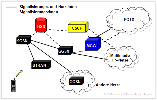
[[File:P_ID1525__Bei_T_4_2_S9_v1.png|right|frame|Network architecture of UMTS – Release 5]] | [[File:P_ID1525__Bei_T_4_2_S9_v1.png|right|frame|Network architecture of UMTS – Release 5]] | ||
| − | |||
| − | |||
| + | The graph shows this network architecture in schematic form. Compared with the original UMTS network architecture $($Release 99$)$, the following nodes have been added to the network: | ||
| + | *The '''»Media Gateway«''' $\rm (MGW)$ is responsible for recovering voice packets converted to "'voice-over-IP" $\rm (VoIP)$ into conventional voice data. | ||
| − | + | *The '''»Home Subscriber Server«''' $\rm (HSS)$ combines the registers "HLR" and "VLR" known from UMTS Release 99. | |
| − | *The ' | ||
| − | |||
| − | |||
| + | *The '''»Call State Control Function«''' $\rm (CSCF)$ node is responsible for the overall control of the IP network in UMTS Release 5 and establishes the communication between CSCF node and subscriber via the "session initiation protocol" $\rm (SIP)$. | ||
| − | |||
Major '''advantages''' of IP networks are: | Major '''advantages''' of IP networks are: | ||
| − | + | #A forward-looking alternative to the previou design, | |
| − | + | #a low-cost routing technology ⇒ large savings in switching equipment, | |
| − | + | #great flexibility in the introduction of new services, and | |
| − | + | #an ease of implementation of network monitoring techniques. | |
| − | However, crucial '''disadvantages''' of this architecture at | + | However, crucial '''disadvantages''' of this architecture $($ at 2011$)$ include: |
| − | + | #The cumbersome integration of second generation cellular infrastructure, | |
| − | + | #the need for transition nodes to convert the data in so-called gateways, and | |
| − | + | #the lack of a clear and reliable security concept. | |
Revision as of 18:09, 2 February 2023
Contents
- 1 Basic units of the system architecture
- 2 Domains and interfaces
- 3 Access level architecture
- 4 Physical channels
- 5 Logical channels
- 6 Transport channels
- 7 Communication within the ISO/OSI layer model
- 8 Cellular architecture of UMTS
- 9 What is cell breathing?
- 10 Handover in UMTS
- 11 IP core networks
- 12 Exercises for the chapter
Basic units of the system architecture
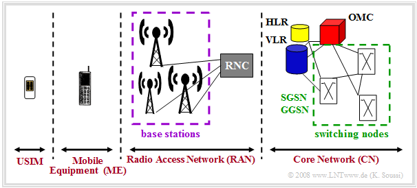
In the architecture of UMTS networks, a distinction is made between four basic logical units. The interaction of these units enables the operation of the entire network.
In the graphic you can see:
- $\rm Universal \ Subscriber \ Identity \ Module \ (USIM)$
The USIM is a removable chip card that contains radio information and information for unique identification and authentication of the subscriber. It differs from the conventional SIM card in that it has enhanced security features, larger memory capacity, and an integrated microprocessor that is used to run programs.
- $\rm Mobile \ Equipment \ (ME)$ – Equipped with a USIM card, the UMTS terminal provides both the radio interface for data transmission and the user controls. It differs from the common GSM mobile station in that it offers enhanced functionality, multimedia applications, and more complex and diverse services. Often, the designations "User Equipment" $\rm (UE)$ and "Terminal Equipment" $\rm (TE)$ can also be found.
- $\rm Radio \ Access \ Network \ (RAN)$ – This refers to the fixed network infrastructure of UMTS, which is responsible for radio transmission and related tasks. The RAN contains the base stations and the control nodes that connect the RAN and the "Core Network".
- $\rm Core \ Network \ (CN)$ – This represents the wide area network and is responsible for data transport. It contains switching facilities $\rm (SGSN, GGSN)$ to external networks and databases for mobility and subscriber management s $\rm (HLR,\ VLR)$. The core network also contains the "operation and maintenance center" $\rm (OMC)$ required to manage the overall network.
Domains and interfaces
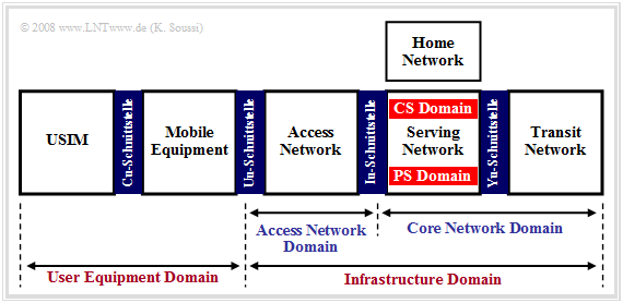
The units of the UMTS network listed on the last page are grouped into so-called »domains«. This refers to functional blocks that serve to standardize and study the functional units and interfaces within the UMTS network.
Two main categories of domains are distinguished, viz.
- the "User Equipment Domain", and
- the "Infrastructure Domain".
⇒ The »User Equipment Domain« contains all functions that enable access to the UMTS network, such as encryption functions for the transmission of data via the radio interface. One can divide this domain into two domains:
- the "USIM Domain" – the SIM card is a part of this domain;
- the "Mobile Equipment Domain" – it contains all the functions that a terminal device has.
These two domains are connected via the "Cu interface" which includes the electrical and physical specifications as well as the protocol stack between the USIM card and the terminal device. This allows USIM cards from different network operators to operate with all terminal devices.
Another important interface is the "Uu interface", which establishes the radio link between the mobile station and the infrastructure domain .
⇒ The »Infrastructure Domain« is divided into the following two domains:
- The "Access Network Domain" groups all base stations – in UMTS called "Node B" – and the functions of the "Radio Access Network" $\rm (RAN)$.
- The "Core Network Domain" is responsible for the most error-free transmission and transport of user data.
These two domains are connected via an "Iu interface". This interface is responsible for data switching between the access and the core network and is the separation between transport layer and radio network layer.
The "Core Network Domain" can in turn be divided into three sub-domains:
- The "Serving Network" contains all functions and information necessary to access the UMTS network.
- The "Home Network" contains all functionalities that are performed in the home network of a $($foreign$)$ subscriber.
- The "Transit Network" – this only takes effect if database queries are to be performed in the subscriber's home network and the "Serving Network" is not directly connected to the "Home Network".
Access level architecture
UMTS networks support both "circuit-switching" and "packet-switching".
$\text{Distinctive features:}$
- In »Circuit Switching« $\rm (CS)$, the radio channel is assigned to the two communication partners for the entire duration of the connection until all information has been transmitted. Only then the channel is released.
- In »Packet Switching« $\rm (PS)$, the participants cannot use the channel exclusively, but the data stream is divided in the transmitter into small data packets – each with the destination address in the header – and only then sent. The channel is shared by several participants
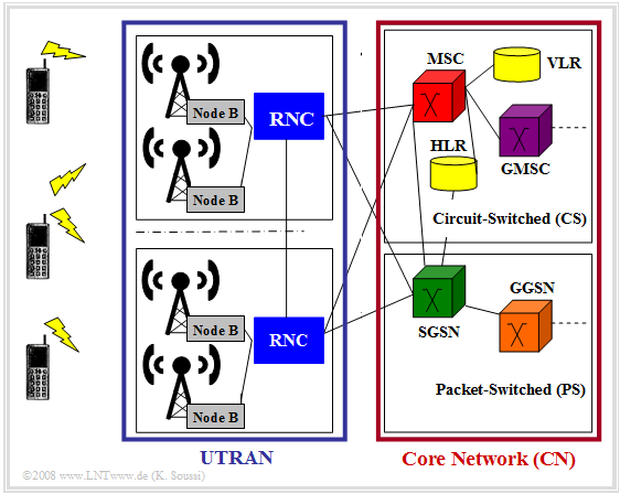
The two modes can also be recognized in the access level of the UMTS network in the core network $\rm (CN)$, which is shown in the graph.
The access layer can be divided into two main blocks:
⇒ The »UMTS Terrestrial Radio Access Network« $\rm (UTRAN)$ ensures radio transmission of data between the transport layer and the radio network layer.
The UTRAN includes the base stations and the control nodes, whose functions are mentioned below:
- A "Node B" – as a UMTS base station is usually called – includes the antenna equipment as well as the CDMA receiver and is directly connected to the radio interfaces of the mobile equipment. Its tasks include data rate adaptation, data and channel encoding or decoding, interleaving, and modulation or demodulation. Each base station can power one or more cells.
- The "Radio Network Controller" $\rm (RNC)$base station is responsible for controlling the base stations. Likewise, within the cells, it is responsible for call acceptance control, encryption and decryption, ATM switching, channel assignment, handover and power control.
⇒ The »Core Network« $\rm (UTRAN)$ is responsible for switching the data within the UMTS network $($both, circuit-switched and packet-switched$)$ .
For this purpose, it contains at circuit-switched transmission the following hardware and software components:
- The "Mobile Services Switching Center" $\rm (MSC)$ is responsible for call routing, localization, authentication, handover and data encryption.
- The "Home Location Register" $\rm (HLR)$ contains all subscriber data; tariff model, telephone number, authorizations and keys, ...
- The "Visitor Location Register" $\rm (VLR)$ contains information about locally registered users and copies of records from its HLR. This data is dynamic.
In circuit-switched transmission there are the following facilities or registers:
- The "Serving GPRS Support Node" $\rm (SGSN)$ is responsible for routing and authentication instead of MSC and VLR and keeps a local copy of the user information.
- The "Gateway GPRS Support Node" $\rm (GGSN)$ there are transitions to other packet data networks such as the Internet.
Incoming packets are filtered by an integrated firewall and forwarded to the appropriate SGSN. - The "GPRS Register" $\rm (GR)$ is part of the HLR and contains additional information needed for packet-switched transmission.
Physical channels
Physical channels are used for communication on the physical level of the radio interface and are processed within a base station $($"Node B"$)$. A distinction is made between "dedicated physical channels" and "shared physical channels".
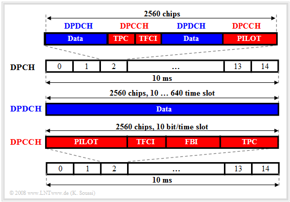
The »dedicated physical channels« are permanently assigned to individual communication partners. These include:
- Dedicated Physical Data Channel $($DPDCH$)$ – This is a unidirectional uplink channel that transports payload and signaling data from higher layers.
- Dedicated Physical Control Channel $($DPCCH$)$ – This control channel contains physical layer information for transmission control, line control commands, and transport format indicators, ...
- Dedicated Physical Channel $($DPCH$)$ – This channel includes the DPDCH and the DPCCH in the downlink and has a length of $2560$ chips.
The diagram shows the structural design of the DPDCH (blue), of the DPCCH (red) as well as the enveloping DPCH (black).
- In the DPCH, $15 \cdot 2560 = 38400$ chips are transmitted in $10 \ \rm ms$, resulting in the chip rate $3.84 \ \rm Mchip/s$.
- The user data in the DPDCH is split and per time slot are transmitted $($depending on the spreading factor $J)$ between $10$ bits $($if $J = 256)$ and $640$ bits $($if $J = 4)$.
- In the DPCCH, ten control bits are transmitted uniformly per time slot.
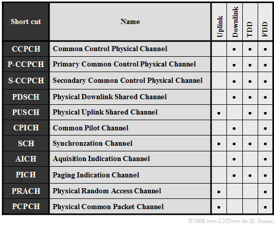
The table lists the »shared physical channels« by all participants. The following describes the characteristics of some selected channels:
- The CCPCH is a downlink channel with two subchannels: The "P-CCPCH" contains data necessary for operation within a radio cell, while the "S-CCPCH" contains data responsible for the paging procedure and for the transport of control data.
- The PDSCH and the PUSCH are shared channels that can transport both payload and control data. The first is solely responsible for the downlink, the second for the uplink.
- The PRACH controls the message transmission of the random access channel RACH, while the PCPCH is responsible for transporting data packets using the CDMA/CDM method.
The following channels are responsible for the control and synchronization of the overall system:
- The CPICH determines the affiliation of the mobile to a base station.
- The SCH is used for cell search and synchronization of the mobile station.
- The AICH checks and determines the availability of the system.
- The PICH is responsible for paging during subscriber localization.
Logical channels
The logical channels are located in the $\rm MAC$ $($"Medium Access Control"$)$ reference layer and are identified by the type of the transmitted data.
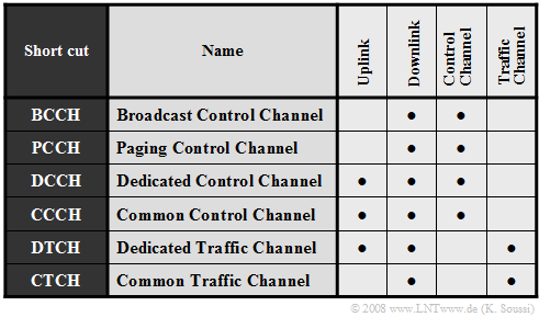
The logical channels compiled in the table can be divided into two classes, namely.
- »Control Channels« $($ending with "CCH"$)$:
- Control information $($"BCCH"$)$ as well as paging information $($"PCCH"$)$ are transported via the control channels.
- Subscriber-specific signaling data $($"DCCH"$)$ or transport information can also be exchanged between subscriber devices and the UTRAN $($"CCCH"$)$ over this.
- »Traffic Channels« $($ending with "TCH"$)$:
- Subscriber information is exchanged over the traffic channels.
- While the "DTCH" can be assigned individually to a mobile subscriber for user data transport, a "CTCH"  is predominantly assigned to all or to a predefined subscriber group.
Transport channels
Transport channels are located in the physical layer of the "ISO/OSI layer model". They
- are characterized by the parameters of the data transmission $($e.g. the data rate$)$,
- ensure the desired requirements regarding error protection mechanisms, and
- determine the type of data transmission – the "how", so to speak.
Two classes of transport channels are distinguished, namely "dedicated transport channels" and "shared transport channels".
The class of »dedicated transport channels« $\rm (DTCH)$:
- This class includes the "dedicated channels" $($"DCH"$)$, which are permanently assigned to participants.
- DCH transports both user data and control data $($handover data, measurement data, ...$)$ to the higher layers, where they are then interpreted and processed.
The »common transport channels« $\rm (CTCH)$ include, for example:
- The "Broadcast Channel" $($"BCH"$)$ is a downlink channel that distributes network operator-specific radio cell data to the subscribers. It is characterized by its relatively high power and low data rate $($only $\text{3.4 kbit/s)}$, in order to provide all users with the most error-free reception and high process gain.
- The "Forward Access Channel" $($"FACH"$)$ is a downlink channel, responsible for transporting control data.
A cell may contain several FACH channels, one of which must have a low data rate to allow all users to evaluate its data. - The "Random Access Channel" $($"RACH"$)$ is a unidirectional uplink channel. The subscriber can use it to express the desire to establish a radio link.
It can also be used to transmit small amounts of data. - The "Common Packet Channel" $($"CPCH"$)$ is a unidirectional uplink data channel for packet-oriented services and an extension of the RACH channel.
- The "Paging Channel" $($"PCH"$)$ is a unidirectional downlink channel for locating a subscriber with data for the paging procedure.
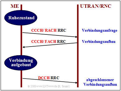
$\text{Example 1:}$ This diagram is intended to explain the interaction between the transport channels "RACH" and "FACH" with the logical channels "CCCH" and "DCCH" in a simple call setup.
Some explanations of this diagram:
- A mobile equipment $\rm (ME)$ expresses a request for a connection setup.
- First, using the logical channel CCCH and the transport channel RACH a connection request is then sent via the UTRAN to the radio network controller $\rm (RNC)$.
- For this purpose, the RRC protocol $($"Radio Resource Control"$)$ is used, which has the task of providing signaling between the subscriber and UTRAN/RNC.
- The "Radio Network Controller" $\rm (RNC)$ responds to this request via the transport channel FACH. Thereby the necessary control data for the connection setup is sent to the subscriber.
- Only then the connection is actually established using the logical channel DCCH
.
Communication within the ISO/OSI layer model
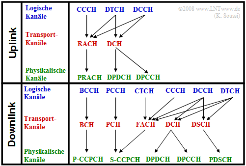
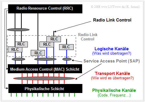
Communication between the different layers of the ISO/OSI model is ensured by the logical, physical and transport channels presented on the last pages.
The graph on the right shows the structure for both, the uplink and downlink directions.
To guarantee functionality and data exchange within the overall model, these must be mapped to each other according to the graph:
- First, the logical channel is mapped to the transport channel,
- then the mapping of the transport channel to the physical channel.
The lower (left) graphic is intended to give an overall view of the structure of the three lowest layers of the ISO/OSI model and to convey the interactions of the different channel types.
Cellular architecture of UMTS
To enable a nationwide network with low transmission power and sufficient frequency economy, radio cells are also set up in UMTS, as in GSM.
- The radio cells in the UMTS network $($carrier frequency $\text{2 GHz)}$ are significantly smaller than in GSM $($carrier frequency $\text{900 MHz)}$,
- since the range of radio signals decreases with increasing frequency for the same transmission power.
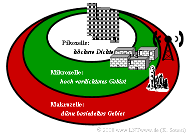
The graph shows the cell structure of UMTS. One recognizes from it a hierarchical structure and three types of radio cells:
- »Macrocells« are the largest cells with a diameter of four to six kilometers.
- They allow relatively fast movements.
- For example, a movement speed up to $500\ \rm km/h$ is allowed if the data rate is $144 \ \rm kbit/s$.
- A macrocell can potentially overlay a large number of microcells and picocells.
- »Microcells« are much smaller than macrocells at one to two kilometers in diameter.
- They allow higher data rates up to $384 \rm kbit/s$, but only slower movement speeds.
- For example, at the maximum data rate, the maximum allowed speed is only $120\ \rm km/h$.
- A microcell overlays none, one, or a plurality of picocells.
- »Picocells« serve only very small areas about $100$ meters in diameter, but very high data volumes.
- They are used in high density locations such as airports,# stadiums,# ...
- Data rates up to $2\ \rm Mbit/s$ are theoretically allowed.
Since UMTS uses as multiple access method "Code Division Multiple Access" $\rm (CDMA)$, all subscribers use the same frequency channel.
- This results in a relatively high interference power and a very low carrier-to-interference ratio $\rm (CIR)$.
- This is at least significantly smaller than for "GSM", which is based on FDMA and TDMA.
- A low CIR can significantly impair transmission quality, namely when signals from different subscribers destructively overlap, resulting in information loss.
$\text{There are two types of interference:}$
- »Intracell interference« occurs when multiple subscribers within the same cell use the same frequency channel.
- »Intercell interference« occurs when subscribers of different cells use the same frequency channel
.
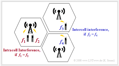
$\text{Example 2:}$ The graph illustrates both types of cell interference:
- In the left cell, there is "intracell interference" when the two frequencies $f_1$ and $f_2$ are identical.
- In contrast, there is "intercell interference" when the same frequencies are used in the right radio cells $(f_3 = f_4)$.
⇒ Intracell interference is usually more severe than intercell interference
- because of the close spacing of intracell interferers,
- that is, it causes a much smaller "'carrier-to-interference ratio" $\rm (CIR)$.
What is cell breathing?
In order to limit the influence of the interference power on the transmission quality, the so-called »cell breathing« is used in UMTS. This can be described as follows:
- If the number of active subscribers and thus the current interference power increases, the cell radius is reduced.
- Since fewer subscribers are now transmitting in the cell, the interfering influence of intracell interference is thus also reduced.
- The less loaded neighboring cell then steps in to supply the subscribers standing at the edge of a busy cell.
- For the supply of the users at the edge of a busy cell, a less busy neighboring cell steps in.
⇒ An alternative to "cell breathing" is to reduce the total transmitted power within the cell, which, however, also means a reduction in the transmission quality.
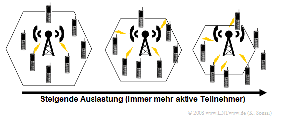
$\text{Example 3:}$ In the graph, we can see that the number of active subscribers $($per unit area$)$ in the coverage area increases from left to right.
- If one leaves the cell size the same, there are more active subscribers in the cell than before and accordingly the quality decreases significantly due to intracell interference.
- If, on the other hand, the cell size is reduced to the same extent as the number of subscribers increases, there are no more active subscribers in a cell than before $($according to this sketch: seven$)$ and the quality remains $($approximately$)$ the same
.
Handover in UMTS
In order to make the transition between different cells appear as uninterrupted as possible for mobile subscribers, a handover is used for circuit-switched UMTS services – as with GSM. A distinction is made between two types in UMTS:
- »Hard Handover«: Here the connection is switched hard to another node B at a certain point in time. This type of handover happens in the time division duplex mode $\rm (TDD)$ during the switchover between transmitter and receiver.
- »Soft Handover«: In this process, a mobile can communicate simultaneously with up to three base stations. The handover of a subscriber from one node B to another takes place gradually until the subscriber finally leaves this area. In this context, one speaks of "macrodiversity".
The downlink data
- is split in the radio network controller $\rm (RNC)$,
- broadcast over the participating base stations, and
- reassembled in the mobile station $($"Rake processing"$)$.
However, in the uplink:
- The transmitted data is received by all participating base stations.
- The soft combining of the data takes place in the radio network controller $\rm (RNC)$.
- This then forwards the data to the core network $\rm (CN)$.
A distinction is made between three special cases of "soft handover":
- With »Softer Handover« a subscriber is supplied via different paths of the same base station.
- on the other hand, »Intra-RNC Handover« involves supplying the subscribers via two different base stations connected to the same RNC. The combining and splitting of the data takes place in the common RNC.
- »Inter-RNC Handover« is present, if the subscriber is in an area managed by two adjacent radio network controllers:
- The first RNC ⇒ "Serving RNC" $\rm (SRNC)$ handles communications with the core network and is responsible for "Combining and Splitting".
- The second RNC ⇒ "Drift RNC" $\rm (GRNC)$ handles communications with the SRNC and with the node B it manages.
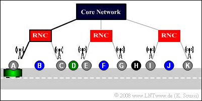
$\text{Example 4:}$ We assume the following scenario: The vehicle starts at $\rm A$, moves to the right, and passes various base stations, each connected to a radio network controller $\rm (RNC)$.
- At positions $\rm A$, $\rm C$, $\rm E$, $\rm G$, $\rm I$, $\rm K$: There is always only one RNC connection
⇒ no handover. - For $\rm B$, $\rm F$, $\rm J$: the vehicle is in contact with two base stations of the same RNC
⇒ "intra-RNC handover". - For $\rm D$ and $\rm H$: The vehicle is in contact with two base stations of two RNCs
⇒ "inter-RNC handover".
- However, (3) requires that the coordination of the two RNCs through the core network is functioning. Otherwise: "hard handover".
IP core networks
UMTS Release 5 introduced, among other things, »IP Core Networks«.
- In this case, both the user data and the control data are transmitted over an internal IP network.
- This means that both circuit-switched services and packet-switched services are provided on the basis of IP protocols.
The graph shows this network architecture in schematic form. Compared with the original UMTS network architecture $($Release 99$)$, the following nodes have been added to the network:
- The »Media Gateway« $\rm (MGW)$ is responsible for recovering voice packets converted to "'voice-over-IP" $\rm (VoIP)$ into conventional voice data.
- The »Home Subscriber Server« $\rm (HSS)$ combines the registers "HLR" and "VLR" known from UMTS Release 99.
- The »Call State Control Function« $\rm (CSCF)$ node is responsible for the overall control of the IP network in UMTS Release 5 and establishes the communication between CSCF node and subscriber via the "session initiation protocol" $\rm (SIP)$.
Major advantages of IP networks are:
- A forward-looking alternative to the previou design,
- a low-cost routing technology ⇒ large savings in switching equipment,
- great flexibility in the introduction of new services, and
- an ease of implementation of network monitoring techniques.
However, crucial disadvantages of this architecture $($ at 2011$)$ include:
- The cumbersome integration of second generation cellular infrastructure,
- the need for transition nodes to convert the data in so-called gateways, and
- the lack of a clear and reliable security concept.
Exercises for the chapter
Exercise 4.3: UMTS Access Level
Exercise 4.4: Cellular UMTS Architecture
