Contents
- 1 Improvements regarding speech coding
- 2 Application of the CDMA method to UMTS
- 3 Spreading codes and scrambling with UMTS
- 4 Channel coding for UMTS
- 5 Frequency responses and pulse shaping for UMTS
- 6 Modulation methods for UMTS
- 7 Single-user receiver
- 8 Rake receiver
- 9 Multi-user receiver
- 10 Near–far problem
- 11 Carrier-to-interference power ratio
- 12 Power and power control in UMTS
- 13 Link budget
- 14 UMTS radio resource management
- 15 Exercises for the chapter
- 16 Sources
Improvements regarding speech coding
In the chapter "Global System for Mobile Communications" $\rm (GSM)$ of this book, several speech codecs have already been described in detail.
$\text{Reminder:}$ A speech codec is used to reduce the data rate of a digitized speech or music signal.
- In the process, redundancy and irrelevance are removed from the original signal.
- The artificial word "codec" indicates that the same functional unit is used for both, encoding and decoding.
Among others, the "Adaptive Multi-Rate Codec" $\rm (AMR)$ based on $\rm ACELP$ $($"Algebraic Code Excited Linear Prediction"$)$ was introduced,
- which in the frequency range from $\text{300 Hz}$ to $\text{3400 Hz}$
- dynamically switches between eight different modes $($single codecs$)$
- of different data rate in the range of $\text{4. 75 kbit/s}$ to $\text{12.2 kbit/s}$.
These codecs are also supported in UMTS Release 99 and Release 4. Compared to the earlier speech codecs $($Full Rate, Half Rate, Enhanced Full Rate Vocoder$)$, they allow
- independence from channel conditions and network load,
- the ability to adapt data rates to conditions,
- improved flexible error protection in the event of more severe radio interference, and
- thereby providing better overall voice quality.
In 2001, the "3rd Generation Partnership Project" $\text{(3gpp)}$ and the "International Telecommuncation Union" $\text{(ITU)}$ specified the new voice codec »Wideband AMR« for UMTS Release 5. This is a further development of AMR and offers
- an extended bandwidth from $\text{50 Hz}$ to $\text{7 kHz}$
$($sampling frequency $\text{16 kHz})$,
- a total of nine modes between $\text{6.6 kbit/s}$ and $\text{23.85 kbit/s}$
$($of which only five modes are used$)$, and
- improved voice quality and better (more natural) sound.
$\text{Some features of wideband AMR}$
- Speech data is delivered to the codec as PCM encoded speech with $16\hspace{0.05cm}000$ samples per second.
- The speech coding is done in blocks of $\text{20 ms}$ and the data rate is adjusted every $\text{20 ms}$.
- The band $\text{(50 Hz}$ to $\text{7000 Hz})$ is divided into two sub-bands, which are encoded differently to allocate more bits to the subjectively important frequencies.
- The upper band $\text{(6400 Hz}$ to $\text{7000 Hz})$ is transmitted only in the highest mode $($with $\text{23.85 kbit/s)}$ .
- In all other modes, only frequencies $\text{50 Hz}$ to $\text{6400 Hz}$ are considered in encoding.
- Wideband AMR supports "discontinuous transmission"' $\rm (DTX)$. This feature means that transmission is paused during voice pauses, reducing both mobile station power consumption and overall interference at the air interface. This process is also known as "Source-Controlled Rate" $\rm (SCR)$.
- The "Voice Activity Detection" $\rm (VAD)$ determines whether speech is in progress or not and inserts a "silence descriptor frame" during speech pauses.
- The subscriber is suggested the feeling of a continuous connection by the decoder inserting synthetically generated "comfort noise" during speech pauses.
Application of the CDMA method to UMTS
UMTS uses the multiple access method "Direct Sequence Code Division Multiple Access" $\rm (DS-CDMA)$, which has already been discussed in the "PN modulation" chapter of the book "Modulation Methods".
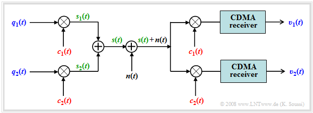
Here follows a brief summary of this method according to the diagram describing such a system in the equivalent low-pass range and highly simplified:
- The two data signals $q_1(t)$ and $q_2(t)$ are supposed to use the same channel without interfering with each other. The bit duration of each is $T_{\rm B}$.
- Each of the data signals is multiplied by an associated spreading code $c_1(t)$ resp. $c_2(t)$.
- The sum signal $s(t) = q_1(t) · c_1(t) + q_2(t) · c_2(t)$ is formed and transmitted.
- At the receiver, the same spreading codes $c_1(t)$ resp. $c_2(t)$ are added, thus separating the signals again.
- Assuming orthogonal spreading codes and a small AWGN noise, the two reconstructed signals at the receiver output are:
- $$v_1(t) = q_1(t) \ \text{and} \ v_2(t) = q_2(t).$$
- For AWGN noise signal $n(t)$ and orthogonal spreading codes, this does not change the error probability due to other participants.
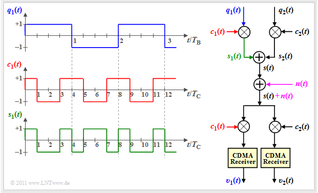
$\text{Example1:}$ The upper graph shows three data bits $(+1, -1, +1)$ of the rectangular signal $q_1(t)$ from subscriber 1, each with symbol duration $T_{\rm B}$.
- Here, the symbol duration $T_{\rm C}$ of the spreading code $c_1(t)$ ⇒ also called "chip duration" is smaller by a factor $4$.
- The multiplication $s_1(t) = q_1(t) · c_1(t)$ results in a chip sequence of length $12 · T_{\rm C}$.
One recognizes from this sketch that the signal $s_1(t)$ is of higher frequency than $q_1(t)$.
- This is why this modulation method is often also called "spread spectrum".
- The CDMA receiver reverses this "spreading". We refer to this "receiver-side spreading" as "despreading".
$\text{Summarizing:}$ By applying "Direct Sequence Code Division Multiple Access" $\rm (DS-CDMA)$ to a data bit sequence $q(t)$
- increases the bandwidth of $s(t) = q(t) \cdot c(t)$ by the »spreading factor« $J = T_{\rm B}/T_{\rm C}$ – this is equal to the number of "chips per bit";
- the chip rate $R_{\rm C}$ is greater than the bit rate $R_{\rm B}$ by a factor $J$;
- the bandwidth of the entire CDMA signal is greater than the bandwidth of each user by a factor $J$.
That is: $\text{In UMTS, the entire bandwidth is available to each subscriber for the entire transmission duration}$.
Recall: In GSM, both "Frequency Division Multiple Access" and "Time Division Multiple Access" are used as multiple access methods.
- Here, each subscriber has only a limited frequency band $\rm (FDMA)$, and
- he only has access to the channel within time slots $\rm (TDMA)$.
Spreading codes and scrambling with UMTS
The spreading codes for UMTS should
- be orthogonal to each other to avoid mutual interference between subscribers,
- allow a flexible realization of different spreading factors $J$.
⇒ The issue presented here is also illustrated by the German-language SWF applet "OVSF codes".
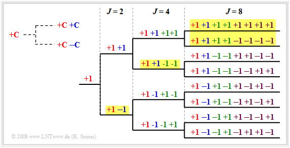
$\text{Example 2:}$ An example of this is the »orthogonal variable spreading factor« $\rm (OVSF)$, which provide codes of lengths from $J = 4$ to $J = 512$.
These can be created using a code tree, as shown in the diagram. Here, at each branch, two new codes are created from one code $C$:
- $(+C \ +\hspace{-0.1cm}C)$, and
- $(+C \ -\hspace{-0.1cm}C)$.
Note that no predecessor and successor of a code may be used.
- So in the drawn example, eight spreading codes with spreading factor $J = 8$ could be used.
- Also possible are the four codes with yellow background
- once with $J = 2$,
- once with $J = 4$, and
- twice with $J = 8$.
But the lower four codes with spreading factor $J = 8$ cannot be used, because they all start with "$+1 \ -\hspace{-0.1cm}1$", which is already occupied by the OVSF code with spreading factor $J = 2$.
To obtain more spreading codes and thus be able to supply more participants, after the band spreading with $c(t)$
- the sequence is chip-wise scrambled again with $w(t)$,
- without any further spreading.
The »scrambling code« $w(t)$ has same length and rate as the spreading code $c(t)$.
⇒ Scrambling causes the codes to lose their complete orthogonality; they are called "quasi-orthogonal".
- For these codes, although the "cross-correlation function" $\rm (CCF)$ between different spreading codes is non-zero.
- But they are characterized by a pronounced "auto-correlation function" $\rm (ACF)$ around zero, which facilitates detection at the receiver.
- Using quasi-orthogonal codes makes sense because the set of orthogonal codes is limited and scrambling allows also different users to use the same spreading codes.
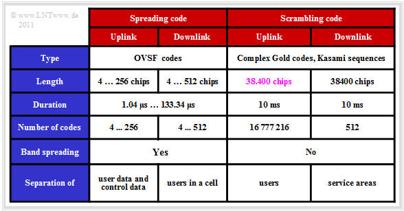
The table summarizes some data of spreading and scrambling codes.
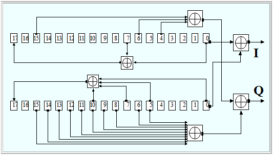
$\text{Example 3:}$ In UMTS, so-called »Gold codes« are used for scrambling. The graphic from [3gpp][1] shows the block diagram for the circuitry generation of such codes.
- Two different pseudonoise sequences of equal length $($here: $N = 18)$ are first generated in parallel using shift registers and added bitwise using "exclusive-or" gates.
- In the uplink, each mobile station has its own scrambling code and the separation of each channel is done using the same code.
- In contrast, in the downlink, each coverage area of a "Node B" has a common scrambling code.
Channel coding for UMTS
With UMTS, the EFR- and AMR-encoded voice data pass through a two-stage error protection $($similar to GSM$)$, consisting of
- formation of "cyclic redundancy check bits" $\rm (CRC)$,
- subsequent convolutional encoding.
However, these methods differ from those used for GSM in that they are more flexible, since for UMTS they have to take different data rates into account.
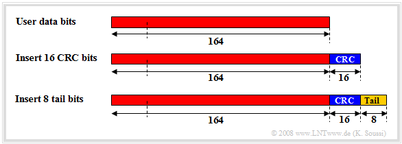
⇒ For »error detection«, eight, twelve, sixteen or $24$ CRC bits are formed depending on the size of the transport block $\text{(10 ms}$ or $\text{20 ms})$, and appended to it.
- Eight tail bits are also inserted at the end of each frame for synchronization purposes.
- The diagram shows a transport block of the DCH channel with $164$ user data bits, to which $16$ CRC bits and eight tail bits are appended.
⇒ For »error correction«, UMTS uses two different methods, depending on the data rate:
- For low data rates, "convolutional codes" with code rates $R = 1/2$ or $R = 1/3$ are used as with GSM. These are generated with eight memory elements of a feedback shift register $(256$ states$)$. The coding gain is approximately $4.5$ to $6$ dB with code rate $R = 1/3$ and at low error rates.
- For higher data rates, one uses "turbo codes" of rate $R = 1/3$. The shift register consists here of three memory cells, which can assume a total of eight states. The gain of turbo codes is larger by $2$ to $3$ dB than by convolutional codes and depends on the number of iterations. You need a processor with high processing power for this and there may be relatively large delays.
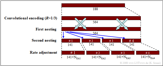
After channel coding, the data is fed to an "interleaver" as in GSM, in order to be able to resolve bundle errors caused by fading on the receiving side. Finally, for "rate matching" of the resulting data to the physical channel, individual bits are removed $($"puncturing"$)$ or repeated $($"repetition"$)$ according to a predetermined algorithm.
$\text{Example 4:}$ The graph first shows the increase in bits due to a convolutional or turbo code of rate $R =1/3$, where the $188$ bit time frame $($after the CRC checksum and tail bits$)$ becomes a $564$ bit frame.
- Followed by a first $($external$)$ nesting and then a second $($internal$)$ nesting.
- After this, the time frame is divided into four subframes of $141$ bits each, and these are then matched to the physical channel by rate matching.
Frequency responses and pulse shaping for UMTS
In this section, we assume the following block diagram of a binary system with ideal channel ⇒ $H_{\rm K}(f) = 1$.
In particular, let hold:
- The "transmitter pulse filter" converts the binary $\{0, \ 1\}$ data into physical signals. The filter is described by the frequency response $H_{\rm S}(f)$, which is identical in shape to the spectrum of a single transmitted pulse.
- In UMTS, the receiver filter $H_{\rm E}f) = H_{\rm S}(f)$ is matched to the transmitter $($"matched filter"$)$ and the overall frequency response $H(f) = H_{\rm S}(f) \cdot H_{\rm E}(f)$ satisfies the "first Nyquist criterion":
- $$ H(f) = H_{\rm CRO}(f) = \left\{ \begin{array}{c} 1 \\ 0 \\ \cos^2 \left( \frac {\pi \cdot (|f| - f_1)}{2 \cdot (f_2 - f_1)} \right)\end{array} \right.\quad \begin{array}{*{1}c} {\rm{for}} \\ {\rm{for}}\\ {\rm else }\hspace{0.05cm}. \end{array} \begin{array}{*{20}c} |f| \le f_1, \\ |f| \ge f_2.\\ \\\end{array}$$
This means: Consecutive pulses in time do not interfere with each other ⇒ no "intersymbol interference" $\rm (ISI)$ occur. The associated time function is:
- $$h(t) = h_{\rm CRO}(t) ={\rm sinc}(t/ T_{\rm C}) \cdot \frac{\cos(r \cdot \pi t/T_{\rm C})}{1- (2r \cdot t/T_{\rm C})^2}\hspace{0.4cm} \text{with } \hspace{0.4cm} r = \frac{f_2 - f_1}{f_2 + f_1}. $$
- "CRO" here stands for "raised cosine low-pass".
- The sum $f_1 + f_2$ is equal to the inverse of the chip duration $T_{\rm C} = 260 \ \rm ns$, so it is equal to $3.84 \ \rm MHz$.
- The "rolloff factor" has been determined to $r = 0.22$ for UMTS. The two "corner frequencies" are thus
- $$f_1 = {1}/(2 T_{\rm C}) \cdot (1-r) \approx 1.5\,{\rm MHz},$$
- $$f_2 ={1}/(2 T_{\rm C}) \cdot (1+r) \approx 2.35\,{\rm MHz}.$$
- The required bandwidth is $B = 2 \cdot f_2 = 4.7 \ \rm MHz$. Thus, there is sufficient bandwidth available for each UMTS channel with $5 \ \rm MHz$.
$\text{Conclusion:}$ The graph shows.
- on the left, the $($normalized$)$ Nyquist spectrum $H(f)$,
- on the right, the corresponding Nyquist pulse $h(t)$, whose zero crossings are equidistant with distance $T_{\rm C}$.
$\text{It should be noted:}$
- The transmission filter $H_{\rm S}(f)$ and the matched filter $H_{\rm E}(f)$ are each "root raised cosine".
- Only the product $H(f) = H_{\rm S}(f) \cdot H_{\rm E}(f)$ leads to the raised cosine. This also means:
- The impulse responses $h_{\rm S}(t)$ and $h_{\rm E}(t)$ by themselves do not satisfy the first Nyquist condition.
- Only the combination of the two $($in the time domain the convolution$)$ leads to the desired equidistant zeros.
Modulation methods for UMTS
The modulation techniques used in UMTS can be summarized as follows:
- In the downlink: "Quaternary Phase Shift Keying" is used for modulation both in "frequency division duplex" $\rm (FDD)$ and in "time division duplex"" $\rm (TDD)$.
- Here, user data $($DPDCH channel$)$ and control data $($DPCCH channel$)$ are multiplexed in time.
- With TDD, the signal is modulated in the uplink also by means of QPSK, but not with FDD.
- Here, a "dual channel binary phase shift keying" is used ⇒ different channels are transmitted in "in-phase" and "quadrature components".
- Thus, two chips are transmitted per modulation step. The gross chip rate is therefore twice the modulation rate of $3.84$ Mchip per second.
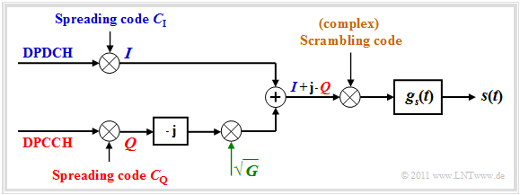
$\text{Example 5:}$ The graph shows in the equivalent low-pass domain this "I/Q multiplexing method", as it is also called:
- The spread useful data of the DPDCH channel is modulated onto the inphase component.
- The spread control data of the DPCCH channel is modulated onto the quadrature component.
- After modulation, the quadrature component is weighted by the root of the power ratio $G$ between the two channels to minimize the influence of power differences between $I$ and $Q$.
- Finally, the complex sum signal $(I +{\rm j} \cdot Q)$ is multiplied by a scrambling code that is also complex.
$\text{Conclusion:}$ An advantage of dual channel BPSK modulation is the possibility of usinglow-power amplifiers.
- But time division multiplexing of user and control data as in the uplink is not possible in the downlink.
- One reason for this is the use of "Discontinuous Transmission" $\rm (DTX)$ and the associated time constraints.
Single-user receiver
The task of a CDMA receiver is to separate and reconstruct the transmitted data of the individual subscribers from the sum of the spread data streams. A distinction is made between "single-user receivers" and "multi-user receivers".
In the UMTS downlink, it is always used a »single-user receiver«, since in the mobile station a joint detection of all subscribers would be too costly
- due to the large number of active subscribers
- as well as the length of the scrambling codes and the asynchronous operation.
Such a receiver consists of a bank of independent correlators.
- Each one of the total $J$ correlators belongs to a specific spreading sequence.
- The correlation is usually formed in a so-called "correlator database" by software.
Thereby one receives at the correlator output the sum of
- the "auto-correlation function" of the spreading code and
- the "cross-correlation function" of all other users with their own spreading code.
The graphic shows the simplest realization of such a receiver with matched filter.
- The received signal $r(t)$ is first multiplied by the spreading code $c(t)$ of the considered subscriber, which is called "despreading" $($yellow background$)$.
- Followed by convolution with the matched filter impulse response $($"Root Raised Cosine"$)$ to maximize SNR, and sampling in bit clock $(T_{\rm B})$.
- Finally, the threshold decision is made, which provides the sink signal $v(t)$ and thus the data bits of the considered subscriber.
$\text{Please note:}$
- For the AWGN channel, spreading at the transmitter and the matched despreading at the receiver have no effect on the bit error probability because of $c(t)^2 = 1$. As shown in $\text{Exercise 4.5}$, even with spreading/despreading at the optimal receiver, regardless of spreading factor $J$:
- $$p_{\rm B} = {\rm Q} \left( \hspace{-0.05cm} \sqrt { {2 \cdot E_{\rm B} }/{N_{\rm 0} } } \hspace{0.05cm} \right )\hspace{0.05cm}. $$
- This result can be justified as follows: The statistical properties of white noise $n(t)$ are not changed by multiplication with the $±1$ signal $c(t)$.
Rake receiver
Another receiver for single-user detection is the »rake receiver«, which leads to significant improvements for a multipath channel.
The diagram shows its setup for a two-way channel with
- a direct path with coefficient $h_0$ and delay time $τ_0$,
- an echo with coefficient $h_1$ and delay time $τ_1$.
For simplicity, the coefficients $h_0$ and $h_1$ are assumed to be real. Due to the representation in the equivalent low-pass domain, these could also be complex.
⇒ The task of the rake receiver is to concentrate the signal energies of all paths $($in this example only two$)$ to a single instant. It works accordingly like a "rake" for the garden.
If one applies a Dirac delta impulse at time $t = 0$ to the channel input, there will be three Dirac delta impulses at the output of the rake receiver:
- $$ s(t) = \delta(t) \hspace{0.3cm}\Rightarrow\hspace{0.3cm} y(t) = h_0 \cdot h_1 \cdot \delta(t - 2\tau_0) + (h_0^2 + h_1^2) \cdot \delta(t - \tau_0 - \tau_1)+ h_0 \cdot h_1 \cdot \delta(t - 2\tau_1) .$$
- The signal energy is concentrated at the time $τ_0 + τ_1$. Of the total four paths, two contribute $($middle term$)$.
- The Dirac delta functions at $2τ_0$ and $2τ_1$ do cause momentum interference. However, their weights are much smaller than those of the main path.
$\text{Example 6:}$ With channel parameters $h_0 = 0.8$ and $h_1 = 0.6$ the main path $($with weight $h_0)$ contains $0.82/(0.82 + 0.62) = 64\%$ of the total signal energy.
- With rake receiver and the same weights, the above equation is:
- $$ y(t) = 0.48 \cdot \delta(t - 2\tau_0) + 1.0 \cdot \delta(t - \tau_0 - \tau_1)+ 0.48 \cdot \delta(t - 2\tau_1) .$$
- The share of the main path in the total energy amounts in this simple example to ${1^2}/{(1^2 + 0.48^2 + 0.48^2)} ≈ 68\%.$
Rake receivers are preferred for implementation in mobile devices, but have a limited performance when there are many active participants.
- In a multipath channel with many $(M)$ paths, the Rake has also $M$ fingers.
- The main finger – also called "searcher" – is responsible for identifying and ranking the individual paths of multiple propagation.
- It searches for the strongest paths and assigns them to other fingers along with their control information.
- In the process, the time and frequency synchronization of all fingers is continuously compared with the control data of the received signal.
Multi-user receiver
In a single-user receiver, only the data signal of one subscriber is decided, while all other subscriber signals are considered as additional noise. However, the bit error rate of such a detector will be very large
- if there is large "intracell interference" $($many active subscribers in the considered radio cell$)$
- or large "intercell interference" $($highly interfering subscribers in neighboring cells$)$.
In contrast, »multi-user receivers« make a joint decision for all active subscribers.» Their characteristics can be summarized as follows:
- Such a multi-user receiver does not consider the interference from other participants as noise, but also uses the information contained in the interference signals for detection.
- The receiver is expensive to implement and the algorithms are extremely computationally intensive. It contains an extremely large correlator database followed by a common detector.
- The multi-user receiver must know the spreading codes of all active users. This requirement precludes use in the UMTS downlink $($i.e., at the mobile station$)$. In contrast, all subscriber-specific spreading codes are known a-priori to the base stations, so that multi-user detection is only used in the uplink.
- Some detection algorithms additionally require knowledge of other signal parameters such as energies and delay times. The common detector – the heart of the receiver – is responsible for applying the appropriate detection algorithm in each case.
- Examples of multi-user detection are "decorrelating detection" and "Interference Cancellation".
Near–far problem
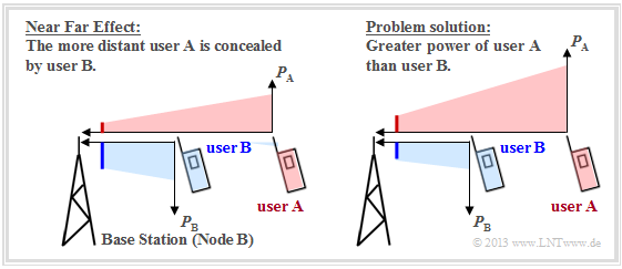
The "near-far problem" is exclusively an uplink problem, i.e., the transmission from mobile subscribers to a base station. We consider a scenario with two users at different distances from the base station according to the following graph. This can be interpreted as follows:
- If both mobile stations transmit with the same power, the received power of the red user $\rm A$ at the base station is significantly smaller than that of the blue user $\rm B$ $($left scenario$)$ due to path loss.
- In large macrocells, the difference can be as much as $100$ dB. As a result, the red signal is largely obscured by the blue.
- You can largely avoid the near-far problem if user $\rm A$ transmits with higher power than user $\rm B$, as indicated in the right scenario.
- Then, at the base station, the received power of both mobile stations is then $($almost$)$ equal.
Note: In an idealized system $($one-way channel, ideal A/D converters, fully linear amplifiers$)$ the transmitted data of the users are orthogonal to each other and one could detect the users individually even with very different received powers. This statement is true
- for UMTS $($multiple access: CDMA$)$ as well as
- for the 2G system GSM $($FDMA/TDMA$)$, and
- for the 4G system LTE $($TDMA/OFDMA$)$.
In reality, however, orthogonality is not always given due to the following reasons:
- Different receive paths ⇒ multipath channel,
- non-ideal characteristics of the spreading and scrambling codes in CDMA,
- asynchrony of users in the time domain $($basic propagation delay of paths$)$,
- asynchrony of users in the frequency domain $($non-ideal oscillators and Doppler shift due to mobility of users$)$.
Consequently, the users are no longer orthogonal to each other and the signal-to-noise ratio of the user to be detected with respect to the other users is not arbitrarily high:
- but for UMTS $($CDMA$)$ only approx. $15$ dB, with high-rate data transmission rather less.
Carrier-to-interference power ratio
The term "capacity" is generally understood to mean the number of available transmission channels per cell. However, since the number of subscribers is not strictly limited in UMTS unlike in GSM, no fixed capacity can be specified here.
- In perfect codes, the subscribers do not interfere with each other. Thus, the maximum number of users is determined solely by the spreading factor $J$ and the available number of mutually orthogonal codes, which, however, is also limited.
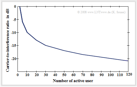
- More practical are non-perfect, only quasi-orthogonal codes. Here, the "capacity" of a radio cell is predominantly determined by the resulting interference or the "carrier-to-interference power ratio" $\rm (CIR)$.
As can be seen from this graph, CIR depends directly on the number of active participants. The more active subscribers there are, the more interference power is generated and the smaller the CIR becomes.
Furthermore, this decisive criterion for UMTS also depends on the following variables:
- The topology and user behavior $($number of services called up$)$,
- the spreading factor $J$ and the orthogonality of the used spreading code.
In order to limit the disturbing influence of the interference power on the transmission quality, there are two possible criteria:
»Cell breathing«: If the number of active subscribers increases significantly with UMTS, the cell radius is reduced and $($because of the now fewer subscribers in the cell$)$ also the current interference power is lower. A less loaded neighboring cell then steps in to supply the subscribers at the edge of the reduced cell.
»Power control«: If the total interference power within a radio cell exceeds a specified limit, the transmission power of all subscribers is reduced accordingly and/or the data rate is reduced, resulting in poorer transmission quality for all. More about this in the next section.
Power and power control in UMTS
The ratio between the signal power and the interference power is used as the controlled variable for power control in UMTS. There are differences between the "frequency division duplex" $\rm (FDD)$ and the "time division duplex" $\rm (TDD)$ modes.
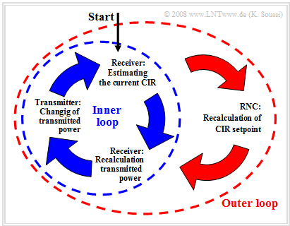
We take a closer look at the FDD power control. In the diagram you can see two different control loops:
- The »inner control loop« controls the transmitter power based on time slots, where one power command is transmitted in each time slot.
- The power of the transmitter is determined and changed using the CIR estimates in the receiver and the specifications of the "radio network controller" $\rm (RNC)$ from the outer control loop.
- The outer loop controls based on $10$ millisecond duration frames. It is implemented in the RNC and is responsible for determining the set point for the inner loop.
The FDD power control sequence is as follows:
- The RNC provides a carrier-to-interference ratio $\rm (CIR)$ setpoint.
- The receiver estimates the actual CIR value and generates control commands for the transmitter.
- The transmitter changes the transmitted power according to these control commands.
The principle of "power control in TDD mode" is similar to the control presented here for the FDD mode. In fact in the downlink direction they are practically identical.
$\text{Conclusion:}$ The »TDD power control« is much slower and thus less precise than in FDD.
- However, fast power control is not even possible in this case, since each participant has only a fraction of the time frame available for him.
Link budget
When planning UMTS networks, calculating the link budget is an important step. Knowledge of the link budget is required both for dimensioning the coverage areas and for determining the capacity and quality of service requirements.
The »objective of the link budget« is to calculate the maximum cell size considering the following criteria:
- Type and data rate of the services,
- topology of the environment,
- system configuration $($location and power of base stations, handover gain$)$,
- service requirements $($availability$)$,
- type of mobile station $($speed, power$)$,
- financial and economic aspects
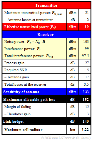
$\text{Example 7:}$ The calculation of the link budget is illustrated using the example of a voice transmission channel in the UMTS downlink. Regarding the exemplary numerical values, it should be noted:
- The transmitted power is $P_{\rm S} =19$ dBm, which corresponds to approx. $79$ mW.
Here, the antenna loss is considered to be $2$ dB. - The noise power $P_{\rm N} = 5 \cdot 10^{-11}$ mW ⇒ $P_{\rm N} = -103$ dBm
product of UMTS bandwidth and noise power density. - The interference power is $P_{\rm I} = -99$ dBm corresponding to $1.25 \cdot 10^{-10}$ mW.
- This gives the total interference power $P_{\rm N+I} = P_{\rm N} + P_{\rm I} = 1.25 \cdot 10^{-10}$ mW ⇒ $P_{\rm N+I} =- 97.5$ dBm.
- The antenna sensitivity results in $-97.5 - 27 + 5 - 17 + 3.5 = - 133$ dBm.
A large negative value here is "good". - Maximum allowable path loss should be as large as possible. Here $19 - (-133) = 152$ dB.
- The link budget includes the margin for fading and the handover gain, in the example: $140$ dB.
- The maximum cell radius can be determined from the link budget using an »empirical formula« of Okumura-Hata. It holds: $ {r}\ [{\rm km}] = 10^{({\rm LinkBudget}- 137)/35}= 10^{0.0857}\approx 1.22 . $
Notes:
- "$\rm dB$" denotes a logarithmic power specification, referenced to $1 \rm W$.
- In contrast "$\rm dBm$" refers to the power $1 \rm mW$.
UMTS radio resource management
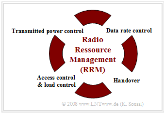
The central task of »radio resource management« $\rm (RRM)$ is the dynamic adaptation of radio transmission parameters to the current situation $($fading, mobile station movement, load, etc.$)$ with the aim to
- increase the transmission and subscriber capacity,
- improve the individual transmission quality, and
- use existing radio resources economically.
The main RRM mechanisms summarized in the diagram are explained below.
Transmit power control
The radio resource management attempts to keep the received power and thus the carrier-to-interference ratio $\rm (CIR)$ at the receiver constant, or at least to prevent it from falling below a specified limit.
An example of the need for power control is the "near-far problem", which is known to cause a disconnect.
The step size of the power control is $1 \ \rm dB$ or $2 \ \rm dB$, and the frequency of the control commands is $1500$ commands per second.
Regulation of data rate
UMTS allows an exchange between data rate and transmission quality, which can be realized by selecting the spreading factor. Doubling the spreading factor corresponds to halving the data rate and increases the quality by $3\ \rm dB$ $($spreading gain$)$.
Access control
To avoid overload situations in the overall network, a check is made before a new connection is established to see whether the necessary resources are available. If not, the new connection is rejected. This check is realized by estimating the transmission power distribution after the new connection is established.
Load control
This becomes active if an overload occurs despite access control. In this case, a handover to another base station is initiated and – if this is not possible – the data rates of certain nodes are lowered.
Handover
Finally, radio resource management is also responsible for handover to ensure uninterrupted connections. Mobile stations are assigned to the individual radio cells on the basis of CIR measurements.
Exercises for the chapter
Exercise 4.5: Pseudo Noise Modulation
Exercise 4.5Z: About Spread Spectrum with UMTS
Exercise 4.7: About the Rake Receiver
Sources
- ↑ 3gpp Group: UMTS Release 6 - Technical Specification 25.213 V6.4.0, Sept. 2005.

