Difference between revisions of "Aufgaben:Exercise 2.1: Linear? Or Non-Linear?"
From LNTwww
| Line 88: | Line 88: | ||
'''(3)''' <u>Approach 2</u> is correct: | '''(3)''' <u>Approach 2</u> is correct: | ||
| − | *The observer would realise that $S_2$ is a linearly distorting system | + | *The observer would realise that $S_2$ is a linearly distorting system. |
*For a non-distorting system, $z(t)$ would additionally have to include a direct (DC) component and a $10 \ \rm kHz$–, | *For a non-distorting system, $z(t)$ would additionally have to include a direct (DC) component and a $10 \ \rm kHz$–, | ||
*for a non-linearly distorting system, even larger frequency components $($at multiples of $10 \ \rm kHz)$. | *for a non-linearly distorting system, even larger frequency components $($at multiples of $10 \ \rm kHz)$. | ||
Revision as of 21:19, 9 September 2021
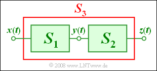
We consider the sketched arrangement with input $x(t)$ and output $z(t)$:
- The system $S_1$ is describable by the following equation:
- $$y(t) = x(t) + {1 \, \rm V}^{\rm -1} \cdot x^2(t) .$$
- Nothing else is known about the system $S_2$ with input $y(t)$ and output $z(t)$ .
- The system $S_3$ is the interconnection of $S_1$ and $S_2$.
An oscillation with frequency $f_0 = 5 \ \rm kHz$ is applied to the input:
- $$x(t) = {2 \, \rm V} \cdot {\rm cos}(2\pi f_0 t ) .$$
Hence, at the output of the overall system $S_3$ the following is obtained:
- $$z(t) = {1 \, \rm V} \cdot {\rm sin}(2\pi f_0 t ) .$$
Please note:
- The exercise belongs to the chapter Classification of Distortions.
- The following trigonometric relation is given:
- $$\cos^2(\alpha) = {1}/{2} \cdot \big[ 1 + \cos(2\alpha)\big].$$
Questions
Solution
(1) The following holds due to the characteristic curve with linear and quadratic components:
- $$y(t) = {2 \, \rm V} \cdot {\rm cos}(2\pi f_0 t ) + {1 \, \rm V}^{\rm -1} \cdot ({2 \, \rm V})^2 \cdot {\rm cos}^2(2\pi f_0 t ) = {2 \, \rm V} \cdot \big[ 1 + {\rm cos}(2\pi \cdot f_0 \cdot t ) +{\rm cos}(2\pi \cdot 2f_0 \cdot t ) \big].$$
- Therefore, the signal value 6 V occurs at time $t= 0$ .
(2) Alternatives 2 snd 3 are possible:
- An ideal system is out of the question because of $z(t) ≠ x(t)$ .
- With only one input frequency $(f_0 = 5 \ \rm kHz)$ in the test signal it is not possible to make a statement about whether a second frequency component with $f \ne f_0$ would also be attenuated by $\alpha = 0.5$ and delayed by $\tau = T_0/4 = 50 \ µ\rm s$ .
- If for the second frequency component $\alpha = 0.5$ and $\tau = T_0/4 = 50 \ µ \rm s$ arose as a result, a distortion-free system could exist.
- If for the second frequency component $\alpha \ne 0.5$ and/or $\tau \ne T_0/4$ arose as a result, then the system would be linearly distorting.
- The last alternative would have to be logically denied – although partially true – by the observer.
(3) Approach 2 is correct:
- The observer would realise that $S_2$ is a linearly distorting system.
- For a non-distorting system, $z(t)$ would additionally have to include a direct (DC) component and a $10 \ \rm kHz$–,
- for a non-linearly distorting system, even larger frequency components $($at multiples of $10 \ \rm kHz)$.
(4) In this case the following would hold:
- $$y(t) = {2 \, \rm V} \cdot \big[ 1 + {\rm cos}(2\pi \cdot 10 \ {\rm kHz} \cdot t ) +{\rm cos}(2\pi \cdot 20 \ {\rm kHz} \cdot t ) \big].$$
- That is: $Y(f)$ would have spectral lines at $f = 0$, $10 \ \rm kHz$ and $20 \ \rm kHz$ .
- However, the measurement described on the information page with $f_0 = 5 \ \rm kHz$ has shown that $H_2(f = 0) = H_2(f = 10 \ {\rm kHz}) = 0$ must hold.
- The only possible signal form is therefore
- $$z(t) = {2 \, \rm V} \cdot H_2 (f = {20 \, \rm kHz})\cdot {\rm cos}(2\pi \cdot {20 \, \rm kHz} \cdot t ) .$$
- So, approaches 1 and 3 are possible depending on whether the system $S_2$ suppresses or passes the frequency $20 \ {\rm kHz}$ .
