Difference between revisions of "Aufgaben:Exercise 2.2Z: Power Consideration"
m |
|||
| Line 3: | Line 3: | ||
}} | }} | ||
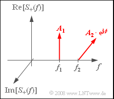
| − | [[File:P_ID991__Mod_Z_2_2.png|right|frame| | + | [[File:P_ID991__Mod_Z_2_2.png|right|frame|Analytical signal - line spectrum]] |
| − | + | Let us consider two harmonic oscillations | |
:$$ s_1(t) = A_1 \cdot \cos(\omega_{\rm 1} \cdot t ) \hspace{0.05cm},$$ | :$$ s_1(t) = A_1 \cdot \cos(\omega_{\rm 1} \cdot t ) \hspace{0.05cm},$$ | ||
:$$s_2(t) = A_2 \cdot \cos(\omega_{\rm 2} \cdot t + \phi) \hspace{0.05cm},$$ | :$$s_2(t) = A_2 \cdot \cos(\omega_{\rm 2} \cdot t + \phi) \hspace{0.05cm},$$ | ||
| − | + | where $f_2 ≥ f_1$ should hold for the frequencies. | |
| − | + | The graph shows the spectrum of the analytical signal $s_+(t)$, which is additively composed of the two components $s_{1+}(t)$ and $s_ {2+}(t)$ . | |
| − | + | Here, the transmission power $P_{\rm S}$ should be understood as the root mean square value of the signal $s(t)$ , averaged over the largest measurement period possible:: | |
:$$P_{\rm S} = \lim_{T_{\rm M} \rightarrow \infty}\hspace{0.1cm}\frac{1}{T_{\rm M}} \cdot \int_{0}^{ T_{\rm M}} {s^2(t) }\hspace{0.1cm}{\rm d}t \hspace{0.05cm}.$$ | :$$P_{\rm S} = \lim_{T_{\rm M} \rightarrow \infty}\hspace{0.1cm}\frac{1}{T_{\rm M}} \cdot \int_{0}^{ T_{\rm M}} {s^2(t) }\hspace{0.1cm}{\rm d}t \hspace{0.05cm}.$$ | ||
| − | + | According to this definition, if $s(t)$ describes a voltage waveform, $P_{\rm S}$ has unit $\rm V^2$ and refers to resistance $R = 1 \ \rm Ω$. Dividing by $R$ gives the physical power in $\rm W$. | |
| Line 21: | Line 21: | ||
| − | '' | + | ''Hints:'' |
| − | * | + | *This exercise belongs to the chapter [[Modulation_Methods/Double-Sideband_Amplitude_Modulation|Double-Sideband Amplitude Modulation]]. |
| − | * | + | *Particular reference is made to the chapter [[Modulation_Methods/Quality_Criteria|Quality Criteria]]. |
| − | * | + | *Use the numerical values $A_1 = 2\ \rm V$, $A_2 = 1 \ \rm V$ and $R = 50 \ \rm Ω$. |
Revision as of 13:23, 24 November 2021
Let us consider two harmonic oscillations
- $$ s_1(t) = A_1 \cdot \cos(\omega_{\rm 1} \cdot t ) \hspace{0.05cm},$$
- $$s_2(t) = A_2 \cdot \cos(\omega_{\rm 2} \cdot t + \phi) \hspace{0.05cm},$$
where $f_2 ≥ f_1$ should hold for the frequencies.
The graph shows the spectrum of the analytical signal $s_+(t)$, which is additively composed of the two components $s_{1+}(t)$ and $s_ {2+}(t)$ .
Here, the transmission power $P_{\rm S}$ should be understood as the root mean square value of the signal $s(t)$ , averaged over the largest measurement period possible::
- $$P_{\rm S} = \lim_{T_{\rm M} \rightarrow \infty}\hspace{0.1cm}\frac{1}{T_{\rm M}} \cdot \int_{0}^{ T_{\rm M}} {s^2(t) }\hspace{0.1cm}{\rm d}t \hspace{0.05cm}.$$
According to this definition, if $s(t)$ describes a voltage waveform, $P_{\rm S}$ has unit $\rm V^2$ and refers to resistance $R = 1 \ \rm Ω$. Dividing by $R$ gives the physical power in $\rm W$.
Hints:
- This exercise belongs to the chapter Double-Sideband Amplitude Modulation.
- Particular reference is made to the chapter Quality Criteria.
- Use the numerical values $A_1 = 2\ \rm V$, $A_2 = 1 \ \rm V$ and $R = 50 \ \rm Ω$.
Fragebogen
Musterlösung
- $$P_{\rm 1} = \lim_{T_{\rm M} \rightarrow \infty}\hspace{0.1cm}\frac{1}{T_{\rm M}} \cdot \int_{0}^{ T_{\rm M}} {A_1^2 \cdot \cos^2(\omega_{\rm 1} t + \phi_1) }\hspace{0.1cm}{\rm d}t \hspace{0.05cm}.$$
- Zur allgemeineren Berechnung ist die Phase $ϕ_1$ berücksichtigt, die hier eigentlich Null ist. Mit der Gleichung $\cos^{2}(α) = 0.5 · (1 + \cos(2α))$ ergibt sich:
- $$ P_{\rm 1} = \lim_{T_{\rm M} \rightarrow \infty}\hspace{0.1cm}\frac{1}{T_{\rm M}} \cdot \int_{0}^{ T_{\rm M}} {\frac{A_1^2}{2}}\hspace{0.1cm}{\rm d}t + \lim_{T_{\rm M} \rightarrow \infty}\hspace{0.1cm}\frac{1}{T_{\rm M}} \cdot \int_{0}^{ T_{\rm M}} {\frac{A_1^2}{2}\cdot \cos(2\omega_{\rm 1} t + 2\phi_1)}\hspace{0.1cm}{\rm d}t\hspace{0.05cm}.$$
- Der zweite Term liefert aufgrund der Integration über die Cosinusfunktion, der Division durch $T_{\rm M}$ und dem anschließenden Grenzübergang unabhängig von der Phase $ϕ_1$ keinen Beitrag. Damit erhält man:
- $$P_{\rm 1} = \frac{A_1^2}{2} = \frac{(2\,{\rm V})^2}{2} \hspace{0.15cm}\underline {= 2\,{\rm V}^2}\hspace{0.05cm}.$$
(2) Mit $R = 50\ \rm Ω$ erhält man für die „unnormierte” Leistung:
- $$P_{\rm 1} = \frac{2\,{\rm V}^2}{50\,{\rm \Omega}} \hspace{0.15cm}\underline {= 40\,{\rm mW}}\hspace{0.05cm}.$$
(3) Bereits in der Musterlösung zur Teilaufgabe (1) wurde gezeigt, dass die Phase keinen Einfluss auf die Leistung hat. Daraus folgt:
- $$P_{\rm 2} = \frac{A_2^2}{2} \hspace{0.15cm}\underline {= 0.5\,{\rm V}^2}\hspace{0.05cm}.$$
(4) Zur Leistungsberechnung muss über $s^{2}(t)$ gemittelt werden, wobei gilt:
- $$s^2(t) = s_1^2(t) + s_2^2(t) + 2 \cdot s_1(t) \cdot s_2(t).$$
- Aufgrund der Division durch die Messdauer $T_{\rm M}$ und des erforderlichen Grenzübergangs liefert der letzte Term unabhängig von der Phase $ϕ$ keinen Beitrag. Deshalb:
- $$P_{\rm S} = P_{\rm 1} + P_{\rm 2} \hspace{0.15cm}\underline {= 2.5\,{\rm V}^2}\hspace{0.05cm}.$$
(5) Mit $f_2 = f_1$ lautet das Spektrum des analytischen Signals:
- $$S_+(f) = (A_{\rm 1} + A_{\rm 2} \cdot {\rm e}^{{\rm j}\hspace{0.03cm} \cdot \hspace{0.03cm} \phi})\cdot \delta (f - f_1) \hspace{0.05cm}.$$
- Somit ergibt sich das Signal
- $$s(t) = A_3 \cdot \cos(\omega_{\rm 1} t + \phi_3) \hspace{0.05cm},$$
- dessen Phase $ϕ_3$ für die Leistungsberechnung keine Rolle spielt. Die Amplitude dieses Signals ist
- $$A_3 = \sqrt{ \left(A_1 + A_2 \cdot \cos(\phi)\right)^2 + A_2^2 \cdot \sin^2(\phi)} = \sqrt{ A_1^2 + A_2^2 + 2 \cdot A_1 \cdot A_2 \cdot \cos(\phi)}\hspace{0.05cm}.$$
- Für $ϕ = 0$ addieren sich die Amplituden skalar:
- $$A_3 = \sqrt{ A_1^2 + A_2^2 + 2 \cdot A_1 \cdot A_2 } = A_1 + A_2 = 3\,{\rm V}\hspace{0.3cm}\Rightarrow \hspace{0.3cm} P_{\rm S} \hspace{0.15cm}\underline {= 4.5\,{\rm V}^2}\hspace{0.05cm}.$$
- Dagegen addieren sich die Amplituden für $ϕ = 90^\circ$ vektoriell ⇒ gleiches Ergebnis wie in der Teilaufgabe (4):
- $$ A_3 = \sqrt{ A_1^2 + A_2^2 } = \sqrt{5}\,{\rm V}\hspace{0.3cm}\Rightarrow \hspace{0.3cm} P_{\rm S} = \frac{5\,{\rm V}^2}{2}\hspace{0.15cm}\underline {= 2.5\,{\rm V}^2}\hspace{0.05cm}.$$
- Für $ϕ = 180^\circ$ überlagern sich die Cosinusschwingungen destruktiv:
- $$A_3 = A_1 - A_2 = 1\,{\rm V}\hspace{0.3cm}\Rightarrow \hspace{0.3cm} P_{\rm S} \hspace{0.15cm}\underline {= 0.5\,{\rm V}^2}\hspace{0.05cm}.$$
