Difference between revisions of "Aufgaben:Exercise 2.4Z: Low-pass Influence with Synchronous Demodulation"
| Line 71: | Line 71: | ||
===Solution=== | ===Solution=== | ||
{{ML-Kopf}} | {{ML-Kopf}} | ||
| − | '''(1)''' <u>The first statement</u> is correct: | + | '''(1)''' <u>The first statement</u> is correct: |
| − | *The sink signal | + | *The sink signal $v(t)$ shown in the bottom graphic exactly matches the signal $b(t)$ given in the equation and thus also contains components around twice the carrier frequency. |
*The filter $H_{\rm E}(f)$ is either missing completely or its upper cutoff frequency $f_2$ is too high. | *The filter $H_{\rm E}(f)$ is either missing completely or its upper cutoff frequency $f_2$ is too high. | ||
| − | *Regarding the lower cutoff frequency $f_1$ | + | *Regarding the lower cutoff frequency $f_1$, the only statement possible is that it is smaller than the smallest frequency $\text{(2 kHz)}$ occurring in the signal $b(t)$. |
| − | *Whether or not a DC component is removed by the filter is unclear, since such a component is not present in the signal $b(t)$ | + | *Whether or not a DC component is removed by the filter is unclear, since such a component is not present in the signal $b(t)$. |
Revision as of 15:09, 5 December 2021
Let us consider the same communication system as in Exercise 2.4. But this time, we will assume perfect frequency and phase synchronization for the synchronous demodulator $\rm (SD)$ .
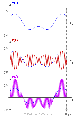
The source signal $q(t)$, the transmitted signal $s(t)$ and the signal $b(t)$ in the synchronous demodulator before the low-pass filter are given as follows:
- $$q(t) = q_1(t) + q_2(t)\hspace{0.2cm}{\rm with }$$
- $$q_1(t) = 2\,{\rm V} \cdot \cos(2 \pi \cdot 2\,{\rm kHz} \cdot t)\hspace{0.05cm},$$
- $$q_2(t) = 1\,{\rm V} \cdot \sin(2 \pi \cdot 5\,{\rm kHz} \cdot t)\hspace{0.05cm},$$
- $$s(t) = q(t) \cdot \sin(2 \pi \cdot 50\,{\rm kHz} \cdot t)\hspace{0.05cm},$$
- $$b(t) = s(t) \cdot 2 \cdot \sin(2 \pi \cdot 50\,{\rm kHz} \cdot t)\hspace{0.05cm}.$$
The graph shows the source signal $q(t)$ at the top and the transmission signal $s(t)$ in the middle.
The sink signal $v(t)$ is shown at the bottom (violet waveform).
- This obviously does not match the source signal (blue dashed curve).
- The reason for this undesired result $v(t) ≠ q(t)$ could be a missing or wrongly dimensioned low-pass filter.
In the subtasks (3) and (4) , a "trapezoidal low-pass filter" is used, whose frequency response is as follows:
- $$H_{\rm E}(f) = \left\{ \begin{array}{l} \hspace{0.25cm}1 \\ \frac{f_2 -|f|}{f_2 -f_1} \\ \hspace{0.25cm} 0 \\ \end{array} \right.\quad \quad \begin{array}{*{10}c} {\rm{f\ddot{u}r}} \\ {\rm{f\ddot{u}r}} \\ {\rm{f\ddot{u}r}} \\ \end{array}\begin{array}{*{20}c} {\hspace{0.94cm}\left| \hspace{0.005cm} f\hspace{0.05cm} \right| < f_1,} \\ {f_1 \le \left| \hspace{0.005cm}f\hspace{0.05cm} \right| \le f_2,} \\ {\hspace{0.94cm}\left|\hspace{0.005cm} f \hspace{0.05cm} \right| > f_2.} \\ \end{array}$$
Hints:
- This exercise belongs to the chapter Synchronous Demodulation.
- Particular reference is made to the page Block diagram and time domain representation.
- In contrast to Exercise 2.4 , $f_1$ and $f_2$ do not describe signal frequencies, but instead relate to the low-pass filter.
Questions
Solution
- The sink signal $v(t)$ shown in the bottom graphic exactly matches the signal $b(t)$ given in the equation and thus also contains components around twice the carrier frequency.
- The filter $H_{\rm E}(f)$ is either missing completely or its upper cutoff frequency $f_2$ is too high.
- Regarding the lower cutoff frequency $f_1$, the only statement possible is that it is smaller than the smallest frequency $\text{(2 kHz)}$ occurring in the signal $b(t)$.
- Whether or not a DC component is removed by the filter is unclear, since such a component is not present in the signal $b(t)$.
(2) Answers 1 and 3 are correct:
- A prerequisite for distortion-free demodulation is that all spectral components up to a certain frequency $f_1$ are transmitted equally and as unattenuated as possible, and all components at frequencies $f > f_2$ are completely suppressed.
- The rectangular and trapezoidal low-pass filters satisfy this condition.
(3) It must be ensured that the $\text{5 kHz}$ component still lies in the passband:
- $$f_{\text{1, min}}\hspace{0.15cm}\underline{ =5 \ \rm kHz}.$$
(4) All spectral components in the vicinity of twice the carrier frequency – more precisely between $\text{95 kHz}$ and $\text{ 105 kHz}$ – must be completely suppressed:
- $$f_{\text{2, max}}\hspace{0.15cm}\underline{ =95 \ \rm kHz}.$$
- Otherwise nonlinear distortion would arise.
(5) Answer 2 is correct:
- The cutoff frequency} $f_{\rm G} = \text{ 4 kHz}$ would result in (linear) distortions, since the $\text{5 kHz}$ component would be cut off.
- The lowpass with cutoff frequency $f_{\rm G} = \text{6 kHz}$ is preferable, since with $f_{\rm G} = \text{10 kHz}$ , more noise components would be superimposed on the useful signal $v(t)$.
