Difference between revisions of "Exercise 2.3: QAM Signal Space Assignment"
| Line 141: | Line 141: | ||
| − | [[File: | + | [[File:P_ID1978__Bei_A_2_3_Loesung.png|right|frame|$\rm256–QAM$: Vollständige Belegung des ersten Quadranten]] |
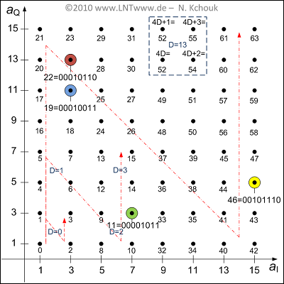
The final graph shows all the signal space points of the first quadrant, with the points labeled with the decimal values of the binary sequences. | The final graph shows all the signal space points of the first quadrant, with the points labeled with the decimal values of the binary sequences. | ||
Revision as of 15:12, 7 March 2023
In $\rm ADSL$ (Asymmetric Digital Subscriber Line), different transmission methods are applicable. For $\rm QAM$ as well as for $\rm CAP$ and $\rm DMT$ a signal space allocation takes place.
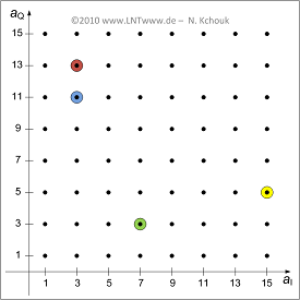
The graph shows the first quadrant of the considered signal space mapping. The four color-coded points are referred to in the exercise. It should be noted:
- The in-phase and quadrature coefficients $(a_{\rm I}, \ a_{\rm Q})$ can here respectively take the values $1, \ 3$, ... , $15$ . In other quadrants also the negative values $-1$, $-3$, ... , $-15$ are possible.
- Each $b$ bit is combined into a signal space point, identified by the coordinates $a_{\rm I}$ and $a_{\rm Q}$.
- If a bit sequence $(q_{b-1}, \ q_{b-2}$, ... , $q_{0})$ transmitted, the $\rm MSB$ (Most Significant Bits) $q_{b-1}$ and $q_{b-2}$ signify the sign of $a_{\rm I}$ and $a_{\rm Q}$, and hence the quadrant.
- If $q_{b-1} = 0$, then $a_{\rm I}$ is positive. In contrast $q_{b-1} = 1$ indicates a negative $a_{\rm I}$ . The same relationship exists between $q_{b-2}$ and $a_{\rm Q}$.
- The in-phase part $a_{\rm I}$ is given as the decimal value of the binary number $(q_{b-1}, \ q_{b-3}$, ... , $q_{1}, \ 1)$. Negative numbers are represented by the two's complement.
- The quadrature part $a_{\rm Q}$ is given as the decimal value of the binary number $(q_{b-2}, \ q_{b-4}$, ... , $q_{0}, \ 1)$. Negative numbers are also represented here by the two's complement.
The goal of this exercise is to map given bit sequences to the correct signal space point. The reverse assignment is also demonstrated.
Hint:
- This exercise belongs to the chapter "xDSL as Transmission Technology".
Questions
Solution
- The first quadrant includes $8 \cdot 8\ \underline{ = 64}$ possible points.
- Thus, it is a $4 \cdot 64 = 256$-QAM.
(2) It must hold $2^b = 256$. It follows that $\underline{b = 8}$.
(3) The correct solution is proposition 1:
- The $\underline{ {\rm MSB} \boldsymbol{00}}$ indicate that $a_{\rm I}$ and $a_{\rm Q}$ are positive and thus mark the first quadrant considered here.
- Correspondingly, $\boldsymbol{10}$ ⇒ 2nd quadrant, $\boldsymbol{11}$ ⇒ 3rd quadrant, $\boldsymbol{01}$ ⇒ 4th quadrant.
(4) According to the specification, the in-phase fraction is negative $(q_{7} = \boldsymbol{1})$.
- From $\boldsymbol{10011}_{\rm binary} = 19_{\rm dec}$ we get the two's complement $19 - 32= -13$.
- The quadrature part is given by $\boldsymbol{01011}_{\rm binary} = 11:$
- $$\underline{a_{\rm I} = -13,\hspace{0.2cm}a_{\rm Q} = +11} \hspace{0.05cm}.$$
(5) The correct solution is proposed solution 3:
- According to the specification, it must be:
- $$ \ \ \ \ a_{\rm I} = 3\text{:} \ \ \ \ q_{5} = \boldsymbol{0}, \ q_{3} = \boldsymbol{0}, \ q_{1} = \boldsymbol{1} \Rightarrow \boldsymbol{0011}_{\rm binary} = 3,$$
- $$ \ \ \ a_{\rm Q} = 13\text{:} \ \ \ \ q_{4} = \boldsymbol{1}, q_{2} = \boldsymbol{1}, q_{0} = \boldsymbol{0} \Rightarrow \boldsymbol{1101}_{\rm binary} = 13.$$
From this follows a total of: $\langle \hspace{0.05cm} q_{7}, \ q_{6}, \ q_{5}$, ... , $q_{1}, \ q_{0} \hspace{0.05cm} \rangle = \boldsymbol{0001\hspace{0.05cm}0110}.$
(6) Correct is the proposed solution 2:
- Compared to the last exercise, there is no change with respect to $a_{\rm I}$.
- On the other hand now
- $$a_{\rm Q} = 11\text{:} q_{4} = \boldsymbol{1}, q_{2} = \boldsymbol{0}, q_{0} = \boldsymbol{1} \Rightarrow \boldsymbol{1011}_{\rm binary} = 11.$$
From this follows a total of: $\langle \hspace{0.05cm}q_{7}, \ q_{6}, \ q_{5}$, ... , $q_{1}, \ q_{0} \hspace{0.05cm} \rangle = \boldsymbol{0001\hspace{0.05cm}0010}.$
(7) There is no Gray encoding because the two adjacent signal space points "red" and "blue" differ by more than one bit.
(8) Correct here is the proposed solution 1:
- For Gray coding, each symbol error results in only a single bit error.
- For the bit error probability, we get $p_{\rm B} = p_{\rm S}/b$, since the number of transmitted bits is greater than the number of QAM symbols by a factor of $b$.
- With other encoding, this minimum value is not reached.
The final graph shows all the signal space points of the first quadrant, with the points labeled with the decimal values of the binary sequences.
The thinly drawn lines indicate a second approach to determining signal space occupancy, which is explained in the "theory section".

