Exercise 4.3: Subcarrier Mapping
From LNTwww
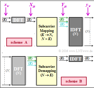
The diagram shows two transmission schemes that play a role in connection with Long Term Evolution $\rm (LTE)$. These block diagrams are referred here neutrally as "arrangement $\rm A$" or "arrangement $\rm B$".
- The light grey blocks represent the transition from the time to the frequency domain.
- The dark grey blocks represent the transition from the frequency to the time domain.
We refer here to the following links:
- Discrete Fourier Transform ⇒ $\rm DFT$,
- Inverse Discrete Fourier Transform ⇒ $\rm IDFT$.
For the number of interpolation points of DFT and IDFT, realistic numerical values of $K = 12$ and $N = 1024$ are assumed.
- The value $K = 12$ results from the fact that the symbols are "mapped" to a certain bandwidth by the subcarrier mapping . The smallest addressable block is $180 \ \rm kHz$ for LTE. With the subcarrier spacing of $15 \ \rm kHz$ $K = 12$ results.
- With the number of interpolation points $N$ of the IDFT $($with arrangement $\rm A)$ , up to $J = N/K$ users can thus be served simultaneously. For subcarrier mapping , there are three different approaches with DFDMA, IFDMA and LFDMA.
- The first two users are shown in green and turquoise in the diagram. In subtask (5) you are to decide whether the sketch applies to DFDMA, IFDMA or LFDMA.
Note:
- The task belongs to the chapter The Application of OFDMA and SC-FDMA in LTE.
Questions
Solution
(1) Proposed solution 2 is correct:
- Both arrangements show Single Carrier Frequency Division Multiple Access (SC–FDMA), recognisable by the DFT and IDFT blocks.
- The advantage over Orthogonal Frequency Division Multiple–Access (OFDMA) is the more favourable Peak–to–Average Power–Ratio (PAPR).
- A large PAPR means that the amplifiers must be operated below the saturation limit and thus at poorer efficiency in order to prevent excessive signal distortion.
- A lower PAPR also means longer battery life, an extremely important criterion for smartphones.
- This is why SC-FDMA is used in the LTE uplink. For the downlink, the aspect mentioned here is less significant.
(2) Proposed solutions 1 and 2 are correct:
- While in OFDMA the data symbols to be transmitted directly generate the various subcarriers, in SC-FDMA a block of data symbols is first transformed into the frequency domain using DFT.
- To be able to transmit multiple users, $N > K$ must apply. An input block of a user thus consists of $K$ bits. It is thus obvious that arrangement $\rm A$ applies to the transmitter.
- Arrangement $\rm B$ , on the other hand, describes the receiver of the LTE uplink and not the transmitter.
(3) Both statements are correct:
- The measures are necessary to be able to process a continuous bit stream at the transmitter or to ensure a continuous bit stream at the receiver as well.
(4) The DFT also generates $K$ spectral values from $K$ input values.
- The subcarrier–mapping does not change anything.
- Further users also occupy $K$ (bits) of the total of $N$ (bits).
- Thus $J = N/K = 1024/12 = 85.333$ ⇒ $J \ \underline{= 85}$ users can be supplied.
(5) Proposed solution 3 is correct:
- The graph conforms to the current 3gpp specification, which provides for Localized Mapping.
- Here, the $K$ modulation symbols are assigned to adjacent subcarriers.
(6) Proposed solutions 2 and 3 are correct:
- The realisation of DFT or IDFT as an (inverse) Fast Fourier Transform is only possible if the number of interpolation points is a power of two.
- For example, for $N = 1024$, but not for $K = 12$.
