Exercise 2.11: Envelope Demodulation of an SSB Signal
Let us consider the transmission of the cosine signal
- $$ q(t) = A_{\rm N} \cdot \cos(\omega_{\rm N} \cdot t)$$
according to the modulation method $\rm USB–AM$ ("upper-sideband amplitude modulation") with carrier. At the receiver, the high frequency range (HF) is reset to the low frquency range (LF) with an envelope demodulator.
The channel is assumed to be ideal such that the received signal $r(t)$ is identical to the transmitted signal $s(t)$ . With the sideband-to-carrier ratio
- $$ \mu = \frac{A_{\rm N}}{2 \cdot A_{\rm T}}$$
the equivalent low-pass signal (German: "äquivalentes Tiefpass-Signal" ⇒ subscript: "TP") can be written as:
- $$r_{\rm TP}(t) = A_{\rm T} \cdot \left( 1 + \mu \cdot {\rm e}^{{\rm j} \hspace{0.03cm}\cdot \hspace{0.03cm}\omega_{\rm N}\cdot \hspace{0.03cm}\hspace{0.03cm}t} \right) \hspace{0.05cm}$$
The envelope – i.e., the magnitude of this complex signal – can be determined by geometric considerations. Independent of the parameter $μ$, one obtains:
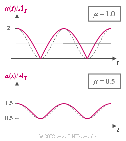
- $$a(t ) = A_{\rm T} \cdot \sqrt{1+ \mu^2 + 2 \mu \cdot \cos(\omega_{\rm N} \cdot t)}\hspace{0.05cm}.$$
The time-independent envelope $a(t)$ for $μ = 1$ and $μ = 0.5$ is shown in the graph. In each case, the amplitude-matched cosine oscillations, which would be a prerequisite for distortion-free demodulation, are plotted as dashed comparison curves.
- The periodic signal $a(t)$ can be approximated by a Fourier series :
- $$a(t ) = A_{\rm 0} + A_{\rm 1} \cdot \cos(\omega_{\rm N} \cdot t) + A_{\rm 2} \cdot \cos(2\omega_{\rm N} \cdot t)+ A_{\rm 3} \cdot \cos(3\omega_{\rm N} \cdot t)\hspace{0.05cm}+\text{...}$$
- The Fourier coefficients were determined using a simulation program. With $μ = 1$ the following values were obtained:
- $$A_{\rm 0} = 1.273\,{\rm V},\hspace{0.3cm} A_{\rm 1} = 0.849\,{\rm V},\hspace{0.3cm}A_{\rm 2} = -0.170\,{\rm V},\hspace{0.3cm} A_{\rm 3} = 0.073\,{\rm V},\hspace{0.3cm}A_{\rm 4} = 0.040\,{\rm V} \hspace{0.05cm}.$$
- Accordingly, for $μ = 0.5$, the simulation yielded:
- $$A_{\rm 0} = 1.064\,{\rm V},\hspace{0.3cm} A_{\rm 1} = 0.484\,{\rm V},\hspace{0.3cm}A_{\rm 2} = 0.058\,{\rm V} \hspace{0.05cm}.$$
- The values not given here can be ignored when calculating of the distortion factor.
- The sink signal $v(t)$ is obtained from $a(t)$ as follows:
- $$v(t) = 2 \cdot \big [a(t ) - A_{\rm 0} \big ] \hspace{0.05cm}.$$
- The factor of $2$ corrects for the amplitude loss due to "single-sideband amplitude modulation", while the subtraction of the DC signal coefficient $A_0$ takes into account the influence of the high-pass within the envelope demodulator.
- In questions (1) to (3), it is assumed that $A_{\rm N} = 2 \ \rm V$, $A_{\rm T} = 1 \ \rm V$ ⇒ $μ = 1$,
whereas from question (4), $A_{\rm N} = A_{\rm T} = 1 \ \rm V$ should apply for the parameter $μ = 0.5$.
Hints:
- This exercise belongs to the chapter Single-Sideband Modulation.
- Particular reference is made to the page Sideband-to-carrier ratio.
- Also compare your results to the rule of thumb which states that
"for the envelope demodulation of an SSB-AM signal with sideband-to-carrier ratio $μ$, the distortion factor is $K ≈ μ/4$".
Questions
Solution
- $$ a_{\rm max} = A_{\rm T} \cdot \sqrt{1+ \mu^2 + 2 \mu}= A_{\rm T} \cdot (1+ \mu) = 2\,{\rm V} \hspace{0.05cm},$$
- $$a_{\rm min} = A_{\rm T} \cdot \sqrt{1+ \mu^2 - 2 \mu}= A_{\rm T} \cdot (1- \mu) = 0 \hspace{0.05cm}.$$
- For the two extreme values of the sink signal it follows:
- $$ v_{\rm max} = 2 \cdot [a_{\rm max} - A_{\rm 0}] = 2 \cdot [2\,{\rm V} - 1.273\,{\rm V}] \hspace{0.15cm}\underline {=1.454\,{\rm V}}\hspace{0.05cm},$$
- $$ v_{\rm min} = -2 \cdot A_{\rm 0} \hspace{0.15cm}\underline {= -2.546\,{\rm V}}\hspace{0.05cm}.$$
(2) Ignoring the Fourier coefficients $A_5$, $A_6$, etc., we obtain:
- $$K = \frac{\sqrt{A_2^2 + A_3^2+ A_4^2 }}{A_1}= \frac{\sqrt{0.170^2 + 0.073^2 + 0.040^2 }{\,\rm V}}{0.849\,{\rm V}}\hspace{0.15cm}\underline { \approx 22.3 \%}.$$
- Here, the approximation $K ≈ μ/4$ yields the value $25\%$.
(3) Only the first answer is correct.
- Due to the high-pass within the envelope demodulator, the DC signal component would also be equal to zero if no distortions were present.
(4) Like in subtask (1) here it holds that:
- $$v_{\rm max} = 2 \cdot [a_{\rm max} - A_{\rm 0}] = 2 \cdot [1.5\,{\rm V} - 1.064\,{\rm V}] \hspace{0.15cm}\underline {= 0.872\,{\rm V}}\hspace{0.05cm},$$
- $$ v_{\rm min} = -2 \cdot A_{\rm 0} \hspace{0.15cm}\underline {= -2.128\,{\rm V}}\hspace{0.05cm}.$$
(5) A smaller sideband-to-carrier ratio also results in a smaller distortion factor:
- $$K = \frac{0.058{\,\rm V}}{0.484\,{\rm V}}\hspace{0.15cm}\underline { \approx 12 \%}.$$
- The simple approximation $K ≈ μ/4$ yields here $12.5\%$.
- It can be concluded that the above rule of thumb is more accurate for smaller values of $μ$.
(6) Thus, the distortion factor is largest when one of the sidebands is entirely cut out.
- However, since the envelope demodulator has no information to distinguish between
- a SSB–AM, or
- a DSB-AM which has been extremely affected by the channel,
- $K_{\rm max} ≈ μ/4$ simultaneously gives an upper bound for the DSB-AM.
- A comparison of the parameters $m = A_{\rm N}/A_{\rm T}$ and $μ = A_{\rm N}/(2A_{\rm T})$ leads to the result:
- $$K_{\rm max} = \frac{\mu}{4} = \frac{m}{8} \hspace{0.15cm}\underline {=6.25 \%}.$$
