Exercise 3.4Z: Continuous Phase Frequency Shift Keying
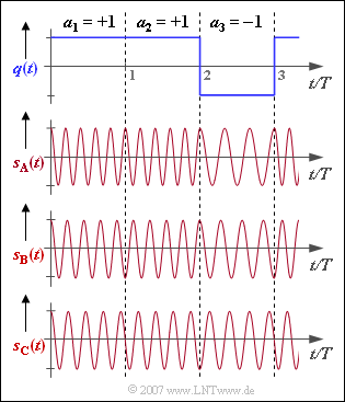
The graph shows three frequency shift keying $\rm (FSK)$ transmitted signals which differ with respect to the frequency deviation $\Delta f_{\rm A}$ distinguish and thus also by their modulation index
- $$h = 2 \cdot \Delta f_{\rm A} \cdot T.$$
The digital source signal $q(t)$ underlying the signals $s_{\rm A}(t), s_{\rm B}(t)$ and $s_{\rm C}(t)$ is shown above. All considered signals are normalized to amplitude $1$ and time duration $T$ and based on a cosine carrier with frequency $f_{\rm T}$.
With binary FSK $($"Binary Frequency Shift Keying"$)$ only two different frequencies occur, each of which remains constant over a bit duration:
- $f_{1}$ $($if $a_{\nu} = +1)$,
- $f_{2}$ $($if $a_{\nu} = -1)$.
If the modulation index is not a multiple of $2$, continuous phase adjustment is required to avoid phase jumps. This is called "Continuous Phase Frequency Shift Keying" $(\text{CP-FSK)}$.
An important special case is represented by binary FSK with modulation index $h = 0.5$ which is also called "Minimum Shift Keying" $(\rm MSK)$. This will be discussed in this exercise.
Hints:
- This exercise belongs to the chapter "Radio Interface".
- Reference is made in particular to the section "Continuous phase adjustment with FSK.
Questions
Solution
- Generally nonlinear FSK can only be demodulated coherently, while MSK can also use a noncoherent demodulation method.
- Compared to QPSK with coherent demodulation, MSK requires $3 \ \rm dB$ more $E_{\rm B}/N_{0}$ (energy per bit related to the noise power density) for the same bit error rate.
- The first zero in the power density spectrum occurs later in MSK than in QSPK, but it shows a faster asymptotic decay than in QSPK.
- The constant envelope of MSK means that nonlinearities in the transmission line do not play a role. This allows the use of simple and inexpensive power amplifiers with lower power consumption and thus longer operating times of battery-powered devices.
(2) One can see from the graph five and three oscillations per symbol duration, respectively:
- $$f_{\rm 1} \cdot T \hspace{0.15cm} \underline {= 5}\hspace{0.05cm},\hspace{0.2cm}f_{\rm 2} \cdot T \hspace{0.15cm} \underline { = 3}\hspace{0.05cm}.$$
(3) For FSK with rectangular pulse shape, only the two instantaneous frequencies $f_{1} = f_{\rm T} + \Delta f_{\rm A}$ and $f_{2} = f_{\rm T} - \Delta f_{\rm A}$ occur.
- With the result from (2) we thus obtain:
- $$f_{\rm T} \ = \ \frac{f_{\rm 1}+f_{\rm 2}}{2}\hspace{0.3cm}\Rightarrow \hspace{0.3cm}f_{\rm T} \cdot T \hspace{0.15cm} \underline {= 4}\hspace{0.05cm},$$
- $$ \Delta f_{\rm A} \ = \ \frac{f_{\rm 1}-f_{\rm 2}}{2}\hspace{0.3cm}\Rightarrow \hspace{0.3cm}\Delta f_{\rm A} \cdot T \hspace{0.15cm} \underline { = 1}\hspace{0.05cm},$$
- $$h \ = \ 2 \cdot \Delta f_{\rm A} \cdot T \hspace{0.15cm} \underline {= 2} \hspace{0.05cm}.$$
(4) From the graph one can see the frequencies $f_{1} \cdot T = 4.5$ and $f_{2} \cdot T = 3.5$.
- This results in the frequency deviation $\Delta f_{\rm A} \cdot T = 0.5$ and the modulation index $\underline{h = 1}$.
(5) Here the two (normalized) frequencies $f_{1} \cdot T = 4.25$ and $f_{2} \cdot T = 3.75$ occur,
- which results in the frequency deviation $\Delta f_{\rm A} \cdot T = 0.25$ and the modulation index $\underline{h = 0.5}$ can be calculated.
(6) Correct are the solutions 2 and 3:
- Only at $s_{\rm A}(t)$ was no phase adjustment made.
- Here, the signal waveforms in the region of the first and second bit ($a_{1} = a_{2} = +1$) are each cosinusoidal like the carrier signal (with respect to the symbol boundary).
- In contrast, in the second symbol of $s_{\rm B}(t)$ a minus-cosine-shaped course (initial phase $\phi_{0} = π$ corresponding to $180^\circ$) can be seen and in the second symbol of $s_{\rm C}(t)$ a minus-sine-shaped course ($\phi_{0} = π /2$ or $90^\circ$).
- For $s_{\rm A}(t)$ the initial phase is always $0$, for $s_{\rm B}(t)$ either $0$ or $π$, while for the signal $s_{\rm C}(t)$ with modulation index $h = 0.5$ a total of four initial phases are possible: $0^\circ, \ 90^\circ, \ 180^\circ$ and $270^\circ$.
(7) Correct is the last proposed solution, since for this signal $h = 0.5$ holds.
- This is the smallest possible modulation index for which there is orthogonality between $f_{1}$ and $f_{2}$ within the symbol duration $T$.
