Exercise 1.4: AMI and MMS43 Code
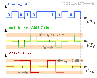
Two different ternary transmission codes are used with ISDN, which are to be clarified in the diagram at an exemplary binary input signal.
The upper diagram shows 12 bits $($each with the bit duration $T_{\rm B})$.
- On the $\rm S_{0}$ interface (between NTBA and terminal equipment) the modified AMI code is used. The difference to the conventional AMI code is the swapping $0 \Leftrightarrow 1$ of the binary input signal.
- In contrast, the MMS43 code (Modified Monitoring Sum 4B3T) is used on the $\rm U_{K0}$ interface, where four binary symbols are replaced by three ternary symbols $($voltage values $0 \ {\rm V}, +2.5 \ {\rm V}$ and $-2.5 \ {\rm V})$. The assignment is done depending on the previously coded symbols.
Notes:
- The exercise belongs to the chapter "ISDN Basic Access".
- Information on the MMS43 code can be found in the chapter "Block Coding with 4B3T Codes" of the book "Digital Signal Transmission".
- Information on the AMI code can be found in the chapter "Symbolwise Coding with Pseudo-Ternary Codes" of the same book.
Questions
Musterlösung
(1) Richtig sind die zwei ersten Aussagen:
- Der modifizierte AMI–Code ist ein so genannter Pseudo–Ternärcode mit $T_{\rm S} = T_{\rm B}$ und symbolweiser Codierung.
- Die angegebenen Zuordnungen gelten für den herkömmlichen AMI–Code.
- Dagegen wird beim modifizierten AMI–Code die binäre „1” durch den Spannungswert $0 \ \rm V$ repräsentiert und die binäre „0” alternierend durch $+s_{0}$ bzw. $-s_{0}$, wobei für $s_{0} = 0.75 \ \rm V$ zu setzen ist.
(2)
- Die äquivalente Bitrate des AMI–codierten Signals beträgt $R_{\rm C} = {\rm log_2}\hspace{0.05cm}(3)/T_{\rm S}$; die Bitrate des redundanzfreien binären Quellensignals ist gleich $R_{\rm B} = 1/T_{\rm B}$.
- Mit $T_{\rm S} = T_{\rm B}$ erhält man entsprechend dem Kapitel Grundlagen der codierten Übertragung des Buches „Digitalsignalübertragung” für die (relative) Redundanz des modifizierten AMI–Codes:
- $$r_{\rm AMI} = \frac{R_{\rm C}-R_{\rm B}}{R_{\rm C}} = 1 - \frac{1}{{\rm ld}\,(3)} \hspace{0.15cm}\underline{\approx 36.9\,\%} \hspace{0.05cm}.$$
(3)
- Unter Verwendung des Einheitswiderstandes $R = 1 \ \rm \Omega $ gilt für die Sendeleistung (mit der Einheit $\rm V^{2}$):
- $$P_{\rm S,\,AMI} = {1}/{2} \cdot {s_0}^2 = {1}/{2} \cdot {0.75\,{\rm V}}^2 \approx 0.28\,{\rm V^2} \hspace{0.05cm}.$$
- Hierbei ist berücksichtigt, dass das AMI–codierte Signal in der Hälfte der Zeit gleich $0 \ \rm V$ ist.
- Bei Berücksichtigung des Widerstandes $R = 100 \ \rm \Omega$ ergibt sich schließlich:
- $$P_{\rm S,\,AMI} = \frac{0.28\,{\rm V^2}}{100\,\Omega} \hspace{0.15cm}\underline{ = 2.8\,{\rm mW}} \hspace{0.05cm}.$$
(4) Der MMS43–Code arbeitet tatsächlich blockweise, wobei $m_{q} = 4 \ \rm Binärsymbole$ durch $m_{c} = 3 \ \rm Ternärsymbole$ ersetzt werden:
- $$4 \cdot T_{\rm B} = 3 \cdot T_{\rm S}\hspace{0.3cm}\Rightarrow \hspace{0.3cm} T_{\rm S} = {4}/{3} \cdot T_{\rm B} \hspace{0.05cm}.$$
- Das heißt: Der erste Lösungsvorschlag trifft nicht zu ebenso wie der letzte. Richtig ist nur der Vorschlag 2:
- Bei Blockcodierung kann das Binärsymbol „0” nicht einheitlich durch das gleiche Codesymbol ersetzt werden.
- Vielmehr lässt sich die Codierung wie folgt beschreiben, wenn man zu Beginn von der laufenden digitalen Summe ${\it \Sigma}_{0} = 0$ ausgeht (siehe Grafik auf der Angabenseite):
- $$\mathbf{0 1 0 1} \hspace{0.1cm} \ \Rightarrow \ \hspace{0.1cm}\mathbf{0 + +}\hspace{0.2cm}({\it \Sigma}_1 = 2)\hspace{0.05cm},$$
- $$ \mathbf{0 1 1 1} \hspace{0.1cm} \ \Rightarrow \ \hspace{0.1cm}\mathbf{- \,0 \,\,+}\hspace{0.2cm}({\it \Sigma}_2 = 2)\hspace{0.05cm},$$
- $$ \mathbf{0 1 0 1} \hspace{0.1cm} \ \Rightarrow \ \hspace{0.1cm}\mathbf{- \,0\,\,\, 0}\hspace{0.2cm}({\it \Sigma}_3 = 1) \hspace{0.05cm}.$$
In der Aufgabe 1.4Z wird der MMS43–Code noch ausführlicher behandelt.
(5) Der MMS43–Code gehört zur Klasse der 4B3T–Codes. Für diese gilt:
- $$R_{\rm B} = \frac{1}{T_{\rm B}}, \hspace{0.2cm} R_{\rm C} = \frac{{\rm ld}\,(3)}{T_{\rm S}}\hspace{0.3cm} \Rightarrow \hspace{0.3cm}r_{\rm MMS43} = 1 - \frac{R_{\rm B}}{R_{\rm C}} = 1 - \frac{T_{\rm S}/T_{\rm B}}{{\rm ld}\,(3)} = 1 - \frac{4/3}{{\rm log_2}\,(3)} \hspace{0.15cm}\underline{\approx 15.9\,\%} \hspace{0.05cm}.$$
(6) Pro Millisekunde werden auf dem $\rm U_{K0}$–Bus die folgende Anzahl an Ternärsymbolen übertragen:
- Kanal B1: 64 Binärsymbole ⇒ 48 Ternärsymbole,
- Kanal B2: 64 Binärsymbole ⇒ 48 Ternärsymbole,
- D–Kanal: 16 Binärsymbole ⇒ 12 Ternärsymbole,
- Synchronisations– und Steuersymbole ⇒ 12 Ternärsymbole.
Dies ergibt als Summe 120 Ternärsymbole pro Millisekunde bzw. 120 000 Ternärsymbole pro Sekunde.
(7) Unter Berücksichtigung des Hinweises auf der Angabenseite und der gegenüber dem (modifizierten) AMI–Code größeren Sendeamplitude $s_{0} = 2.5 \ \rm V$ erhält man:
- $$P_{\rm S,\,MMS43} = \frac{2}{3} \cdot \frac{{s_0}^2}{R} = \frac{2}{3} \cdot \frac{({2.5\,{\rm V}})^2}{100\,{\rm \Omega}} \hspace{0.15cm}\underline{\approx 4.2\,{\rm mW}} \hspace{0.05cm}.$$
