Contents
Impulse Response
On the page Das erste Fourierintegral in the book ”Signal Representation” it was explained that for any deterministic signal $x(t)$ a spectral function $X(f)$ can be given with the help of the Fourier transformation. Often $X(f)$ is referred to as the spectrum in short.
However, all information about the spectral function is already contained in the time domain representation, even if not always immediately recognisable. The same facts apply to linear time-invariant systems.
$\text{Definition:}$ The most important descriptive quantity of a linear time-invariant system in the time domain is the inverse Fourier transform of $H(f)$, which is called the impulse response :
- $$h(t) = \int_{-\infty}^{+\infty}H(f) \cdot {\rm e}^{\hspace{0.05cm}{\rm j}2\pi ft}\hspace{0.15cm} {\rm d}f.$$
The following should be noted in this regard:
- The frequency response $H(f)$ and the impulse response $h(t)$ are equivalent descriptive quantities that contain exactly the same information about the LTI-system.
- If the dirac-shaped input signal $x(t) = δ(t)$ is used, then $X(f) = 1$ is to be set and $Y(f) = H(f)$ or $y(t) = h(t)$ are valid.
- The term ”impulse response” reflects this statement: $h(t)$ is the response of the system to a (Dirac delta) function as an input signal.
- The above definition suggests that any impulse response must have the unit $\text{Hz = 1/s}$ .
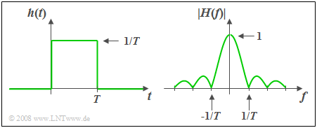
$\text{Example 1:}$ The impulse response $h(t)$ of the so-called slit–low-pass filter is constant over a time interval $T$ and is zero outside this time interval.
- The associated amplitude response as the magnitude of the frequency response is
- $$\vert H(f)\vert = \vert {\rm si}(\pi fT)\vert .$$
- The area over $h(t)$ is equal to $H(f = 0) = 1$. It follows that:
In the range $ 0 < t < T$ the impulse response must be equal to $1/T$ . - The phase response is given by
- $$b(f) = \left\{ \begin{array}{l} \hspace{0.25cm}\pi/T \\ - \pi/T \\ \end{array} \right.\quad \quad\begin{array}{*{20}c} \text{für} \\ \text{für} \\ \end{array}\begin{array}{*{20}c}{\left \vert \hspace{0.05cm} f\hspace{0.05cm} \right \vert > 0,} \\{\vert \hspace{0.05cm} f \hspace{0.05cm} \vert < 0.} \\\end{array}$$
- For $h(t)$ that are symmetric about $t = 0$ (i.e. noncausal) $b(f)=0$ holds.
Some Laws of the Fourier Transformation
The Gesetzmäßigkeiten der Fouriertransformation have already been explained in detail in the book ”Signal Representation”.
The following is a short summary, where $H(f)$ describes the frequency response of an LTI-system and whose inverse Fourier transform $h(t)$ is the impulse response. The laws and principles are applied more frequently in the exercises for this chapter ”System-theoretical Foundations”.
Here, we also refer to the didactic video Gesetzmäßigkeiten der Fouriertransformation.
In the following equations the short symbol of the Fourier transformation is used. The filled-out circle indicates the spectral domain, the white one the time domain.
- Multiplication by a constant factor:
- $$k \cdot H(f)\bullet\!\!-\!\!\!-\!\!\!-\!\!\circ\,k \cdot h(t).$$
- For $k \lt 1$ one deals with attenuation, while $k \gt 1$ stands for amplification.
- Similarity Theorem:
- $$H({f}/{k})\bullet\!\!-\!\!\!-\!\!\!-\!\!\circ\,|k| \cdot h(k\cdot t).$$
- This implies: Compression $(k < 1)$ of the frequency response results in a wider and lower impulse response.
- Dilation $(k > 1)$ of $H(f)$ makes $h(t)$ narrower and higher.
- Displacement Theorem in the frequency and time domain:
- $$H(f - f_0) \bullet\!\!-\!\!\!-\!\!\!-\!\!\circ\, h( t )\cdot {\rm e}^{\hspace{0.05cm}{\rm j}2\pi f_0 t},\hspace{0.9cm}
H(f) \cdot {\rm e}^{-{\rm j}2\pi ft_0}\bullet\!\!-\!\!\!-\!\!\!-\!\!\circ\, h( t- t_0 ).$$
- A shift by $t_0$ (transit time) thus leads to multiplication by a complex exponential function in the frequency domain.
- Thereby, the amplitude response $|H(f)|$ does not change .
- Differentiation Theorem in the frequency and time domain:
- $$\frac{1}{{{\rm j}2\pi }} \cdot \frac{{{\rm d}H( f )}}{{{\rm d}f}} \bullet\!\!-\!\!\!-\!\!\!-\!\!\circ\,- t \cdot h( t ),\hspace{0.9cm} {\rm j}\cdot 2\pi f \cdot H( f ){}\bullet\!\!-\!\!\!-\!\!\!-\!\!\circ\, \frac{{{\rm d}h( t )}}{{\rm d}t}.$$
- A differentiating element in the LTI-system leads to a multiplication by ${\rm j}\cdot 2πf$ in the frequency domain and thus among other things to a phase rotation by $90^{\circ}$.
Causal Systems
$\text{Definition:}$ An LTI-system is said to be causal if the impulse response $h(t)$ – that is the inverse Fourier transform of the frequency response $H(f)$ – satisfies the following condition:
- $$h(t) = 0 \hspace{0.25cm}{\rm f\ddot{u}r}\hspace{0.25cm} t < 0.$$
$\text{Please note:}$ Any realisable system is causal.
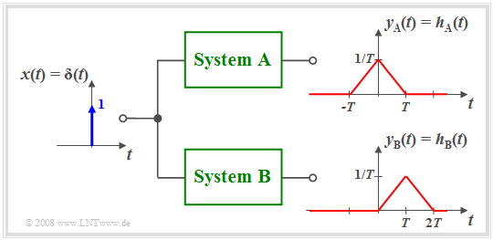
$\text{Example 2:}$ The diagram illustrates the difference between the noncausal system $\rm A$ and the causal system $\rm B$.
- In system $\rm A$ the effect starts earlier $($at $t =\hspace{0.05cm} –T)$ than the cause $($Dirac delta function at $t = 0)$, which of course is not possible in practice.
- Almost all noncausal systems can be transformed into a feasible causal system using a runtime $\tau$ .
- For example, with $\tau = T$ the following holds:
- $$h_{\rm B}(t) = h_{\rm A}(t - T).$$
- All statements made so far apply for causal as well as noncausal systems.
- However, for the description of causal systems some specific properties can be used as explained in the third main chapter ”Description of Causal Realisable Systems” of this book .
In this first and the following second main chapter we mainly consider noncausal systems since their mathematical description is usually simpler.
- So, the frequency response $H_{\rm A}(f)$ real,
- while for $H_{\rm B}(f)$ the additional term ${\rm e}^{–{\rm j2π}f\hspace{0.05cm}T}$ has to be considered.
Computation of the Output Signal
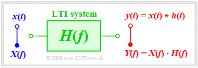
We consider the following problem: Let the input signal $x(t)$ and the frequency response $H(f)$ be known. The output signal $y(t)$ is to be determinded.
If the solution is to be determined in the frequency domain, first the spectrum $X(f)$ must be determined from the given input signal $x(t)$ via Fouriertransformation and multiplied by the frequency response $H(f)$ . By a Fourierrücktransformation of the product the signal $y(t)$ is obtained.
Here is a summary of the entire solution process:
- $${\rm 1.\,\, step\hspace{-0.1cm} :}\hspace{0.5cm} X(f)\bullet\!\!-\!\!\!-\!\!\!-\!\!\circ\, x( t )\hspace{1.55cm}{\rm input\:spectrum},$$
- $${\rm 2.\,\, step\hspace{-0.1cm}:}\hspace{0.5cm}Y(f)= X(f) \cdot H(f) \hspace{0.82cm}{\rm output\:spectrum},$$
- $${\rm 3.\,\, step\hspace{-0.1cm}:}\hspace{0.5cm} y(t)\circ\!\!-\!\!\!-\!\!\!-\!\!\bullet\, Y(f )\hspace{1.55cm}{\rm output\:signal}.$$
The same result is obtained after the computation in the time domain by first determining the impulse response $h(t)$ from the frequency response $H(f)$ by means of inverse Forier transformation and then applying the convolution operation:
- $$y(t) = x (t) * h (t) = \int_{ - \infty }^{ + \infty } {x ( \tau )} \cdot h ( {t - \tau } ) \hspace{0.1cm}{\rm d}\tau.$$
- The results are identical for both approaches.
- Purposefully, the procedure of solution with less computational effort should be chosen.
$\text{Example 3:}$ At the input of a slit-low-pass filter with rectangular impulse response of width $T$ (see $\text{Example 1}$) a rectangular pulse $x(t)$ of duration $2T$ is applied.
In this case, direct computation in the time domain is more convenient:
- The convolution of two rectangles $x(t)$ and $h(t)$ of different widhts results in a trapezoidal output signal $y(t)$.
- The low-pass property of the filter can be seen from the finite edge steepness of $y(t)$.
- The pulse height $3\text{ V}$ is preserved in this example because of
- $$H(f = 0) = 1/T · T = 1.$$
Step Response
$\text{Definition:}$ In practice, one of the often used input functions $x(t)$ in order to measure $H(f)$ is the step function
- $${\rm \gamma}(t) = \left\{ \begin{array}{l} \hspace{0.25cm}0 \\ 0.5 \\ \hspace{0.25cm} 1 \\ \end{array} \right.\quad \quad\begin{array}{*{20}c} \text{for} \\ \text{for}\\ \text{for} \\ \end{array}\begin{array}{*{20}c}{\vert \hspace{0.05cm} t\hspace{0.05cm} \vert < 0,} \\ {\vert \hspace{0.05cm}t\hspace{0.05cm} \vert = 0,} \\ {\vert \hspace{0.05cm} t \hspace{0.05cm} \vert > 0.} \\ \end{array}$$
The step response $\sigma(t)$ is the response of the system if the step function $\gamma(t)$ is applied to the input:
- $$x(t) = {\rm \gamma}(t)\hspace{0.5cm}\Rightarrow \hspace{0.5cm} y(t) = {\rm \sigma}(t).$$
The computation in the frequency domain would be a bit laborious here because the following equation would have to be applied:
- $${\rm \sigma}(t)\circ\!\!-\!\!\!-\!\!\!-\!\!\bullet\, X(f ) \cdot H(f) =\left({1}/{2}\cdot \delta(f) + \frac{1}{{\rm j}\cdot 2\pi f} \right) \cdot H(f).$$
In contrast to this, the computation in the time domain leads directly to the result:
- $${\rm \sigma}(t) = \int_{ - \infty }^{ t } {h ( \tau )} \hspace{0.1cm}{\rm d}\tau.$$
For causal sytems $h(\tau) = 0$ holds for $\tau \lt 0$, such that the lower limit of integration in the above equation can be set to $\tau = 0$ .
$\text{Proof:}$ The above result is also insightful for the following reason:
- The step function $\gamma(t)$ is related to the Dirac delta function $\delta(t)$ as follows:
- $${\rm \gamma}(t) = \int_{ - \infty }^{ t } {\delta ( \tau )} \hspace{0.1cm}{\rm d}\tau.$$
- Since we have assumed linearity and integration is a linear operation the corresponding relationship also applies to the output signal:
- $${\rm \sigma}(t) = \int_{ - \infty }^{ t } {h ( \tau )} \hspace{0.1cm}{\rm d}\tau.$$
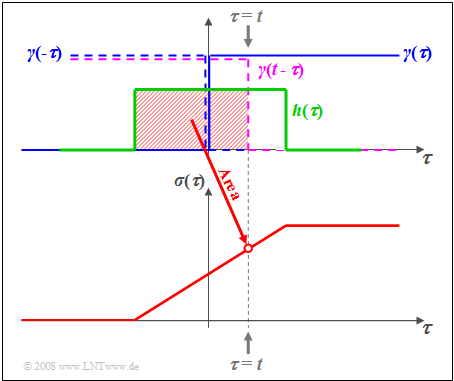
$\text{Example 4:}$ The graph illustrates the facts for the rectangular impulse response $h(\tau)$.
- The abscissa has been renamed to $\tau$ .
- The step function $\gamma(\tau)$ is drawn in blue.
- $\gamma(t - \tau)$ is obtained by mirroring and shifting ⇒ curve dashed in violet.
- The red shaded area thus gives the step response $\sigma(\tau)$ at time $\tau = t$ .
Exercises for the Chapter
Aufgabe 1.3: Gemessene Sprungantwort
Aufgabe 1.3Z: Exponentiell abfallende Impulsantwort
Aufgabe 1.4: Zum Tiefpass 2. Ordnung
Aufgabe 1.4Z: Alles rechteckförmig


