Exercise 1.2: Distortions? Or no Distortion?
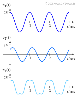
The communication systems $S_1$, $S_2$ and $S_3$ analyzed in terms of the distortions they cause. For this purpose, the cosine-shaped test signal with signal frequency $f_{\rm N} = 1\text{ kHz}$ is applied to the input of each system:
- $$q(t) = 2 \;{\rm V} \cdot \cos(2 \pi f_{\rm N} t )$$
The three signals at the system output are measured, as shown in the graph:
- $$v_1(t) = 2 \;{\rm V} \cdot \cos(2 \pi f_{\rm N} t )\hspace{0.05cm},$$
- $$v_2(t) = 1 \;{\rm V} \cdot \cos(2 \pi f_{\rm N} t + 1 \;{\rm V} \cdot \sin(2 \pi f_{\rm N} t) \hspace{0.05cm},$$
- $$v_3(t)= 1.5 \;{\rm V} \cdot \cos(2 \pi f_{\rm N} t) - 0.3 \;{\rm V} \cdot \cos(6 \pi f_{\rm N} t)\hspace{0.05cm}.$$
The noise components that are always present in practice will be assumed to be negligible here.
Hints:
- This exercise belongs to the chapter Quality criteria. Particular reference is made to the page Signal-to-noise power ratio and to the chapter Non-linear distortions in the book "Linear and Time-Invariant Systems".
- For nonlinear distortion, the sink SNR is $ρ_v = 1/K^2$, , where the distortion factor $K$ is the ratio of the rms values of all harmonics to the rms value of the fundamental frequency.
Questions
Solution
- System $S_1$ could well be an ideal system, namely if for all frequencies $f_{\rm N}$ the condition $v(t) = q(t)$ were satisfied.
- The second alternative is also possible, since the ideal system is a special case of distortion-free systems.
- However, if at a different message frequency $f_{\rm N} \ne 1$ kHz the condition $v(t) = q(t)$ were not satisfied, then a linearly distorting system would exist whose frequency response would happen to be equal to $1$ at frequency $f_{\rm N}$ .
- In contrast, a nonlinearly distorting system (Answer 4) can be excluded due to the lack of harmonics.
(2) Entsprechend den Ausführungen im Kapitel „Harmonische Schwingung” im Buch „Signaldarstellung” gelten folgende Gleichungen:
- $$A \cdot \cos(\omega_{\rm N} t ) + B \cdot \sin(\omega_{\rm N} t ) = C \cdot \cos(\omega_{\rm N} t - \varphi)\hspace{0.3cm} \Rightarrow \hspace{0.3cm} C = \sqrt{A^2 + B^2},\hspace{0.5cm}\varphi ={\rm arctan}\hspace{0.1cm} ({A}/{B})\hspace{0.05cm}$$
- Angewandt auf das vorliegende Beispiel erhält man
- $$C = \sqrt{(1 \,{\rm V})^2 + (1 \,{\rm V})^2}= 1.414\,{\rm V}\hspace{0.05cm}.$$
- Der Dämpfungsfaktor des Systems hat somit den Wert $α = 1.414/2 \hspace{0.15cm}\underline{= 0.707}$, und für die Phase gilt:
- $$ \varphi ={\rm arctan}\hspace{0.1cm}\frac {1 \,{\rm V}}{1 \,{\rm V}} = 45^{\circ} = {\pi}/{4}\hspace{0.05cm}.$$
- Die Umformung $\cos(\omega_{\rm N} t - \varphi)= \cos[\omega_{\rm N} (t - \tau)]$ erlaubt Aussagen über die Laufzeit:
- $$\tau =\frac {\varphi}{2\pi f_{\rm N}} = \frac {\pi /4}{2\pi f_{\rm N}} = \frac {1}{8 \cdot 1 \,{\rm kHz}} \hspace{0.15cm}\underline {= 125\,{\rm µ s}}\hspace{0.05cm}.$$
(3) Richtig sind die Lösungsvorschläge 2 und 3:
- Das System $S_2$ ist nach den Ausführungen zur Teilaufgabe (1) weder ideal noch nichtlinear verzerrend.
- Dagegen sind die Alternativen 2 und 3 möglich, je nachdem, ob die berechneten Werte von $α$ und $τ$ für alle Frequenzen erhalten bleiben oder nicht.
- Mit einer einzigen Messung bei nur einer Frequenz kann allerdings diese Frage nicht geklärt werden.
(4) Das Signal $v_3(t)$ beinhaltet eine Oberwelle dritter Ordnung. Deshalb ist die Verzerrung nichtlinear ⇒ Lösungsvorschlag 2.
(5) Mit den Amplituden $A_1 = 1.5 \ \rm V$ und $A_3 = -0.3\ \rm V$ erhält man für den Klirrfaktor:
- $$ K_3 =\frac {|A_3|}{|A_1|} = 0.2\hspace{0.05cm}.$$
- Deshalb beträgt das Sinken–SNR entsprechend der angegebenen Gleichung $ρ_{v3} = 1/K_3^{ 2 } = 25$.
Zum gleichen Ergebnis kommt man nach der allgemeinen Berechnung.
- Aus den Amplituden von Quellensignal und Grundwelle des Sinkensignals erhält man für den frequenzunabhängigen Dämpfungsfaktor:
- $$ \alpha =\frac {1.5 \,{\rm V}}{2 \,{\rm V}} = 0.75\hspace{0.05cm}.$$
- Das von den nichtlinearen Verzerrungen herrührende Fehlersignal lautet deshalb:
- $$\varepsilon_3(t) = v_3(t) - \alpha \cdot q(t) = - 0.3 \,{\rm V} \cdot \cos(6 \pi f_{\rm N} t)\hspace{0.05cm}.$$
- Damit ergibt sich die Verzerrungsleistung:
- $$P_{\varepsilon 3}= {1}/{2} \cdot (0.3 \,{\rm V})^2 = 0.045 \,{\rm V}^2\hspace{0.05cm}.$$
- Mit der Leistung des Quellensignals,
- $$P_{q}= {1}/{2} \cdot (2\,{\rm V})^2 = 2 \,{\rm V}^2\hspace{0.05cm},$$
- erhält man unter Berücksichtigung des gerade berechneten Dämpfungsfaktors $ \alpha = 0.75 $:
- $$\rho_{v3} = \frac{\alpha^2 \cdot P_{q}}{P_{\varepsilon 3}} = \frac{0.75^2 \cdot 2 {\rm V}^2}{0.045 } \hspace{0.15cm}\underline {= 25}\hspace{0.05cm}.$$
