Exercise 1.3Z: Thermal Noise
A fundamental disturbance and one that occurs in any communication system is thermal noise , since any resistance $R$ with an absolute temperature of $θ$ (in "degrees Kelvin") produces a noise signal $n(t)$ with a (one-sided) noise power density
- $${N_{\rm 0, \hspace{0.05cm}min}}= k_{\rm B} \cdot \theta \hspace{0.3cm}\left(k_{\rm B} = 1.38 \cdot 10^{-23} \hspace{0.05cm}{\rm Ws}/{\rm K}\right)$$
$k_{\rm B}$ denotes the Boltzmann constant (from German "Konstante").
However, this is limited to $6\text{ THz}$ for physical reasons. Furthermore, it can be observed that this minimum value can only be achieved with exact impedance matching.
In the realization of a circuit unit - for example, an amplifier - the effective noise power density is usually significantly greater, since several noise sources add up, and mismatches also play a role. This effect is captured by the noise value $F \ge 1$ . It holds that:
- $$N_0 = F \cdot {N_{\rm 0, \hspace{0.05cm}min}}= F \cdot k_{\rm B} \cdot \theta \hspace{0.05cm}.$$
With a bandwidth $B$, the effective noise power is characterized by:
- $$N = N_0 \cdot B \hspace{0.1cm}\left(= N_0 \cdot B\cdot R = \sigma_n^2\right) \hspace{0.01cm}.$$
- According to the first equation, the result is the actual, physical power in "watts" $\rm (W)$.
- According to the second equation, given in brackets, the result has the unit „$\rm V^{ 2 }$”.
- This means that the power is here converted to the reference resistance $R = 1\ Ω$ – as is often the case in communications engineering.
- This equation must also be used to calculate the rms value (the dispersion) $σ_n$ of the noise signal $n(t)$ .
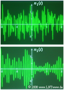
All equations apply regardless of whether the noise is low-pass or band-pass. The graph shows two noise signals $n_1(t)$ and $n_2(t)$ of equal bandwidth. Question (4) asks which of these signals will appear at the output of a lowpass and a bandpass, respectively.
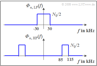
The two-sided noise power density of band-limited lowpass noise $n_{\rm TP}(t)$ is:
- $$ {\it \Phi}_{n, {\hspace{0.05cm}\rm TP}}(f) = \left\{ \begin{array}{c} N_0/2 \\ 0 \\ \end{array} \right. \begin{array}{*{10}c} {\rm{f\ddot{u}r}} \\ \\ \end{array}\begin{array}{*{20}c} {\left| \hspace{0.005cm} f\hspace{0.05cm} \right| < B,} \\ {\rm sonst.} \\ \end{array}$$
Dagegen gilt bei bandpassartigem Rauschen $n_{\rm BP}(t)$ mit der Mittenfrequenz $f_{\rm M}$:
- $${\it \Phi}_{n, {\hspace{0.05cm}\rm BP}}(f) = \left\{ \begin{array}{c} N_0/2 \\ 0 \\ \end{array} \right. \begin{array}{*{10}c} {\rm{f\ddot{u}r}} \\ \\ \end{array}\begin{array}{*{20}c} {\left| \hspace{0.005cm} f - f_{\rm M}\hspace{0.05cm} \right| < B/2,} \\ {\rm sonst.} \\ \end{array}.$$
Für alle nachfolgenden numerischen Berechnungen wird vorausgesetzt:
- $$ F = 10, \hspace{0.2cm}\theta = 290\,{\rm K},\hspace{0.2cm}R = 50\,{\rm \Omega},\hspace{0.2cm}B = 30\,{\rm kHz},\hspace{0.2cm}f_{\rm M} = 0 \hspace{0.1cm}{\rm bzw.}\hspace{0.1cm}100\,{\rm kHz}\hspace{0.05cm}.$$
Hinweise:
- Die Aufgabe gehört zum Kapitel Qualitätskriterien.
- Bezug genommen wird insbesondere auf die Seite Einige Anmerkungen zum AWGN–Kanalmodel.
- Durch die Angabe der Leistungen in $\rm W$att sind diese unabhängig vom Bezugswiderstand $R$, während die Leistung mit der Einheit $\rm V^2$ nur für $R = 1\ \Omega$ direkt ausgewertet werden kann.
Fragebogen
Musterlösung
- $$N_0 = F \cdot k_{\rm B} \cdot \theta = 10 \cdot 1.38\hspace{0.05cm}\cdot 10^{-23} \hspace{0.05cm}\frac{\rm Ws}{\rm K}\cdot 290\,{\rm K} \hspace{0.15cm}\underline {\approx 4\hspace{0.05cm}\cdot 10^{-20} \hspace{0.05cm}{\rm W}/{\rm Hz}}\hspace{0.05cm}.$$
(2) Die angegebene Rauschleistungsdichte $N_0$ ist physikalisch auf $6$ THz begrenzt. Damit beträgt die maximale Rauschleistung:
- $$N_{\rm max} = 4\hspace{0.05cm}\cdot 10^{-20} \hspace{0.08cm}\frac{\rm W}{\rm Hz}\cdot 6 \cdot10^{12} \hspace{0.08cm}{\rm Hz}\hspace{0.15cm}\underline {= 0.24\hspace{0.08cm}\cdot 10^{-6}\;{\rm W}}\hspace{0.05cm}.$$
(3) Nun ergibt sich für die Rauschleistung:
- $$N = N_0 \cdot B = 4\hspace{0.08cm}\cdot 10^{-20} \hspace{0.08cm}\frac{\rm W}{\rm Hz}\cdot 3 \cdot10^{4} \hspace{0.08cm}{\rm Hz}\hspace{0.15cm}\underline {= 12\hspace{0.05cm}\cdot 10^{-16}\;{\rm W}}\hspace{0.05cm}.$$
- Umgerechnet auf den Bezugswiderstand $R = 1 \ Ω$:
- $$N = N_0 \cdot B \cdot R = 12\hspace{0.05cm}\cdot 10^{-16}\;{\rm W}\hspace{0.05cm} \cdot 50 \; {\rm \Omega}= 6\hspace{0.05cm}\cdot 10^{-14}\;{\rm V^2}\hspace{0.05cm}.$$
- Der Rauscheffektivwert $σ_n$ ist die Quadratwurzel hieraus:
- $$\sigma_n= \sqrt{6\hspace{0.05cm}\cdot 10^{-14}\;{\rm V^2}} \hspace{0.15cm}\underline {= 0.245 \hspace{0.05cm}\cdot 10^{-6}\;{\rm V}}\hspace{0.05cm}.$$
(4) Richtig ist der Lösungsvorschlag 1:
- Im Zufallssignal $n_2(t)$ erkennt man gewisse Regelmäßigkeiten ähnlich einer harmonischen Schwingung – es ist Bandpass–Rauschen.
- Dagegen handelt es sich beim Signal $n_1(t)$ um Tiefpass–Rauschen.
(5) Die Rauschleistungsdichte des Zufallssignals $n_1(t)$ ist im Frequenzbereich $|f| < 30$ kHz konstant:
- $${\it \Phi}_{n,\hspace{0.05cm}{ \rm TP} }(f) \hspace{-0.05cm}=\hspace{-0.05cm} \frac{N_0}{2} \hspace{0.15cm}\underline {=2\hspace{0.05cm}\hspace{-0.05cm}\cdot \hspace{-0.05cm} 10^{-12} \hspace{0.05cm}{\rm W}/{\rm Hz}}\hspace{0.05cm}.$$
- Dieser Wert gilt somit auch für die Frequenz $f = 20$ kHz.
(6) Wie aus der Grafik hervorgeht, ist ${\it Φ}_{n, \hspace{0.05cm}\rm BP}(f)$ nur im Bereich zwischen $85$ kHz und $115$ kHz ungleich Null, wenn die Bandbreite $B = 30$ kHz beträgt.
- Bei der Frequenz $f = 120$ kHz ist die Rauschleistungsdichte somit Null:
- $${\it Φ}_{n, \hspace{0.05cm}\rm BP}(f = 120 \ \rm kHz)\hspace{0.15cm}\underline{=0}.$$

