Exercise 2.3: DSB-AM Realization
In order to realize the so-called "Double-Sideband Amplitude Modulation $\text{(DSB-AM)}$ with carrier", an amplifier with the following characteristic curve must be used:
- $$y = g(x) = U \cdot \left( 1 -{\rm e} ^{-x/U}\right)$$
- Here, $x = x(t)$ and $y = y(t)$ are time-dependent voltages at the input and output of the amplifier, respectively.
- The parameter $U = 3 \ \rm V$ indicates the saturation voltage of the amplifier.
This curve is driven at the operating point $A_0 = 2\ \rm V$. This is achieved, for example, by the input signal
- $$x(t) = A_0 + z(t) + q(t)\hspace{0.05cm}.$$
Assume cosine oscillations for both the carrier and the source signal:
- $$ z(t) = A_{\rm T} \cdot \cos (2 \pi f_{\rm T} t),\hspace{0.2cm} A_{\rm T} = 1\,{\rm V},\hspace{0.2cm} f_{\rm T} = 30\,{\rm kHz},$$
- $$ q(t) = A_{\rm N} \cdot \cos (2 \pi f_{\rm N} t),\hspace{0.2cm} A_{\rm N} = 1\,{\rm V},\hspace{0.2cm} f_{\rm N} = 3\,{\rm kHz}\hspace{0.05cm}.$$
In solving this problem, use the auxiliary quantity
- $$w(t) = x(t) - A_0 = z(t) + q(t)\hspace{0.05cm}.$$
The nonlinear characteristic curve can be developed according to a "Taylor series" around the operating point:
- $$y(x) = y(A_0) + \frac{1}{1!} \cdot y\hspace{0.08cm}{\rm '}(A_0) \cdot (x - A_0)+ \frac{1}{2!} \cdot y\hspace{0.08cm}''(A_0) \cdot (x - A_0)^2+ \frac{1}{3!} \cdot y\hspace{0.08cm}'''(A_0) \cdot (x - A_0)^3 + \text{ ...}$$
The output signal can then also be represented as depending on the auxiliary quantity $w(t)$ as follows:
- $$y(t) = c_0 + c_1 \cdot w(t) + c_2 \cdot w^2(t)+ c_3 \cdot w^3(t) +\text{ ...}$$
- The DSB–AM signal $s(t)$ is obtained by band-limiting $y(t)$ to the frequency range from $\text{23 kHz}$ to $\text{37 kHz}$.
- That is, all frequencies other than $f_{\rm T}$, $f_{\rm T}±f_{\rm N}$ and $f_{\rm T}±2f_{\rm N}$ are removed by the band-pass.
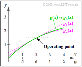
The graphic shows the characteristic curve $g(x)$ and the approximations $g_1(x)$, $g_2(x)$ and $g_3(x)$, when the Taylor series is truncated after the first, second, or third term. It can be seen that the approximation $g_3(x)$ is indistinguishable from $g(x)$ in the range shown.
Hints:
- This exercise belongs to the chapter Double-Sideband Amplitude Modulation.
- Reference will also be made to the chapter Description of nonlinear systems in the book "Linear and Time Invariant Systems".
Questions
Solution
- Thus, the auxiliary quantity $w(t)$ can take values between $w_{\rm min}\hspace{0.15cm}\underline{ = -2 \ \rm V}$ and $w_{\rm max}\hspace{0.15cm}\underline{ = +2 \ \rm V}$.
(2) The coefficient $c_0$ is equal to the characteristic value at the operating point. Using $A_0 = 2 \ \rm V$ and $U = 3 \ \rm V$ we obtain:
- $$c_0 = y(A_0) = U \cdot \left( 1 -{\rm e} ^{-A_0/U}\right) \hspace{0.15cm}\underline {= 1.460\,{\rm V}}\hspace{0.05cm}.$$
- Accordingly, for the Taylor coefficient $c_1$:
- $$c_1 = y\hspace{0.06cm}'(A_0)= {\rm e} ^{-A_0/U}\hspace{0.15cm}\underline { = 0.513}\hspace{0.05cm}.$$
(3) The further derivatives $(n ≥ 2)$ are:
- $$y^{(n)}(A_0)= \frac{(-1)^{n-1}}{U^{n-1}} \cdot {\rm e} ^{-A_0/U} \hspace{0.05cm}.$$
- This results in the following coefficients:
- $$ c_2 = \frac{1}{2!} \cdot y^{(2)}(A_0)= \frac{1}{2U} \cdot {\rm e}^{-A_0/U} \hspace{0.15cm}\underline {= -0.086\,{\rm V^{-1}}}\hspace{0.05cm},$$
- $$c_3 = \frac{1}{3!} \cdot y^{(3)}(A_0)= \frac{1}{6U^2} \cdot {\rm e}^{-A_0/U}\hspace{0.15cm}\underline { = 0.0095\,{\rm V^{-2}}}\hspace{0.05cm}.$$
(4) Setting $c_3 = 0$, the output signal of the amplifier is:
- $$y(t) = c_0 + c_1 \cdot (z(t) + q(t)) + c_2 \cdot (z^2(t) + q^2(t) + 2 \cdot z(t) \cdot q(t))\hspace{0.05cm}.$$
- Thus, after the band-pass, the following signal components remain:
- $$s(t) = c_1 \cdot z(t) + 2 \cdot c_2 \cdot z(t) \cdot q(t) = \left[c_1 \cdot A_{\rm T} + 2 \cdot c_2 \cdot A_{\rm T} \cdot A_{\rm N} \cdot \cos(\omega_{\rm N} t)\right] \cdot \cos(\omega_{\rm T} t)\hspace{0.05cm}.$$
- The modulation depth is then determined as the quotient of the "amplitude of the message oscillation" over the "amplitude of the carrier":
- $$m = \frac{2 \cdot |c_2| \cdot A_{\rm T} \cdot A_{\rm N}}{|c_1| \cdot A_{\rm T}} = \frac{2 \cdot |c_2| \cdot A_{\rm N}}{|c_1| }= \frac{2 \cdot 0.086 \cdot 1\,{\rm V}}{0.513 }\hspace{0.15cm}\underline { = 0.335}\hspace{0.05cm}.$$
(5) Answers 2 and 3 are correct:
- Considering the cubic part, $y(t)$ includes the following other components:
- $$y_3(t) = c_3 \cdot (z(t) + q(t))^3 = c_3 \cdot z^3(t) + 3 \cdot c_3 \cdot z^2(t) \cdot q(t)+ 3 \cdot c_3 \cdot z(t) \cdot q^2(t) + c_3 \cdot q^3(t) \hspace{0.05cm}.$$
- The first term results in components at $f_{\rm T}$ and $3f_{\rm T}$, and the last term results in components at $f_{\rm N}$ and $3f_{\rm N}$.
- The second term gives a component at $f_{\rm N}$ and others at $2f_{\rm T} ± f_{\rm N}$:
- $$3 \cdot c_3 \cdot z^2(t) \cdot q(t)= {3}/{2 } \cdot A_{\rm T}^2 \cdot A_{\rm N} \cdot \left[ \cos(\omega_{\rm N} t) + \cos(2\omega_{\rm T} t) \cdot \cos(\omega_{\rm N} t)\right] \hspace{0.05cm}.$$
- Accordingly, the third summand in the above equation leads to
- $$3 \cdot c_3 \cdot z(t) \cdot q^2(t)= {3}/{2 } \cdot A_{\rm T} \cdot A_{\rm N}^2 \cdot \left[ \cos(\omega_{\rm T} t) + \cos(\omega_{\rm T} t)\cdot \cos(2 \omega_{\rm N} t)\right] \hspace{0.05cm}.$$
- Thus, within the frequency range from $\text{23 kHz}$ to $\text{37 kHz}$, there is indeed a change in the spectral line at $f_{\rm T}$
and new Dirac lines are formed at $f_{\rm T} ± 2f_{\rm N}$, i.e., at $\text{24 kHz}$ and $\text{36 kHz}$. - The resulting distortions are thus nonlinear ⇒ Answer 3 ist correct and Answer 4 is wrong.
