Exercise 2.5Z: Linear Distortions with DSB-AM
As in Exercise 2.5 here we will also examine:
- the DSB–AM/synchronous demodulator combination
- considerations involving a linear distorting channel.
Let the source signal $q(t)$ be a cosine signal with amplitude $A_{\rm N}$ and frequency $f_{\rm N}$, such that the spectrum of the modulated signal is as follows:
- $$S(f)= \frac{A_{\rm N}}{4} \cdot \big[\delta(f + f_{\rm O}) + \delta(f + f_{\rm U}) + \delta(f - f_{\rm U}) + \delta(f - f_{\rm O}) \big]\hspace{0.05cm}.$$
The abbreviations stand for $f_{\rm O} = f_{\rm T} + f_{\rm N}$ (O for German "Oberes Seitenband" i.e. Upper Sideband) and $f_{\rm U} = f_{\rm T} - f_{\rm N}$ (U for "Unteres Seitenband" i.e. Lower Sideband).
The channel frequency response is only given for these two frequencies and is:
- $$ H_{\rm K}(f_{\rm O}) = R_{\rm O} + {\rm j} \cdot I_{\rm O},\hspace{0.2cm}H_{\rm K}(f_{\rm U}) = R_{\rm U} + {\rm j} \cdot I_{\rm U} \hspace{0.05cm}.$$
For negative frequencies, $H_{\rm K}(– f) = H_{\rm K}^*(f)$ always holds.
Use the following values for numerical calculations :
- $$A_{\rm N} = 2\,{\rm V}, \hspace{0.15cm}f_{\rm N} = 3\,{\rm kHz}, \hspace{0.15cm}f_{\rm T} = 30\,{\rm kHz} \hspace{0.05cm},$$
- $$R_{\rm U} = 0.8, \hspace{0.15cm}I_{\rm U} = -0.2, \hspace{0.15cm}R_{\rm O} = 0.4, \hspace{0.15cm}I_{\rm O} = -0.2 \hspace{0.05cm}.$$
In subtask (3) the solution should be found from the resulting frequency response of modulator, channel and demodulator:
- $$H_{\rm MKD}(f) = {1}/{2} \cdot \big[ H_{\rm K}(f + f_{\rm T}) + H_{\rm K}(f - f_{\rm T})\big]\hspace{0.05cm}.$$
Finally, in subtask (4) the following channel frequency response is considered (the plot is only valid for positive frequencies):
- $$ H_{\rm K}(f) = H_{\rm(4)}(f) = \frac{1}{1 + 3{\rm j} \cdot ({f}/{f_{\rm T}} - 1)}\hspace{0.05cm}.$$
Hints:
- This exercise belongs to the chapter Synchronous Demodulation.
- Particular reference is made to the page Influence of linear channel distortions.
Questions
Solution
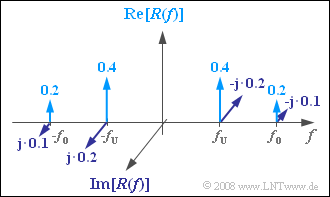
(1) In general, $R(f) = S(f) · H_K(f)$. This gives the line spectrum as shown in the adjacent sketch (all weights still have to be supplemented by the unit "V").
- When the weight of the spectral line is $f = -f_{\rm O}$, then:
- $${\rm Re}[R(-f_{\rm O})]\hspace{0.15cm}\underline{=0.2 \ \rm V},$$
- $${\rm Im}[R(-f_{\rm O})]\hspace{0.15cm}\underline{=0.1 \ \rm V}.$$
(2) The spectral function $V(f)$ of the sink signal $v(t)$ is:
- $$V(f) = \big[ R(f) \star \left[\delta(f - f_{\rm T}) + \delta(f + f_{\rm T}) \right]\big]\cdot H_{\rm E}(f).$$
- According to the laws of the Fourier transform, this can also be written as:
- $$V(f) = \frac{A_{\rm N}}{4} \cdot (R_{\rm O} + {\rm j} \cdot I_{\rm O}) \cdot \delta(f - f_{\rm N}) + \frac{A_{\rm N}}{4} \cdot (R_{\rm U} + {\rm j} \cdot I_{\rm U}) \cdot \delta(f + f_{\rm N})+$$
- $$\hspace{2.25cm}+ \frac{A_{\rm N}}{4} \cdot (R_{\rm O} - {\rm j} \cdot I_{\rm O}) \cdot \delta(f + f_{\rm N})+ \frac{A_{\rm N}}{4} \cdot (R_{\rm U} - {\rm j} \cdot I_{\rm U}) \cdot \delta(f - f_{\rm N}) \hspace{0.05cm}.$$
- All other terms are around twice the carrier frequency and are eliminated by the low-pass filter.
- Rearranging and combining the terms results in:
- $$V(f) = A_{\rm N}\cdot \frac{R_{\rm U} +R_{\rm O}}{2}\cdot \frac{1}{2} \cdot \left[\delta(f - f_{\rm N}) + \delta(f + f_{\rm N}) \right] + A_{\rm N}\cdot \frac{I_{\rm U} - I_{\rm O}}{2}\cdot \frac{\rm j}{2} \cdot \left[-\delta(f - f_{\rm N}) + \delta(f + f_{\rm N}) \right]$$
- $$ \Rightarrow \hspace{0.3cm}v(t) = A_{\rm N}\cdot \frac{R_{\rm U} +R_{\rm O}}{2}\cdot\cos (\omega_{\rm N}\cdot t)+ A_{\rm N}\cdot \frac{I_{\rm U} -I_{\rm O}}{2}\cdot\sin (\omega_{\rm N}\cdot t)\hspace{0.05cm}.$$
- When $R_{\rm U} = 0.8, I_{\rm U} = -0.2, R_{\rm O} = 0.4, I_{\rm O} = -0.2$ it follows:
- $$v(t) = 0.6 \cdot A_{\rm N}\cdot \cos (\omega_{\rm N}\cdot t)\hspace{0.3cm}\Rightarrow \hspace{0.3cm} v(t=0) = 0.6 \cdot A_{\rm N}\hspace{0.15cm}\underline {= 1.2\,{\rm V}}\hspace{0.05cm}.$$
- There is attenuation by a factor of $0.6$ compared to $q(t)$ .
- The synchronous demodulator receives more information about the source signal through the lower sideband than through the upper one.
- Because of the property $I_{\rm O} = I_{\rm U}$ , $v(t)$ is also cosine-shaped.
- Accordingly, either no delay occurs or the delay is an even multiple of the period.
(3) The following equations apply here:
- $$ H_{\rm K}(f_{\rm N}+ f_{\rm T}) = R_{\rm O} + {\rm j} \cdot I_{\rm O} \hspace{0.05cm},\hspace{0.5cm} H_{\rm K}(f_{\rm N}- f_{\rm T}) = H_{\rm K}^{\star}(f_{\rm T}- f_{\rm N}) = R_{\rm U} - {\rm j} \cdot I_{\rm U} $$
- $$\Rightarrow \hspace{0.2cm} H_{\rm MKD}(f_{\rm N}) = {1}/{2} \cdot \big[(R_{\rm O} +R_{\rm U}) + {\rm j} \cdot (I_{\rm O} -I_{\rm U}) \big]\hspace{0.05cm},\hspace{0.2cm} H_{\rm MKD}(-f_{\rm N}) = H_{\rm MKD}^\star(f_{\rm N}) = {1}/{2} \cdot \big[(R_{\rm O} +R_{\rm U}) - {\rm j} \cdot (I_{\rm O} -I_{\rm U}) \big]\hspace{0.05cm}.$$
- Thus, one obtains the same result as in (2), but faster ⇒ Answer 2.
(4) For $f > 0$ the resulting frequency response is:
- $$H_{\rm MKD}(f) = {1}/{2} \cdot \left[ H_{\rm K}(f_{\rm T}+ f) + H_{\rm K}^\star(f_{\rm T}-f)\right]= {1}/{2} \cdot \left[ \frac{1}{1 + 3{\rm j} \cdot (\frac{f_{\rm T}+f}{f_{\rm T}} - 1)} + \frac{1}{1 - 3{\rm j} \cdot (\frac{f_{\rm T}-f}{f_{\rm T}} - 1)}\right] $$
- $$ \Rightarrow \hspace{0.3cm} H_{\rm MKD}(f) = \frac{1}{1 + {\rm j} \cdot {3f}/{f_{\rm T}} } \hspace{0.05cm}.$$
- Inserted at the point where $f = f_{\rm N}$ this leads to the result:
- $$H_{\rm MKD}(f_{\rm N}) = \frac{1}{1 + {\rm j} \cdot {3f_{\rm N}}/{f_{\rm T}} } \hspace{1.0cm} \Rightarrow \hspace{0.3cm}{\rm magnitude} = \frac{1}{\sqrt{1 + ({3f_{\rm N}}/{f_{\rm T}} )^2}} \hspace{0.05cm}, \hspace{0.3cm} {\rm phase} = {\rm arctan}\hspace{0.1cm}({3f_{\rm N}}/{f_{\rm T}}) \hspace{0.05cm}.$$
- When $f_{\rm N}/f_{\rm T} = 0.1$ we get the magnitude $0.958$ and the phase $16.7^\circ$. Thus, the sink signal is:
- $$v(t) = 0.958 \cdot 2\,{\rm V}\cdot \cos (\omega_{\rm N}\cdot t + 16.7^\circ) \hspace{0.3cm} \Rightarrow \hspace{0.3cm} v(t=0)= 1.916\,{\rm V}\cdot \cos ( 16.7^\circ)\hspace{0.15cm}\underline { = 1.835\,{\rm V}}\hspace{0.05cm}.$$

