Contents
# OVERVIEW OF THE SECOND MAIN CHAPTER #
In this chapter, »periodic signals« are considered and described mathematically »in the time and frequency domain«.
This chapter contains in detail:
- Some basic terms like »period duration«, »basic frequency« and »circular frequency«,
- the properties of a »DC signal« as a limiting case of a periodic signal,
- the definition and interpretation of the »Dirac delta function«,
- the »spectral representation« of a DC signal or a DC signal component,
- the time and frequency representation of »harmonic oscillations«, and finally
- the application of »Fourier series« for spectral analysis of periodic signals.
Features and applications
Periodic signals are of great importance for Communications Engineering:
- They belong to the class of »deterministic signals«, whose time function can be specified in analytical form.
- Their signal path is thus known for all times $t$ and can be clearly predicted for the future.
- They are therefore never information-carrying signals.
Nevertheless, periodic signals are often also required in Communications Engineering, for example
- for modulation and demodulation in carrier frequency systems,
- for synchronization and clock regeneration in digital systems,
- as test and verification signals during system implementation.
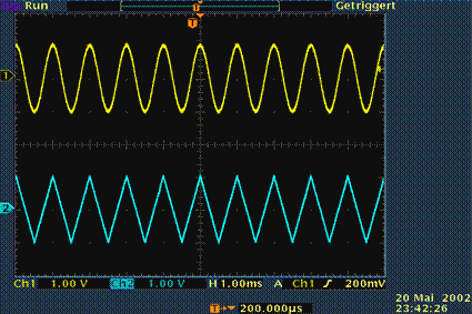
$\text{Example 1:}$ The oscilloscope image shows two typical representatives of periodic signals:
- above a cosine signal,
- below a triangular signal.
As can be seen from the displayed settings, the period duration of both signals is one millisecond and the amplitude one volt.
Definition and parameters
Before we turn to the signal parameters of a periodic signal, the term »periodicity« shall be clearly defined:
$\text{Definition:}$ A »periodic signal« $x(t)$ is present if for all arbitrary values of $t$ and all integer values of $i$ with an appropriate $T_{0}$ applies:
- $$x(t+i\cdot T_{0}) = x(t).$$
This results in the following parameters:
- The »period duration« $T_{0}$ indicates the smallest possible value, which satisfies the above equation.
- The »basic frequency« $f_{0} = 1/T_{0}$ describes the number of periods per time unit $($mostly per second$)$.
- The unit "1/s" is also called "Hz", named after the German physicist $\text{Heinrich Hertz}$.
- The »basic circular frequency« $\omega_{0}$ represents the angular rotation per second, usually given in radians.
- In contrast to the basic frequency, the unit "Hz" is not common here, but "1/s". The following equation applies:
- $$\omega_{0}=2\pi f_{0} = {2\pi}/{T_{0}}.$$
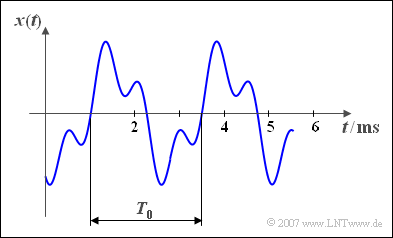
$\text{Example 2:}$ Here, a periodic time signal is shown:
- The period duration is $T_{0} = 2.5 \ \rm ms$.
- From this the basic frequency $f_0 = 400 \ \rm Hz$ is calculated.
- The basic circular frequency results to $\omega_{0}=2513 \ \rm 1/s.$
Resulting period duration
If a signal $x(t)$ consists of the sum of two periodic signals $x_{1}(t)$ and $x_{2}(t)$ with period durations $T_{1}$ or $T_{2}$, the resulting period duration of the sum signal is the smallest common multiple of $T_{1}$ and $T_{2}$.
- This statement applies independently of the amplitude and phase relations.
- On the other hand, if $T_{1}$ and $T_{2}$ don't have a rational common multiple $($Example: $T_{2} = \pi \cdot T_{1})$, then the sum signal $x(t)$ is in contrast to its two components $x_{1}(t)$ and $x_{2}(t)$ not periodic.
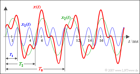
$\text{Example 3:}$ Here, a cosinusoidal signal $x_{1}(t)$ with period duration $T_{1} = 2\; {\rm ms}$ $($blue signal course$)$ is added with a sinusoidal signal $x_{2}(t)$ with period duration $T_{2} = 5\; {\rm ms}$ and twice the amplitude $($green curve).
- The $($red$)$ sum signal $x(t) = x_{1}(t) + x_{2}(t)$ then shows the resulting period duration $T_{0} = 10\; {\rm ms}$ ⇒ basic frequency $f_{0} = 100\; {\rm Hz}$.
- The frequency $f_{0}$ itself is not contained in $x(t)$ only integer multiples of it, namely
- $f_{1} = 500\; {\rm Hz}$ and $f_{2} = 200\; {\rm Hz}$.
⇒ With the interactive applet »Period Duration of Periodic Signals« the resulting period of two harmonic oscillations can be determined.
Exercises for the chapter


