Exercise 2.11: Envelope Demodulation of an SSB Signal
Let us consider the transmission of the cosine signal
- $$ q(t) = A_{\rm N} \cdot \cos(\omega_{\rm N} \cdot t)$$
according to the modulation method "USB–AM with carrier". At the receiver, the high frequency is reset to the LF range with an envelope demodulator .
The channel is assumed to be ideal such that the received signal $r(t)$ is identical to the transmit signal $s(t)$ . With a sideband-to-carrier ratio
- $$ \mu = \frac{A_{\rm N}}{2 \cdot A_{\rm T}}$$
the equivalent lowpass signal can be written as:
- $$r_{\rm TP}(t) = A_{\rm T} \cdot \left( 1 + \mu \cdot {\rm e}^{{\rm j} \hspace{0.03cm}\cdot \hspace{0.03cm}\omega_{\rm N}\cdot \hspace{0.03cm}\hspace{0.03cm}t} \right) \hspace{0.05cm}$$
The envelope – i.e., the magnitude of this complex signal – can be determined by geometric considerations. Independent of the parameter $μ$, one obtains:
- $$a(t ) = A_{\rm T} \cdot \sqrt{1+ \mu^2 + 2 \mu \cdot \cos(\omega_{\rm N} \cdot t)}\hspace{0.05cm}.$$
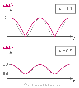
The time-independent envelope $a(t)$ for $μ = 1$ and $μ = 0.5$ is shown in the graph. In each case, the amplitude-matched cosine oscillations, which would be a prerequisite for distortion-free demodulation, are plotted as dashed comparison curves.
- The periodic signal $a(t)$ can be approximated by a Fourier Series :
- $$a(t ) = A_{\rm 0} + A_{\rm 1} \cdot \cos(\omega_{\rm N} \cdot t) + A_{\rm 2} \cdot \cos(2\omega_{\rm N} \cdot t)+ A_{\rm 3} \cdot \cos(3\omega_{\rm N} \cdot t)\hspace{0.05cm}+\text{...}$$
- The Fourier coefficients were determined using a simulation program. With $μ = 1$ the following values were obtained:
- $$A_{\rm 0} = 1.273\,{\rm V},\hspace{0.3cm} A_{\rm 1} = 0.849\,{\rm V},\hspace{0.3cm}A_{\rm 2} = -0.170\,{\rm V},\hspace{0.3cm} A_{\rm 3} = 0.073\,{\rm V},\hspace{0.3cm}A_{\rm 4} = 0.040\,{\rm V} \hspace{0.05cm}.$$
- Accordingly, for $μ = 0.5$, the simulation yielded:
- $$A_{\rm 0} = 1.064\,{\rm V},\hspace{0.3cm} A_{\rm 1} = 0.484\,{\rm V},\hspace{0.3cm}A_{\rm 2} = 0.058\,{\rm V} \hspace{0.05cm}.$$
- The values not given here can be ignored when calculating of the distortion factor.
- The sink signal $v(t)$ is obtained from $a(t)$ as follows:
- $$v(t) = 2 \cdot \big [a(t ) - A_{\rm 0} \big ] \hspace{0.05cm}.$$
- The factor of $2$ corrects for the amplitude loss due to SSB-AM, while the subtraction of the DC signal coefficient $A_0$ takes into account the influence of the high-pass within the envelope demodulator.
In questions (1) to (3) , it is assumed that $A_{\rm N} = 2 \ \rm V$, $A_{\rm T} = 1 \ \rm V$ ⇒ $μ = 1$ , whereas from question (4) , $A_{\rm N} = A_{\rm T} = 1 \ \rm V$ should apply for the parameter $μ = 0.5$.
Hints:
- This exercise belongs to the chapter Single-Sideband Modulation.
- Particular reference is made to the page Sideband-to-carrier ratio.
- Also compare your results to the rule of thumb which states that for the envelope demodulation of an SSB-AM signal with sideband-to-carrier ratio $μ$ , the distortion factor is $K ≈ μ/4$ .
Questions
Musterlösung
- $$ a_{\rm max} = A_{\rm T} \cdot \sqrt{1+ \mu^2 + 2 \mu}= A_{\rm T} \cdot (1+ \mu) = 2\,{\rm V} \hspace{0.05cm},$$
- $$a_{\rm min} = A_{\rm T} \cdot \sqrt{1+ \mu^2 - 2 \mu}= A_{\rm T} \cdot (1- \mu) = 0 \hspace{0.05cm}.$$
- Für die beiden Extremwerte des Sinkensignals folgt daraus:
- $$ v_{\rm max} = 2 \cdot [a_{\rm max} - A_{\rm 0}] = 2 \cdot [2\,{\rm V} - 1.273\,{\rm V}] \hspace{0.15cm}\underline {=1.454\,{\rm V}}\hspace{0.05cm},$$
- $$ v_{\rm min} = -2 \cdot A_{\rm 0} \hspace{0.15cm}\underline {= -2.546\,{\rm V}}\hspace{0.05cm}.$$
(2) Unter Vernachlässigung der Fourierkoeffizienten $A_5$, $A_6$, usw. erhält man:
- $$K = \frac{\sqrt{A_2^2 + A_3^2+ A_4^2 }}{A_1}= \frac{\sqrt{0.170^2 + 0.073^2 + 0.040^2 }{\,\rm V}}{0.849\,{\rm V}}\hspace{0.15cm}\underline { \approx 22.3 \%}.$$
- Die Näherung $K ≈ μ/4$ liefert hier den Wert $25\%$.
(3) Nur der erste Lösungsvorschlag ist richtig.
- Aufgrund des Hochpasses innerhalb des Hüllkurvendemodulators wäre der Gleichsignalanteil auch dann Null, wenn keine Verzerrungen vorlägen.
(4) Analog zur Teilaufgabe (1) gilt hier:
- $$v_{\rm max} = 2 \cdot [a_{\rm max} - A_{\rm 0}] = 2 \cdot [1.5\,{\rm V} - 1.064\,{\rm V}] \hspace{0.15cm}\underline {= 0.872\,{\rm V}}\hspace{0.05cm},$$
- $$ v_{\rm min} = -2 \cdot A_{\rm 0} \hspace{0.15cm}\underline {= -2.128\,{\rm V}}\hspace{0.05cm}.$$
(5) Bei kleinerem Seitenband–zu–Träger–Verhältnis ergibt sich auch ein kleinerer Klirrfaktor:
- $$K = \frac{0.058{\,\rm V}}{0.484\,{\rm V}}\hspace{0.15cm}\underline { \approx 12 \%}.$$
- Die einfache Näherung $K ≈ μ/4$ ergibt hier $12.5\%$.
- Daraus kann geschlossen werden, dass die angegebene Faustformel bei kleinerem $μ$ genauer ist.
(6) Der Klirrfaktor ist dann am größten, wenn eines der Seitenbänder völlig abgeschnitten wird.
- Da aber der Hüllkurvendemodulator keinerlei Kenntnis davon hat, ob
- eine ESB–AM, oder
- eine durch den Kanal extrem beeinträchtigte ZSB–AM
vorliegt, gibt $K_{\rm max} ≈ μ/4$ gleichzeitig eine obere Schranke für die ZSB–AM an.
- Ein Vergleich der Parameter $m = A_{\rm N}/A_{\rm T}$ und $μ = A_{\rm N}/(2A_{\rm T})$ führt zum Ergebnis:
- $$K_{\rm max} = \frac{\mu}{4} = \frac{m}{8} \hspace{0.15cm}\underline {=6.25 \%}.$$
