Exercise 2.4Z: Low-pass Influence with Synchronous Demodulation
Let us consider the same communication system as in Exercise 2.4. But this time, we will assume perfect frequency and phase synchronization for the synchronous demodulator $\rm (SD)$ .
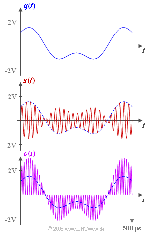
The source signal $q(t)$, the transmission signal $s(t)$ and the signal in the synchronous demodulator before the low-pass filter $b(t)$ are given as follows:
- $$q(t) = q_1(t) + q_2(t)\hspace{0.2cm}{\rm mit }$$
- $$q_1(t) = 2\,{\rm V} \cdot \cos(2 \pi \cdot 2\,{\rm kHz} \cdot t)\hspace{0.05cm},$$
- $$q_2(t) = 1\,{\rm V} \cdot \sin(2 \pi \cdot 5\,{\rm kHz} \cdot t)\hspace{0.05cm},$$
- $$s(t) = q(t) \cdot \sin(2 \pi \cdot 50\,{\rm kHz} \cdot t)\hspace{0.05cm},$$
- $$b(t) = s(t) \cdot 2 \cdot \sin(2 \pi \cdot 50\,{\rm kHz} \cdot t)\hspace{0.05cm}.$$
The graph shows the source signal $q(t)$ at the top and the transmission signal $s(t)$ in the middle.
The sink signal $v(t)$ is shown at the bottom (violet waveform).
- This obviously does not match the source signal (blue dashed curve).
- The reason for this undesired result $v(t) ≠ q(t)$ could be a missing or wrongly dimensioned low-pass filter, for example.
In the subtasks (3) and (4) , a so-called trapezoidal low-pass filter is used, whose frequency response is as follows:
- $$H_{\rm E}(f) = \left\{ \begin{array}{l} \hspace{0.25cm}1 \\ \frac{f_2 -|f|}{f_2 -f_1} \\ \hspace{0.25cm} 0 \\ \end{array} \right.\quad \quad \begin{array}{*{10}c} {\rm{f\ddot{u}r}} \\ {\rm{f\ddot{u}r}} \\ {\rm{f\ddot{u}r}} \\ \end{array}\begin{array}{*{20}c} {\hspace{0.94cm}\left| \hspace{0.005cm} f\hspace{0.05cm} \right| < f_1,} \\ {f_1 \le \left| \hspace{0.005cm}f\hspace{0.05cm} \right| \le f_2,} \\ {\hspace{0.94cm}\left|\hspace{0.005cm} f \hspace{0.05cm} \right| > f_2.} \\ \end{array}$$
Hints:
- This exercise belongs to the chapter Synchronous Demodulation.
- Particular reference is made to the page Block diagram and time domain representation.
- In contrast to Exercise 2.4 , $f_1$ and $f_2$ do not describe signal frequencies, but instead relate to the low-pass filter.
Questions
Solution
- The sink signal shown $v(t)$ stimmt exakt mit dem als Gleichung gegebenen Signal $b(t)$ überein und enthält somit auch Anteile um die doppelte Trägerfrequenz.
- Das Filter $H_{\rm E}(f)$ fehlt entweder ganz oder dessen obere Grenzfrequenz $f_2$ ist zu hoch.
- Bezüglich der unteren Grenzfrequenz $f_1$ ist nur die Aussage möglich, dass diese kleiner ist als die kleinste im Signal $b(t)$ vorkommende Frequenz $\text{(2 kHz)}$.
- Ob ein Gleichanteil durch das Filter entfernt wird oder nicht, ist unklar, da ein solcher im Signal $b(t)$ nicht enthalten ist.
(2) Richtig sind die Aussagen 1 und 3:
- Voraussetzung für eine verzerrungsfreie Demodulation ist, dass bis zu einer bestimmten Frequenz $f_1$ alle Spektralanteile gleich und möglichst ungedämpft übertragen werden und alle Anteile bei Frequenzen $f > f_2$ vollständig unterdrückt werden.
- Der Rechteck– und der Trapeztiefpass erfüllen diese Bedingung.
(3) Sichergestellt werden muss, dass der $\text{5 kHz}$–Anteil noch im Durchlassbereich liegt:
- $$f_{\text{1, min}}\hspace{0.15cm}\underline{ =5 \ \rm kHz}.$$
(4) Alle Spektralanteile in der Umgebung der doppelten Trägerfrequenz – genauer gesagt zwischen $\text{95 kHz}$ und $\text{ 105 kHz}$ – müssen vollständig unterdrückt werden:
- $$f_{\text{2, max}}\hspace{0.15cm}\underline{ =95 \ \rm kHz}.$$
- Ansonsten würde es zu nichtlinearen Verzerrungen kommen.
(5) Richtig ist der Lösungsvorschlag 2:
- Die Grenzfrequenz} $f_{\rm G} = \text{ 4 kHz}$ hätte (lineare) Verzerrungen zur Folge, da dann der $\text{5 kHz}$–Anteil abgeschnitten würde.
- Zu bevorzugen ist der Tiefpass mit der Grenzfrequenz $f_{\rm G} = \text{6 kHz}$, da mit $f_{\rm G} = \text{10 kHz}$ dem Nutzsignal $v(t)$ mehr Rauschanteile überlagert wären.
