Difference between revisions of "Aufgaben:Exercise 3.6: State Transition Diagram"
| Line 1: | Line 1: | ||
| − | {{quiz-Header|Buchseite= | + | {{quiz-Header|Buchseite=Channel_Coding/Code_Description_with_State_and_Trellis_Diagram}} |
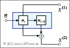
| − | [[File:P_ID2648__KC_A_3_6.png|right|frame| | + | [[File:P_ID2648__KC_A_3_6.png|right|frame|Simple realization of a rate $1/2$ convolutional encoder]] |
| − | + | A description possibility for convolutional coders is provided by the so-called <i>state transition diagram</i>. If the coder $m$ contains memory registers ⇒ influence length $\nu = m + 1$, then there are different states $S_{\mu}$ with $0 ≤ \mu ≤ 2^m -1$, where holds for the index: | |
:$$\mu = \sum_{l = 1}^{m} \hspace{0.1cm}2^{l-1} \cdot u_{i-l} | :$$\mu = \sum_{l = 1}^{m} \hspace{0.1cm}2^{l-1} \cdot u_{i-l} | ||
\hspace{0.05cm}.$$ | \hspace{0.05cm}.$$ | ||
| − | + | This type of code description is to be applied to the convolutional coder of rate $R = 1/2$ outlined above. | |
| Line 15: | Line 15: | ||
| − | + | Hints: | |
| − | * | + | *This exercise belongs to the chapter [[Channel_Coding/Code_Description_with_State_and_Trellis_Diagram| "Code Description with State and Trellis Diagram"]]. |
| − | * | + | *Reference is made in particular to the section [[Channel_Coding/Code_Description_with_State_and_Trellis_Diagram#State_definition_for_a_memory_register|"State definition for a memory register"]]. |
| − | === | + | ===Questions=== |
<quiz display=simple> | <quiz display=simple> | ||
| − | { | + | {How many states does this convolutional encoder have? |
|type="{}"} | |type="{}"} | ||
| − | ${\rm | + | ${\rm Number \ of \ states} \ = \ ${ 2 } |
| − | { | + | {Do you get from any state to all other states? |
|type="()"} | |type="()"} | ||
| − | + | + | + Yes. |
| − | - | + | - No. |
| − | { | + | {What statements hold for the transition from $s_i = S_1$ to $s_{i+1} = S_0$? |
|type="[]"} | |type="[]"} | ||
| − | + | + | + The current information bit must $u_i = 0$ . |
| − | - | + | - The current information bit must be $u_i = 1$ . |
| − | + | + | + The associated code sequence is $\underline{x}_i = (01)$. |
| − | - | + | - The associated code sequence is $\underline{x}_i = (10)$. |
| − | { | + | {What statements hold for the transition from $s_i = S_1$ to $s_{i+1} = S_1$? |
|type="[]"} | |type="[]"} | ||
| − | - | + | - The current information bit must $u_i = 0$ . |
| − | + | + | + The current information bit must be $u_i = 1$ . |
| − | - | + | - The associated code sequence is $\underline{x}_i = (01)$. |
| − | + | + | + The associated code sequence is $\underline{x}_i = (10)$. |
| − | { | + | {Which information sequences are possible? |
|type="[]"} | |type="[]"} | ||
+ $\underline{u} = (1, \, 1, \, 0, \, 0, \, 1 \, 1, \, \text{...}\hspace{0.05cm})$, | + $\underline{u} = (1, \, 1, \, 0, \, 0, \, 1 \, 1, \, \text{...}\hspace{0.05cm})$, | ||
+ $\underline{u} = (1, \, 0, \, 1, \, 0, \, 1, \, 0, \, \text{...}\hspace{0.05cm})$. | + $\underline{u} = (1, \, 0, \, 1, \, 0, \, 1, \, 0, \, \text{...}\hspace{0.05cm})$. | ||
| − | { | + | {Which code sequences are possible? |
|type="[]"} | |type="[]"} | ||
+ $\underline{x} = (11, \, 10, \, 01, \, 00, \, 11, \, 10, \, \text{...}\hspace{0.05cm})$, | + $\underline{x} = (11, \, 10, \, 01, \, 00, \, 11, \, 10, \, \text{...}\hspace{0.05cm})$, | ||
| Line 57: | Line 57: | ||
</quiz> | </quiz> | ||
| − | === | + | ===Solution=== |
{{ML-Kopf}} | {{ML-Kopf}} | ||
| − | [[File:P_ID2649__KC_A_3_6a_neu.png|right|frame| | + | [[File:P_ID2649__KC_A_3_6a_neu.png|right|frame|Equivalent circuit diagram of the encoder under consideration]] |
| − | '''(1)''' | + | '''(1)''' As can be seen from the accompanying equivalent circuit diagram, the encoder contains only one memory element <br>⇒ Memory $m = 1$. Thus there are $2^m \ \underline{= 2}$ states, viz. |
| − | * | + | * the state $S_0 \ \Rightarrow \ u_{i–1} = 0$, |
| − | * | + | * the state $S_1 \ \Rightarrow \ u_{i–1} = 1$. |
| + | '''(2)''' From each state $2^k = 2$ arrows go to different states. | ||
| + | *Since there are only two states, the answer <u>YES</u> is correct. | ||
| − | |||
| − | |||
| − | + | '''(3)''' Correct are the <u>solutions 1 and 3</u>: | |
| − | + | *The information bit $u_i$ present at time $i$ is, with respect to the following time $(j = i + 1)$, the previous bit $(u_{j–1})$. | |
| − | '''(3)''' | + | *Thus $s_{i+1} = u_i$ holds. Only with $u_i = 0$ does one get from $s_i = S_1$ to $s_{i+1} = S_0$ ⇒ <u>Proposed solution 1</u>. |
| − | * | + | *From $s_i = S_1$ ⇒ $u_{i–1} = 1$ follows further ⇒ <u>Proposed solution 3</u>: |
| − | * | ||
| − | * | ||
:$${x}_i^{(1)} = u_i = 0\hspace{0.05cm},\hspace{0.2cm}{x}_i^{(2)} = u_i + u_{i-1}= 0+1 = 1 | :$${x}_i^{(1)} = u_i = 0\hspace{0.05cm},\hspace{0.2cm}{x}_i^{(2)} = u_i + u_{i-1}= 0+1 = 1 | ||
\hspace{0.3cm}\Rightarrow \hspace{0.3cm}\underline{x}_i = (0\hspace{0.05cm},\hspace{0.05cm} 1\hspace{0.05cm}) | \hspace{0.3cm}\Rightarrow \hspace{0.3cm}\underline{x}_i = (0\hspace{0.05cm},\hspace{0.05cm} 1\hspace{0.05cm}) | ||
\hspace{0.05cm}. $$ | \hspace{0.05cm}. $$ | ||
| − | * | + | *The proposed solution 4 could have been ruled out from the beginning. The graph on the specification sheet clearly shows that the coder is systematic: $x_i^{(1)} = u_i$. The combination $u_i = 0$ and $\underline{x}_i = (1, 0)$ would contradict this. |
| − | |||
| − | |||
| − | |||
| − | |||
| − | |||
| − | |||
| − | |||
| + | [[File:P_ID2650__KC_A_3_6d.png|right|frame|State and trellis diagram for the encoder under consideration.]] | ||
| + | '''(4)''' Correct are the <u>solutions 2 and 4</u>: | ||
| + | *Using a similar solution path as in subtask '''(3)''', one arrives at the result that here the current information bit must be $u_i = 1$. | ||
| + | *The corresponding code sequence is $\underline{x}_i = (10)$. | ||
| + | *This results in the following state transition diagram (left) and the trellis diagram that can be derived from it: | ||
| + | *Red arrows indicate the information bit $u_i = 0$, while blue arrows indicate $u_i = 1$. | ||
| − | '''(5)''' <u> | + | '''(5)''' <u>Both proposed solutions</u> are correct. There are no other constraints (except binary) for the information sequences. |
| − | '''(6)''' | + | '''(6)''' Correct is the <u>proposed solution 1</u>. Starting from the state $S_0$ one arrives at. |
| − | * | + | * with $u_1 = 1$ to the state $S_1$, output "$11$", |
| − | * | + | * with $u_2 = 1$ to the state $S_1$, output "$10$", |
| − | * | + | * with $u_3 = 0$ to state $S_0$, output "$01$", |
| − | * | + | * with $u_4 = 0$ to state $S_0$, output "$00$", |
| − | * | + | * with $u_5 = 1$ to state $S_1$, output "$11$", |
| − | * | + | * with $u_6 = 1$ to the state $S_1$, output "$10$". |
| − | + | In contrast, the second code sequence is not possible: | |
| − | * | + | * The output "$11$" means that one started at $S_0$ and comes with $u_1 = 1$ to the state $S_1$. |
| − | * | + | * But in the state $S_1$ then only the outputs "$01$" and "$10$" are possible, but not "$00$". |
{{ML-Fuß}} | {{ML-Fuß}} | ||
Revision as of 14:28, 3 October 2022
A description possibility for convolutional coders is provided by the so-called state transition diagram. If the coder $m$ contains memory registers ⇒ influence length $\nu = m + 1$, then there are different states $S_{\mu}$ with $0 ≤ \mu ≤ 2^m -1$, where holds for the index:
- $$\mu = \sum_{l = 1}^{m} \hspace{0.1cm}2^{l-1} \cdot u_{i-l} \hspace{0.05cm}.$$
This type of code description is to be applied to the convolutional coder of rate $R = 1/2$ outlined above.
Hints:
- This exercise belongs to the chapter "Code Description with State and Trellis Diagram".
- Reference is made in particular to the section "State definition for a memory register".
Questions
Solution
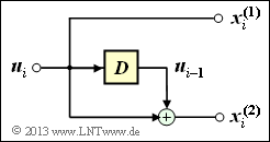
(1) As can be seen from the accompanying equivalent circuit diagram, the encoder contains only one memory element
⇒ Memory $m = 1$. Thus there are $2^m \ \underline{= 2}$ states, viz.
- the state $S_0 \ \Rightarrow \ u_{i–1} = 0$,
- the state $S_1 \ \Rightarrow \ u_{i–1} = 1$.
(2) From each state $2^k = 2$ arrows go to different states.
- Since there are only two states, the answer YES is correct.
(3) Correct are the solutions 1 and 3:
- The information bit $u_i$ present at time $i$ is, with respect to the following time $(j = i + 1)$, the previous bit $(u_{j–1})$.
- Thus $s_{i+1} = u_i$ holds. Only with $u_i = 0$ does one get from $s_i = S_1$ to $s_{i+1} = S_0$ ⇒ Proposed solution 1.
- From $s_i = S_1$ ⇒ $u_{i–1} = 1$ follows further ⇒ Proposed solution 3:
- $${x}_i^{(1)} = u_i = 0\hspace{0.05cm},\hspace{0.2cm}{x}_i^{(2)} = u_i + u_{i-1}= 0+1 = 1 \hspace{0.3cm}\Rightarrow \hspace{0.3cm}\underline{x}_i = (0\hspace{0.05cm},\hspace{0.05cm} 1\hspace{0.05cm}) \hspace{0.05cm}. $$
- The proposed solution 4 could have been ruled out from the beginning. The graph on the specification sheet clearly shows that the coder is systematic: $x_i^{(1)} = u_i$. The combination $u_i = 0$ and $\underline{x}_i = (1, 0)$ would contradict this.
(4) Correct are the solutions 2 and 4:
- Using a similar solution path as in subtask (3), one arrives at the result that here the current information bit must be $u_i = 1$.
- The corresponding code sequence is $\underline{x}_i = (10)$.
- This results in the following state transition diagram (left) and the trellis diagram that can be derived from it:
- Red arrows indicate the information bit $u_i = 0$, while blue arrows indicate $u_i = 1$.
(5) Both proposed solutions are correct. There are no other constraints (except binary) for the information sequences.
(6) Correct is the proposed solution 1. Starting from the state $S_0$ one arrives at.
- with $u_1 = 1$ to the state $S_1$, output "$11$",
- with $u_2 = 1$ to the state $S_1$, output "$10$",
- with $u_3 = 0$ to state $S_0$, output "$01$",
- with $u_4 = 0$ to state $S_0$, output "$00$",
- with $u_5 = 1$ to state $S_1$, output "$11$",
- with $u_6 = 1$ to the state $S_1$, output "$10$".
In contrast, the second code sequence is not possible:
- The output "$11$" means that one started at $S_0$ and comes with $u_1 = 1$ to the state $S_1$.
- But in the state $S_1$ then only the outputs "$01$" and "$10$" are possible, but not "$00$".


