Contents
The different generations of the GSM
GSM was originally designed and developed as a pan-European mobile communications network, primarily for telephone calls and fax. Data transmission at a constant low data rate was secondary.
The GSM standard was further developed in various phases after its presentation. This enabled new services.
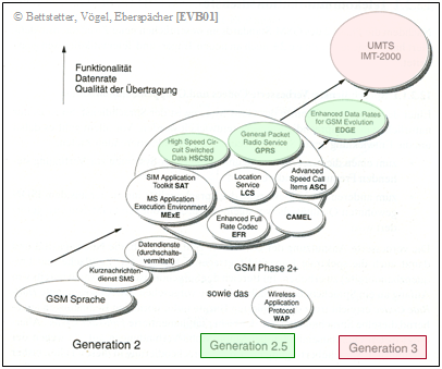
The graph from [EVB01][1] shows the further developments of GSM:
- The $\rm GSM$ system described so far in the third main chapter is limited to the first two generations. The $\rm phase \ 1$ included only basic teleservices and a few additional services that could be offered on a mandatory basis by all network operators at that time when GSM was launched in 1991.
- The standardization of the $\rm phase \ 2$ in the years from 1995 to 1997 already included the first further developments of the GSM standard. As a result, the additional services known from "ISDN" were also gradually made available for GSM and supplemented by some new features, such as call waiting or hold (Hold).
- In the years 1997-2000, new data services with higher data rates were developed, such as.
- "High Speed Circuit-Switched Data" (HSCSD),
- "General Packet Radio Service" (GPRS), and
- "Enhanced Data Rates for GSM Evolution" (EDGE).
These newer data services are classified as part of the $\rm phase \ 2+$ (or Generation 2.5) and are highlighted in green in the graphic.
- The third generation of mobile communications includes "UMTS" (Universal Mobile Telecommunications System). This standard enabled significantly higher data transmission rates than were possible with the GSM standard. It is discussed in detail in the fourth main chapter of this book. In the graphic above, this third-generation system is highlighted in red.
The innovations of the $\rm phase \ 2+$ affect almost all aspects of GSM, from radio transmission to call control. The new data services made possible by this are explained in more detail in the following sections.
High Speed Circuit–Switched Data (HSCSD)
The GSM data transmission standard $\rm High \ Speed \ Circuit-Switched \ Data$ (HSCSD), introduced in 1999, allowed the user data rate per connection to be increased from $9.6 \rm kbit/s$ to $14.4 \rm kbit/s$ when transmission conditions permitted.
By bundling several adjacent time slots, the data rate could be increased even further.
The data rate depends on how many channels the network operator provides for bundling or how many channels the HSCSD cell phone can process.
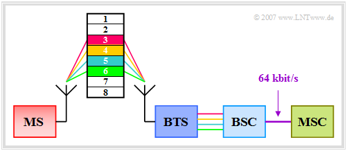
The graphic explains the principle of bundling multiple timeslots:
- Each of the eight physical channels (timeslots) in a frame provides a maximum $14.4 \rm kbit/s$ for data communication. HSCSD enables channel bundling by combining multiple timeslots, as is also used in ISDN. This is referred to as multislot capability.
- By interconnecting all eight channels, this would result in $\rm 8 - 14.4 \ kbit/s = 115.2 \ kbit/s$. However, since the connection between the Base Station Controller (BSC) and the Mobile Switching Center (MSC) is limited to $64 \rm kbit/s$ , one is limited to bundling four time slots, resulting in a maximum transmission rate of $57.6 \rm kbit/s$ .
- An advantage of HSCSD technology over packet-oriented GPRS (see next section) is the line-oriented data transmission. This is particularly advantageous for applications that require uniform bandwidths, since here the transmission channel does not have to be shared with anyone. Examples include video and image transmission.
- However, the higher transmission costs due to the occupancy of multiple channels are disadvantageous. These channels are therefore no longer available to other mobile subscribers. In a radio cell with high channel utilization, it can therefore happen that the bundling of multiple channels is prevented by the network operator.
General Packet Radio Service (GPRS)
With the GSM extension $\rm General \ Packet \ Radio \ Service$ (GPRS), packet-oriented data transmission was made possible for the first time in 2000. GPRS supports a large number of protocols (Internet Protocol, X.25, Datex-P, etc.) and allows mobile subscribers to communicate with external data networks (the Internet or internal company intranets). GPRS was an important intermediate step in the evolution of cellular mobile networks towards third generation and towards the mobile Internet.
A GPRS user benefits from shorter access times and the higher data rate $($to $21.4 \ \rm kbit/s)$ compared to conventional GSM $(9.6 \ \rm kbit/s)$ and HSCSD $(14.4 \ \rm kbit/s)$. With GPRS, the charges are not based on the connection duration, but on the actual amount of data transferred. Therefore, a radio channel does not have to be permanently reserved for a user (as is the case with HSCSD).
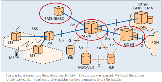
To introduce GPRS, some modifications and additions to the GSM network were necessary, as shown in the graphic "GPRS System Architecture" from [BVE99][2] summarized are:
- Blue lines describe payload and signaling data.
- The orange dotted connections denote signaling data.
- Gb, Gc, Gd, etc. indicate interfaces of GPRS.
To integrate GPRS into the existing GSM system architecture, a new class of network nodes is added to it.
The additional GPRS components - highlighted by red circles in the diagram - are explained here only in bullet points:
- The GPRS Support Nodes (GSN) are responsible for the transmission and traffic routing (routing) of data packets between the mobile stations and the external packet-switched data networks. Here, a distinction is made between SGSN and GGSN, which communicate with each other via an IP-based GPRS backbone network.
- The Serving GPRS Support Node (SGSN) is responsible for mobility management and performs a similar function for packet data services as the Mobile Switching Center (MSC) does for connection-oriented voice signals.
- The Gateway GPRS Support Node (GGSN) is the interface to foreign packet-oriented data networks. It converts the GPRS packets coming from the SGSN into the appropriate protocol (IP, X.25, ...) and sends them out to the Packet Data Network (PDN).
GPRS air interface
When a GPRS cell phone is switched on, it first performs the "Cell Selection" procedure by searching for a frequency channel with GPRS data. If such a channel has been found, then depending on the cell phone class, the cell phone must be manually set to GPRS services or it can automatically and dynamically switch between GPRS and GSM. A distinction is made between:
- Class $\rm A$ devices can handle GPRS data services and GSM transmission services simultaneously; channel resources are monitored in parallel in a packet-switched and circuit-switched manner.
- In class $\rm B$ the signaling channels of GSM and GPRS are monitored simultaneously as long as no service is switched through. However, parallel GSM/GPRS operation is not possible.
- In class $\rm C$ the subscriber must decide beforehand whether to use the mobile for GSM or GPRS, since signaling channels can no longer be monitored simultaneously.
To be able to switch the GSM radio interface to packet-oriented GPRS operation, the logical channels had to be extended. Logical GPRS channels can be recognized by a preceding "P", which indicates the packet-oriented operating mode. Almost for all logical GSM channels there is the corresponding GPRS equivalent:
- The Packet Data Traffic Channel (PDTCH) is used in GPRS as traffic channel for user data transfer. The corresponding GSM channel is called TCH.
- The signaling channels are divided into the Packet Broadcast Control Channel (PBCCH), the Packet Common Control Channel (PCCCH), and the Packet Dedicated Control Channel (PDCCH), as in GSM.
GPRS allows subscribers to exchange data with public data networks and, like GSM, uses GMSK modulation and the FDMA/TDMA combination with eight time slots per TDMA frame. The differences are as follows:
- In the GSM standard, each active mobile station is assigned exactly one time slot of a TDMA frame. This physical channel is reserved for the mobile station for the entire duration of a call, both in the uplink and in the downlink.
- In GPRS, up to eight time slots can be combined for rate enhancement. In addition, uplink and downlink are allocated separately. The physical channels are reserved only for the duration of the transmission of data packets and then released again.
GPRS channel coding
In contrast to conventional GSM $($with the data rate $9.6 \ \rm kbit/s)$ four possible coding schemes are defined for GPRS, which can be used depending on the reception quality:
- Coding scheme 1 $(\rm CS-1)$ with $9.05 \rm kbit/s$ (181 bits per 20 ms),
- Coding scheme 2 $(\rm CS-2)$ with $13.4 \rm kbit/s$ (268 bits per 20 ms),
- Coding scheme 3 $(\rm CS-3)$ with $15.6 \rm kbit/s$ (312 bits per 20 ms),
- Coding scheme 4 $(\rm CS-4)$ with $21.4 \rm kbit/s$ (428 bits per 20 ms).
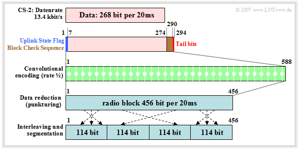
The smallest possible data rate is thus $9.05 \rm kbit/s$ ($\rm CS-1$, one time slot), the maximum is currently (2007) $171.2 \rm kbit/s$ ($\rm CS-4$, eight time slots). However, this theoretical speed is not achieved in practice, since most current GPRS phones only support a maximum net data rate of $13.4 \rm kbit/s$ ($\rm CS-2$). The graphic and the following explanations refer to this combination.
- The $268$ information bits are first supplemented by six precoded bits of the Uplink State Flag (USF), $16$ parity bit of the so-called Block Check Sequence (BCS) and four tail bits $(0000)$ . The latter are necessary for the termination of the convolutional codes.
- For channel coding, the convolutional code of code rate $R_{\rm C} = 1/2$ known from GSM is used. By this the total $294$ bits are doubled to $588$ bits and thus sufficiently protected against transmission errors.
- Followed by $132$ of these $588$ bits are punctured, so that finally a codeword of length $456$ bit $($bitrate $22.8 \ \rm kbit/s)$ results. This gives a resulting code rate (from convolutional encoders including puncturing) of $294/456 ≈ 65\%$.
- After channel coding, the codewords are fed to a block interleaver of depth $4$ . The interleaving scheme is identical for all four coding schemes.
Enhanced Data Rates for GSM Evolution
The last GSM extension $\rm Enhanced \ Data \ Rates \ for \ GSM-Evolution$ (EDGE) with the aim to increase the data transmission rate in GSM networks uses beside Gaussian Minimum Shift Keying (GMSK) as additional modulation method 8-Phase Shift Keying (8-PSK):
- With this one there are eight different symbols (with GMSK only two), distinguished by different phase positions at multiples of $45^\circ$ .
- This means that three data bits can be transmitted with each symbol, increasing the data rate by a factor of $3$ compared to GPRS.
With the definition of EDGE, HSCSD becomes Enhanced Circuit Switched Data (E-CSD) and GPRS becomes Enhanced-GPRS (E-GPRS). However, T-mobile is the only German network operator that currently (2007) offers EDGE on its network.
The graphic shows the Normal Burst of EDGE and E-GPRS respectively. One can see the following differences to the Normal Burst of GSM:
- The Normal Burst in EDGE consists of $468.75$ bits instead of the $156.25$ bits in GSM, from which the tripling of the data rate can be seen.
- As with GSM, there are two stealing flags. Tailbits, training sequence and Guard Period are each tripled. This leaves $57 - 3 + 2 = 173$ bits for the data field .
- Thus, channel coded data $($Coderate $R_{\rm C} =1/2)$ per $576.9\ \rm µ s$ are transmitted in E-GPRS in Normal Burst $346$ bits, which corresponds to a net data rate of approx. $60 \ \rm kbit/s$ .
Modulation and Coding Schemes for E–GPRS
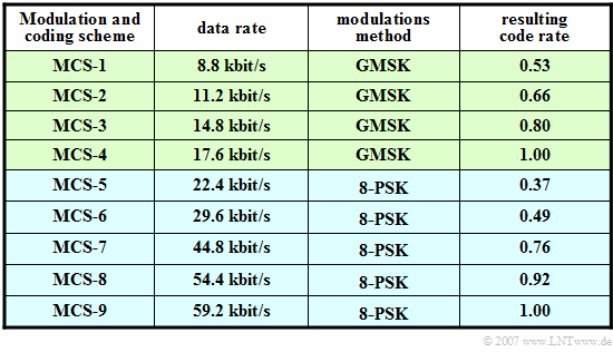
In E-GPRS, there are nine operator-selectable Modulation and Coding Schemes (MCS) depending on the channel coding and modulation schemes used.
The table shows the possible schemes of E-GPRS. From this it can be seen:
- The first four schemes, like GSM/GPRS, use the GMSK modulation scheme with one bit of information per channel use, while in $\rm MCS-5$, ... , $\rm MCS-9$ an eight-level phase modulation (8-PSK) is used and thus three bits per symbol are transmitted.
- The smaller the code rate, the greater the added redundancy and thus the data security. In particular, between $\rm MCS-4$ $(R_{\rm C} = 1)$ and $\rm MCS-5$ $(R_{\rm C} = 0.37)$ the code rate decreases significantly due to the more favorable modulation mode despite the higher net data rate (last column).
- The most elaborate mode $\rm MCS-9$ offers a data rate of $59.2 \rm kbit/s$ according to the table and theoretically allows the simultaneous occupation of eight time slots, which would mean a maximum net data rate of $473.6 \rm kbit/s$ . However, this mode $($with $R_{\rm C} = 1)$ is only applicable under extremely good conditions and eight time slots are also rarely available.
- With $\rm MCS-8$ and seven time slots, one can after all already achieve $380.8 \rm kbit/s$ and is thus in the order of magnitude of Universal Mobile Telecommunications System (UMTS), the best known standard of the third mobile radio generation, which currently offers $384 \rm kbit/s$ .
- EDGE uses the same frequencies as GSM, which is why this technology is particularly interesting for operators with existing GSM infrastructure who did not acquire any of the more expensive UMTS licenses in 2000 and still want to offer a sufficiently high data rate.
The UMTS system is described in detail in the following fourth main chapter.
Exercises for the chapter
Exercise 3.8: General Packet Radio Service
References
- ↑ Eberspächer, J.; Vögel, H.J.; Bettstetter, C.: Global System for Mobile Communication. 3rd ed. Stuttgart: Teubner, 2001.
- ↑ Bettstetter, C.; Vögel, H.J.; Eberspächer, J.: GSM Phase 2+ General Packet Radio Service GPRS: Architecture, Protocols, and Air Interface. In: IEEE Communications Surveys & Tutorials, Vol. 2 (1999) No. 3, pp. 2-14.
