Contents
- 1 # OVERVIEW OF THE THIRD MAIN CHAPTER #
- 2 Emergence and history of GSM
- 3 Cellular structure of GSM
- 4 GSM system architecture and network components
- 5 Base Station Subsystem (BSS)
- 6 Switching and Management Subsystem (SMSS)
- 7 Services provided by GSM
- 8 Die Teledienste von GSM
- 9 Aufgaben zum Kapitel
- 10 Quellenverzeichnis
# OVERVIEW OF THE THIRD MAIN CHAPTER #
The world's leading mobile communications standard at present (2011) is GSM - Global System for Mobile Communications. This was developed at the end of the 1980s and operates completely digitally. In 2011, it will be used in more than 200 countries, primarily for making calls via cell phones, but also for short messages (SMS) and for mobile circuit- or packet-switched data transmission (HSCSD, GPRS, EDGE).
This chapter contains in detail:
- the general description of GSM with important definitions of terms,
- the radio interface of GSM and its logical and physical channels,
- the main voice coding schemes for data compression,
- the overall transmission model of GSM for voice and data transmission,
- the channel coding used in GSM with interleaving and encryption, and
- the further developments of GSM such as HSCSD, GPRS and EDGE.
Emergence and history of GSM
The GSM standard was introduced around 1990 with the aim of offering a uniform pan-European mobile telephone system and network. Its use for data transmission was not initially the focus, but has since been steadily improved by additional specifications with regard to data rate.
The following is some data on the historical development of GSM:
1982 At the "Conférence Européenne des Postes et Télécommunications" (CEPT), the Groupe Spécial Mobile - abbreviated GSM - is established.
1987 A cooperation is formed between $17$ future operators from $15$ European countries and the GSM specification is started.
1990 Phase 1 of the GSM 900 specification (for 900 MHz) is completed and adaptation for the DCS 1800 (Digital Cellular System) system around the 1.8 GHz frequency begins.
1992 Most European GSM network operators start commercial operation, initially with voice services only. By the end of 1992, 13 networks are already "on air" in seven countries.
1995 Phase 2 of GSM standardization begins. This includes data, SMS roaming, fax and adaptations for GSM/PCS 1900, which goes online in the USA in the same year.
1999 With the introduction of WAP (Wireless Application Protocol) it becomes possible for the first time to transfer Internet content and other interactive service offerings to mobile devices.
2000 The GPRS (General Packet Radio Service) enhancement also improves and simplifies wireless access to packet-switched data networks such as IP or X.25 protocols.
2000 Phase 2+ simultaneously introduces EDGE (Enhanced Data Rates for GSM Evolution) which increases the data rate by a factor of about $3$ compared to GPRS.
2006 By 2006, the number of network operators had increased to $147$ in $213$ countries/territories worldwide, serving more than two billion subscribers. In Germany alone, there were already more than $70$ million GSM handsets at the end of 2005.
The GSM standards currently (2011) in use are:
- $\text{GSM 900}$: Frequency range around 900 MHz (D networks, in Germany TD1, Vodafone D2),
- $\text{GSM/DCS 1800}$: Frequency range around 1800 MHz (E networks, in Germany all operators),
- $\text{GSM/PCS 1900}$: Frequency range around 1900 MHz (mainly used in the USA).
Cellular structure of GSM
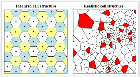
One characteristic of GSM is the cellular network structure, which is often idealized for simple calculations by hexagons according to the graphic on the left. This means that a coverage area with one base station per cell can be supplied without gaps if the range of the base station is at least as large as the cell radius.
This cellular structure results in the following consequences for the GSM system:
- The cell radius must be chosen smaller, the larger the carrier frequency is. For the D network $(f_{\rm T} ≈ 900 \ \rm MHz)$ the maximum cell radius is about $35 \ \rm km$, for the E network it is significantly smaller due to the higher frequency $(f_{\rm T} ≈ 1800 \ \ \rm MHz)$ with $8 \ \rm km$ .
- If a mobile subscriber moves in the area, it will traverse different cells and thus be in contact with different base stations. A problem not to be neglected is the so-called handover when crossing a cell boundary during a call.
- If the same carrier frequency is used in all cells, intercell interference can occur in case of overreach. Therefore, different frequencies are often used in neighboring cells. In the example above, three different frequencies are used, indicated by the colors white, yellow and blue. This example is based on the Reuse factor $3$.
The right graph shows a more realistic cell layout with different sized cells - depending on subscriber density and terrain topology.
- In addition, it can be seen that the base station does not always have to be located in the center of the cell.
- The colors "white" and "red" have no special meaning here.
GSM system architecture and network components
GSM is a hierarchically structured system of various network components. It has two main components, the mobile stations (MS, mobile subscribers) and the fixed GSM network. Each mobile station consists essentially of two entities:
- the Mobile Equipment (ME): each ME is assigned a unique number called the International Mobile Equipment Identity (IMEI).
- The subscriber identity module (SIM) is a small PIN-protected processor and memory responsible for user data allocation and authentication.
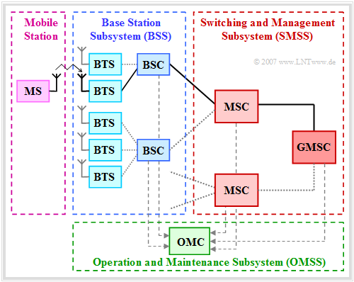
The diagram shows the structure for a so-called Public Land Mobile Network' (PLMN) of GSM, i.e. the GSM system architecture. This is designed for voice transmission, but is also suitable for data transmission to a limited extent.
From this graphic, one can see:
- The mobile station (MS) communicates via radio with the nearest Base Transceiver Station' (BTS).
- Multiple BTSs are grouped together by area and are subordinated as a unit to a Base Station Controller' (BSC).
- The Base Station Subsystem' (BSS) consists of a large number of BTSs and several BSCs. In the diagram, such a BSS is outlined in blue–dashed.
- Each BSC is finally connected to a Mobile Switching Center' (MSC), whose function is comparable to a switching node in the fixed network.
The fixed GSM infrastructure can be subdivided into three subnetworks:
- the Base Station Subsystem (BSS, radio network BSS) ⇒ For details see next page,
- the Switching and Management Subsystem' (SMSS) ⇒ For details see next page but one, and.
- the Operation and Maintenance Subsystem' (OMSS).
The OMSS provides subscriber setup, credential verification, device blocking, charging, network component maintenance, and traffic flow control. It includes the following components:
- The Operation and Maintenance Center (OMC) - outlined in green - monitors a portion of the overall cellular network and triggers the network's control functions. It is divided into the components OMC-B' ⇒ monitoring of Base Station Controller (BSC) and OMC-S' ⇒ control of Mobile Switching Center (MSC).
- Network control may also be centralized in a Network Management Center' (NMC) that is superior to the OMCs.
Other important functions/tasks of the Operation and Maintenance Center' (OMC) are the management of commercial operations, network configuration, security management and all maintenance activities regarding hardware and software.
Base Station Subsystem (BSS)
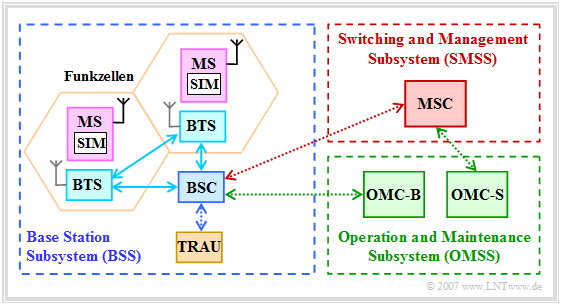
The following graphic shows in the left part a Base Station Subsystem, abbreviated BSS. Such a radio network consists of the following network components:
- The Base Transceiver Station' (BTS) provides at least one radio channel each for the useful traffic or the signaling. In addition to the RF part (transmitting and receiving equipment), it also has some components for signal and protocol processing. One or more antennas are connected to the BTS, which usually supply a 120° sector.
- To keep the base station units (BTS) small, the essential control and protocol intelligence is often shifted to the Base Station Controller' (BSC). It is quite possible for multiple BTSs to be controlled by a common BSC.
- Before the voice signal is transferred to the switching system, the Transcoding & Rate Adaption Unit' (TRAU) converts the rate of the GSM voice signal from $\text{13 kbit/s}$ to $\text{64 kbit/s}$. Furthermore, the TRAU also handles the rate adjustment for the data services.
Each BTS is assigned various parameters, namely:
- One or more radio cells are combined into one Location Area (LA). Each LA is assigned its own identification number - the so-called Location Area Identifier (LAI). This is broadcast regularly by the base station on the Broadcast Control Channel (BCCH).
- This also allows each mobile station to determine its current location via the LAI. When the Location Area changes, the mobile station requests a Location Update .
Other parameters of the Base Station Subsystem include:
- the Cell Allocation (CA):
Assignment of a set of frequencies to a BTS, - the Cell Identifier (CI):
Labeling of the individual cells within a LA, - the Base Transceiver Station Identity Code (BSIC):
Identifier of the base station.
Switching and Management Subsystem (SMSS)
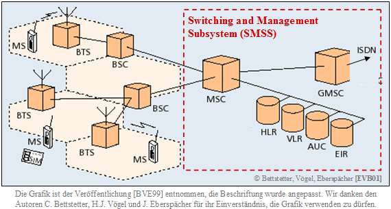
The Switching and Management Subsystem (SMSS) consists of the mobile switching centers (MSC or GMSC) and various databases (VLR, HLR, AUC, EIR, etc. ), as shown in the following diagram from [BVE99][1] shows.
Regarding this illustration, it should be noted:
- The Mobile Switching Center' (MSC) - i.e., the mobile switching center - performs the same switching functions as a fixed network switching node, e.g., path search and signal path switching. However, in addition, an MSC must also accommodate subscriber mobility (residence registration, handover when changing cells, and some more).
- The Gateway Mobile Switching Center' (GMSC) is responsible for the connection between the fixed network - for example the ISDN - and the mobile network. If, for example, a mobile subscriber is called from the fixed network, the GMSC determines the responsible MSC in the HLR (see below) and transfers the call.
MSC and GMSC have access to several databases:
- The Home Location Register (HLR) is a central register for subscriber data in a PLMN. It contains permanent data, but also temporary data needed for routing calls of own mobile subscribers.
- The Visitor Location Register (VLR) stores the data of all mobile stations that are currently in the administrative area of the associated MSC, i.e. also the subscribers of other network operators.
- The Authentication Center (AUC) is responsible for storing confidential data and keys.
- The Equipment Identity Register' (EIR) stores serial numbers (International Mobile Station Equipment Identity, IMEI) of the terminals.
There is constant data reconciliation between the databases (VLR, HLR, AUC, etc.) of two mobile switching centers involved in a voice connection. This requires various identifiers for all subscribers, for example:
- The Mobile Station Roaming Number (MSRN) is a temporary, residence-dependent ISDN number. It is assigned to each mobile station by the locally responsible VLR and forwarded by the HLR to the GMSC upon request. This is used to route calls to a mobile station.
- The Temporary Mobile Subscriber Identity (TMSI) is another identification number that is only valid in the territory of the VLR and is used instead of the International Mobile Subscriber Identity (IMSI) to address a mobile station.
$\text{Example 1:}$ We consider the mobile network of an operator $\rm A$ whose customer is the subscriber 1' .
- The Visited Location Register of operator $\rm A$ - abbreviated VLR(A) - contains information about the exact location (In which cell? Which BTS?) of all subscribers.
- For this subscriber 1' the entry in the Home Location Register HLR(A) matches VLR(A). Thus, operator $\rm A$ recognizes that subscriber 1 is its customer and a connection is established.
The subscriber 2 is a customer of another operator $\rm B$, who is currently in the network $\rm A$ by "roaming".
- The Visitor Location Register of operator $\rm A$ - abbreviated VLR(A) - contains information about the exact whereabouts of the foreign subscriber 2 and a copy of HLR(B) of operator $\rm B$.
- The operator $\rm A$ thus recognizes this foreign customer and gives him clearance for roaming in his network $\rm A$. The prerequisite, however, is that a roaming contract exists between the network operators
.
Services provided by GSM
Die GSM-Dienste sind in die drei Kategorien aufgeteilt:
- Bearer Services – Trägerdienste,
- Teleservices – Tele(matik)dienste,
- Supplementary Services – Zusatzdienste.
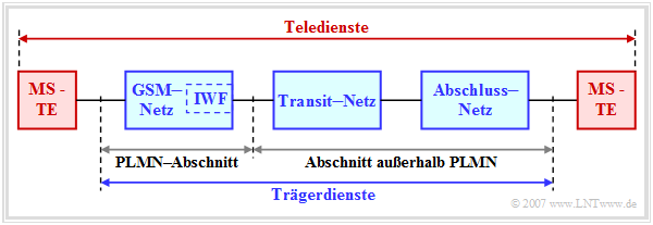
Träger– und Teledienste fasst man unter dem Oberbegriff „Telekommunikationsdienste” zusammen. Deshalb muss jedes Public Land Mobile Network (PLMN) die entsprechende Festnetz–Infrastruktur und eine Netzübergangsvermittlungsfunktion (Interworking Function, IWF) zur Verfügung stellen.
Die Trägerdienste sind für die Datenübertragung grundlegend. Sie stellen die notwendigen technischen Einrichtungen zum gesicherten Transport der Nutzdaten bereit. Zu den reinen Transportdiensten gehören:
- synchrone leitungsvermittelte Datenübertragung
(mit 2400, 4800 oder 9600 bit/s), - asynchrone leitungsvermittelte Datenübertragung
(mit 300 oder 1200 bit/s). - synchrone paketvermittelte Datenübertragung
(mit 2400, 4800 oder 9600 bit/s). - asynchrone paketvermittelte Datenübertragung
(mit 300 oder 9600 bit/s).
Die Trägerdienste werden dazu noch in zwei verschiedene Modi unterteilt:
- Im so genannten transparenten Modus besteht eine durch Vorwärtsfehlerkorrektur gesicherte Verbindung zwischen Endgerät und MSC. Dieser Modus ist durch eine konstante Bitrate, eine konstante Übertragungsverzögerung und – abhängig vom jeweiligen Kanalzustand – eine schwankende Bitfehlerhäufigkeit gekennzeichnet.
- Dagegen basiert der nichttransparente Modus auf dem Radio Link Protocol (RLP). Durch ein zusätzliches ARQ–Verfahren (Automatic Repeat Request) werden Blöcke mit zu vielen Bitfehlern zur Wiederübertragung angefordert, so dass die Netto–Bitrate und die Verzögerung stark von den Übertragungsbedingungen abhängen.
Die Teledienste von GSM
Die zweite Kategorie der GSM-Dienste sind Teledienste. Diese sind Ende-zu-Ende-Dienste, für die in der Regel keine Netzübergangsumsetzung (Interworking Function, IWF) erforderlich ist. In obiger Grafik bezeichnet „MS–TE“ das Terminal–Equipment der Mobilstation.
Die wichtigsten Teledienste sind:
- der Telefondienst. Dieser Basisdienst für die Übertragung digital–codierter Sprachsignale benutzt eine bidirektionale sowie symmetrische Punkt-zu-Punkt-Verbindung und bietet so genannte „Services” an, wie zum Beispiel Anrufumleitung, Anrufsperre und geschlossene Benutzergruppen;
- der Faxdienst, der zur Übertragung der Daten einen transparenten Trägerdienst nutzt;
- der Kurznachrichtendienst (englisch: Short Message Service, SMS), der von GSM seit 1996 bereitgestellt wird. Hiermit können Nachrichten mit einem verbindungslosen paketvermittelten Protokoll von oder zu einer Mobilstation übertragen werden. Hierzu muss ein Netzbetreiber ein Dienstzentrum (Service Center) einrichten.
Man unterscheidet zwei Typen von Kurznachrichten:
- Punkt-zu-Punkt-Nachrichten zwischen den Mobilstationen und einer Vermittlungsstelle mit einer maximalen Länge von 160 alphanumerischen Zeichen,
- Short Message Service Cell Broadcast (SMSCB). Diese Nachrichten werden nur in einem begrenzten, regionalen Gebiet ausgestrahlt und können von der Mobilstation nur im Ruhezustand empfangen werden. Die Länge ist auf 93 Zeichen beschränkt.
Die Zusatzdienste als dritte Kategorie der GSM–Dienste modifizieren und ergänzen die Funktionalität eines GSM–Telekommunikationsdienstes. GSM der Phase 1 bietet die gleichen Zusatzdienste an wie ISDN, beispielsweise Anrufanzeige, Rufumleitung (Call Forwarding) und Rufnummernsperre (Call Restriction).
Neuere GSM–Dienste der Phase 2+ sind:
- High Speed Circuit-Switched Data (HSCSD, Leitungsdatendienst),
- General Packet Radio Service (GPRS, Paketdatendienst), sowie
- Enhanced Data Rates for GSM Evolution (EDGE, höherratige Datenübertragung).
Aufgaben zum Kapitel
Aufgabe 3.1: GSM–Netzkomponenten
Quellenverzeichnis
- ↑ Bettstetter, C.; Vögel, H.J.; Eberspächer, J.: GSM Phase 2+ General Packet Radio Service GPRS: Architecture, Protocols, and Air Interface. In: IEEE Communications Surveys & Tutorials, Vol. 2 (1999) No. 3, pp. 2-14.
