Contents
Mutual information between continuous-value random variables
In the chapter Information-theoretical model of digital signal transmission the mutual information between the two discrete-value random variables $X$ and $Y$ was given, among other things, in the following form:
- $$I(X;Y) = \hspace{-0.4cm} \sum_{(x,\hspace{0.05cm} y) \hspace{0.1cm}\in \hspace{0.1cm}{\rm supp}\hspace{0.05cm} (P_{XY}\hspace{-0.08cm})} \hspace{-0.8cm} P_{XY}(x, y) \cdot {\rm log} \hspace{0.1cm} \frac{ P_{XY}(x, y)}{P_{X}(x) \cdot P_{Y}(y)} \hspace{0.05cm}.$$
This equation simultaneously corresponds to the Kullback–Leibler distance between the joint probability function $P_{XY}$ and the product of the two individual probability functions $P_X$ and $P_Y$ :
- $$I(X;Y) = D(P_{XY} \hspace{0.05cm} || \hspace{0.05cm}P_{X} \cdot P_{Y}) \hspace{0.05cm}.$$
In order to derive the mutual information $I(X; Y)$ between two continuous-value random variables $X$ and $Y$ , one proceeds as follows, whereby inverted commas indicate a quantised variable:
- One quantises the random variables $X$ and $Y$ $($with the quantisation intervals ${\it Δ}x$ and ${\it Δ}y)$ and thus obtains the probability functions $P_{X\hspace{0.01cm}′}$ and $P_{Y\hspace{0.01cm}′}$.
- The „vectors” $P_{X\hspace{0.01cm}′}$ and $P_{Y\hspace{0.01cm}′}$ become infinitely long after the boundary transitions ${\it Δ}x → 0, {\it Δ}y → 0$ , and the joint PMF $P_{X\hspace{0.01cm}′\hspace{0.08cm}Y\hspace{0.01cm}′}$ is then also infinitely extended in area.
- These boundary transitions give rise to the probability density functions of the continuous random variables according to the following equations:
- $$f_X(x_{\mu}) = \frac{P_{X\hspace{0.01cm}'}(x_{\mu})}{\it \Delta_x} \hspace{0.05cm}, \hspace{0.3cm}f_Y(y_{\mu}) = \frac{P_{Y\hspace{0.01cm}'}(y_{\mu})}{\it \Delta_y} \hspace{0.05cm}, \hspace{0.3cm}f_{XY}(x_{\mu}\hspace{0.05cm}, y_{\mu}) = \frac{P_{X\hspace{0.01cm}'\hspace{0.03cm}Y\hspace{0.01cm}'}(x_{\mu}\hspace{0.05cm}, y_{\mu})} {{\it \Delta_x} \cdot {\it \Delta_y}} \hspace{0.05cm}.$$
- The double sum in the above equation, after renaming $Δx → {\rm d}x$ or $Δy → {\rm d}y$ , becomes the equation valid for continuous value random variables:
- $$I(X;Y) = \hspace{0.2cm} \int \hspace{-0.9cm} \int\limits_{\hspace{-0.4cm}(x, y) \hspace{0.1cm}\in \hspace{0.1cm}{\rm supp} \hspace{0.03cm} (\hspace{-0.03cm}f_{XY}\hspace{-0.08cm})} \hspace{-0.6cm} f_{XY}(x, y) \cdot {\rm log} \hspace{0.1cm} \frac{ f_{XY}(x, y) } {f_{X}(x) \cdot f_{Y}(y)} \hspace{0.15cm}{\rm d}x\hspace{0.15cm}{\rm d}y \hspace{0.05cm}.$$
$\text{Conclusion:}$ By splitting this double integral, it is also possible to write for the transinformation:
- $$I(X;Y) = h(X) + h(Y) - h(XY)\hspace{0.05cm}.$$
The joint differential entropy
- $$h(XY) = -\hspace{0.2cm} \int \hspace{-0.9cm} \int\limits_{\hspace{-0.4cm}(x, y) \hspace{0.1cm}\in \hspace{0.1cm}{\rm supp} \hspace{0.03cm} (\hspace{-0.03cm}f_{XY}\hspace{-0.08cm})} \hspace{-0.6cm} f_{XY}(x, y) \cdot {\rm log} \hspace{0.1cm} \big[f_{XY}(x, y) \big] \hspace{0.15cm}{\rm d}x\hspace{0.15cm}{\rm d}y$$
and the two differential single entropies
- $$h(X) = -\hspace{-0.7cm} \int\limits_{x \hspace{0.05cm}\in \hspace{0.05cm}{\rm supp}\hspace{0.03cm} (\hspace{-0.03cm}f_X)} \hspace{-0.35cm} f_X(x) \cdot {\rm log} \hspace{0.1cm} \big[f_X(x)\big] \hspace{0.1cm}{\rm d}x \hspace{0.05cm},\hspace{0.5cm} h(Y) = -\hspace{-0.7cm} \int\limits_{y \hspace{0.05cm}\in \hspace{0.05cm}{\rm supp}\hspace{0.03cm} (\hspace{-0.03cm}f_Y)} \hspace{-0.35cm} f_Y(y) \cdot {\rm log} \hspace{0.1cm} \big[f_Y(y)\big] \hspace{0.1cm}{\rm d}y \hspace{0.05cm}.$$
On equivocation and irrelevance
We further assume the continuous value mutual information $I(X;Y) = h(X) + h(Y) - h(XY)$ . This representation is also found in the following diagram (left graph).
From this you can see that the mutual information can also be represented as follows:
- $$I(X;Y) = h(Y) - h(Y \hspace{-0.1cm}\mid \hspace{-0.1cm} X) =h(X) - h(X \hspace{-0.1cm}\mid \hspace{-0.1cm} Y)\hspace{0.05cm}.$$
These fundamental information-theoretical relationships can also be read from the graph on the right.
This directional representation is particularly suitable for message transmission systems.
The outflowing or inflowing differential entropy characterises
- the equivocation:
- $$h(X \hspace{-0.05cm}\mid \hspace{-0.05cm} Y) =\hspace{0.2cm} -\int \hspace{-0.9cm} \int\limits_{\hspace{-0.4cm}(x, y) \hspace{0.1cm}\in \hspace{0.1cm}{\rm supp}\hspace{0.03cm} (\hspace{-0.03cm}f_{XY}\hspace{-0.08cm})} \hspace{-0.6cm} f_{XY}(x, y) \cdot {\rm log} \hspace{0.1cm} \big [{f_{\hspace{0.03cm}X \mid \hspace{0.03cm} Y} (x \hspace{-0.05cm}\mid \hspace{-0.05cm} y)} \big] \hspace{0.15cm}{\rm d}x\hspace{0.15cm}{\rm d}y\hspace{0.05cm},$$
- the irrelevance:
- $$h(Y \hspace{-0.05cm}\mid \hspace{-0.05cm} X) =\hspace{0.2cm}- \int \hspace{-0.9cm} \int\limits_{\hspace{-0.4cm}(x, y) \hspace{0.1cm}\in \hspace{0.1cm}{\rm supp}\hspace{0.03cm} (\hspace{-0.03cm}f_{XY}\hspace{-0.08cm})} \hspace{-0.6cm} f_{XY}(x, y) \cdot {\rm log} \hspace{0.1cm} \big [{f_{\hspace{0.03cm}Y \mid \hspace{0.03cm} X} (y \hspace{-0.05cm}\mid \hspace{-0.05cm} x)} \big] \hspace{0.15cm}{\rm d}x\hspace{0.15cm}{\rm d}y\hspace{0.05cm}.$$
The significance of these two information-theoretic quantities will be discussed in more detail in task 4.5Z .
If one compares the graphical representations of the mutual information for
- discrete value random variables in the section [[Information_Theory/Anwendung_auf_die_Digitalsignalübertragung#Information-theoretical_model_of_digital_signal_transmission|Information-theoretical model of digital signal transmission] continuous value random variables according to the above diagram,
the only distinguishing feature is that each „capital $H$” (entropy; larger-equal zero) has been replaced by a „non-capital $h$” (differential entropy can be positive, negative or zero) .
- Otherwise, the mutual information is the same in both representations and $I(X; Y) ≥ 0$ always applies.
- In the following, we mostly use the binary logarithm ⇒ $\log_2$ and thus obtain the mutual information in „bit”.
Calculation of mutual information with additive noise
We now consider a very simple model of message transmission:
- The random variable $X$ stands for the (zero mean) transmission signal and is characterised by the PDF $f_X(x)$ and the variance $σ_X^2$ . The transmission power is $P_X = σ_X^2$.
- The additive noise $N$ is given by the PDF $f_N(n)$ and the noise power $P_N = σ_N^2$ .
- If $X$ and $N$ are assumed to be statistically independent ⇒ signal-independent noise, then $\text{E}\big[X · N \big] = \text{E}\big[X \big] · \text{E}\big[N\big] = 0$ .
- The received signal is $Y = X + N$. The output PDF $f_Y(y)$ can be calculated with the convolution operation ⇒ $f_Y(y) = f_X(x) ∗ f_N(n)$.
- For the received power (variance) holds:
- $$P_Y = \sigma_Y^2 = {\rm E}\big[Y^2\big] = {\rm E}\big[(X+N)^2\big] = {\rm E}\big[X^2\big] + {\rm E}\big[N^2\big] = \sigma_X^2 + \sigma_N^2 $$
- $$\Rightarrow \hspace{0.3cm} P_Y = P_X + P_N \hspace{0.05cm}.$$
The sketched density functions sketched (rectangular or trapezoidal) are only intended to clarify the calculation process and have no practical relevance.
To calculate the mutual information between input $X$ and output $Y$ there are three possibilities according to the graphic on the previous subchapter drei Möglichkeiten:
- Calculation according to $I(X, Y) = h(X) + h(Y) - h(XY)$:
- The first two terms can be calculated in a simple way from $f_X(x)$ and $f_Y(y)$ respectively. The joint differentrial entropy $h(XY)$ is problematic. For this, one needs the 2D joint PDF $f_{XY}(x, y)$, which is usually not given directly.
- Berechnung entsprechend $I(X, Y) = h(Y) - h(Y|X)$:
- Hierbei bezeichnet $h(Y|X)$ die differentielle Streuentropie. Es gilt $h(Y|X) = h(X + N|X) = h(N)$, so dass $I(X; Y)$ bei Kenntnis von $f_X(x)$ und $f_N(n)$ über die Gleichung $f_Y(y) = f_X(x) ∗ f_N(n)$ sehr einfach zu berechnen ist.
- Berechnung entsprechend $I(X, Y) = h(X) - h(X|Y)$:
- Nach dieser Gleichung benötigt man allerdings die differentielle Rückschlussentropie $h(X|Y)$, die schwieriger angebbar ist als $h(Y|X)$.
$\text{Fazit:}$ Im Folgenden verwenden wir die mittlere Gleichung und schreiben für die Transinformation zwischen dem Eingang $X$ und dem Ausgang $Y$ eines Nachrichtenübertragungssystems bei additiver und unkorrelierter Störung $N$:
- $$I(X;Y) \hspace{-0.05cm} = \hspace{-0.01cm} h(Y) \hspace{-0.01cm}- \hspace{-0.01cm}h(N) \hspace{-0.01cm}=\hspace{-0.05cm} -\hspace{-0.7cm} \int\limits_{y \hspace{0.05cm}\in \hspace{0.05cm}{\rm supp}(f_Y)} \hspace{-0.65cm} f_Y(y) \cdot {\rm log} \hspace{0.1cm} \big[f_Y(y)\big] \hspace{0.1cm}{\rm d}y +\hspace{-0.7cm} \int\limits_{n \hspace{0.05cm}\in \hspace{0.05cm}{\rm supp}(f_N)} \hspace{-0.65cm} f_N(n) \cdot {\rm log} \hspace{0.1cm} \big[f_N(n)\big] \hspace{0.1cm}{\rm d}n\hspace{0.05cm}.$$
Kanalkapazität des AWGN–Kanals
Spezifiziert man im bisherigen allgemeinen Systemmodell die Wahrscheinlichkeitsdichtefunktion der Störung (bzw. des Rauschens) als gaußisch entsprechend
- $$f_N(n) = \frac{1}{\sqrt{2\pi \sigma_N^2}} \cdot {\rm e}^{ - \hspace{0.05cm}{n^2}/(2 \sigma_N^2) } \hspace{0.05cm}, $$
so erhalten wir das rechts skizzierte Modell zur Berechnung der Kanalkapazität des so genannten AWGN–Kanals (Additive White Gaussian Noise). Meist ersetzen wir im Folgenden $\sigma_N^2$ durch $P_N$.
Aus vorherigen Abschnitten wissen wir:
- Die Kanalkapazität $C_{\rm AWGN}$ gibt die maximale Transinformation $I(X; Y)$ zwischen der Eingangsgröße $X$ und der Ausgangsgröße $Y$ des AWGN–Kanals an. Die Maximierung bezieht sich dabei auf die bestmögliche Eingangs–WDF. Somit gilt unter der Nebenbedingung der Leistungsbegrenzung:
- $$C_{\rm AWGN} = \max_{f_X:\hspace{0.1cm} {\rm E}[X^2 ] \le P_X} \hspace{-0.35cm} I(X;Y) = -h(N) + \max_{f_X:\hspace{0.1cm} {\rm E}[X^2] \le P_X} \hspace{-0.35cm} h(Y) \hspace{0.05cm}.$$
- Es ist bereits berücksichtigt, dass sich die Maximierung allein auf die differentielle Entropie $h(Y)$ ⇒ WDF $f_Y(y)$ bezieht. Bei gegebener Störleistung $P_N$ ist nämlich $h(N) = 1/2 · \log_2 (2π{\rm e} · P_N)$ eine Konstante.
- Das Maximum für $h(Y)$ erhält man für eine Gaußsche WDF $f_Y(y)$ mit $P_Y = P_X + P_N$ t, siehe Seite Maximale differentielle Entropie bei Leistungsbegrenzung:
- $${\rm max}\big[h(Y)\big] = 1/2 · \log_2 \big[2πe · (P_X + P_N)\big].$$
- Die Ausgangs–WDF $f_Y(y) = f_X(x) ∗ f_N(n)$ ist aber nur dann gaußförmig, wenn sowohl $f_X(x)$ als auch $f_N(n)$ Gaußfunktionen sind. Ein plakativer Merkspruch zur Faltungsoperation lautet nämlich: Gauß bleibt Gauß, und Nicht–Gauß wird nie (exakt) Gauß.
$\text{Fazit:}$ Beim AWGN–Kanal ⇒ Gaußsche Rausch-WDF $f_N(n)$ ergibt sich die Kanalkapazität genau dann, wenn die Eingangs–WDF $f_X(x)$ ebenfalls gaußförmig ist:
- $$C_{\rm AWGN} = h_{\rm max}(Y) - h(N) = 1/2 \cdot {\rm log}_2 \hspace{0.1cm} {P_Y}/{P_N}$$
- $$\Rightarrow \hspace{0.3cm} C_{\rm AWGN}= 1/2 \cdot {\rm log}_2 \hspace{0.1cm} ( 1 + P_X/P_N) \hspace{0.05cm}.$$
Parallele Gaußsche Kanäle
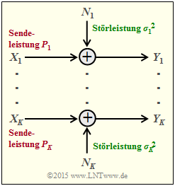
Wir betrachten nun entsprechend der Grafik $K$ parallele Gaußkanäle von $X_1 → Y_1$, ... , $X_k → Y_k$, ... , $X_K → Y_K$.
- Die Sendeleistungen in den $K$ Kanälen nennen wir
- $$P_1 = \text{E}[X_1^2], \hspace{0.15cm}\text{...}\hspace{0.15cm} ,\ P_k = \text{E}[X_k^2], \hspace{0.15cm}\text{...}\hspace{0.15cm} ,\ P_K = \text{E}[X_K^2].$$
- Die $K$ Störleistungen können ebenfalls unterschiedlich sein:
- $$σ_1^2, \hspace{0.15cm}\text{...}\hspace{0.15cm} ,\ σ_k^2, \hspace{0.15cm}\text{...}\hspace{0.15cm} ,\ σ_K^2.$$
Gesucht ist nun die maximale Transinformation $I(X_1, \hspace{0.15cm}\text{...}\hspace{0.15cm}, X_K\hspace{0.05cm};\hspace{0.05cm}Y_1, \hspace{0.15cm}\text{...}\hspace{0.15cm}, Y_K) $ zwischen
- den $K$ Eingangsgrößen $X_1$, ... , $X_K$ sowie
- den $K$ Ausgangsgrößen $Y_1$ , ... , $Y_K$,
die wir als die Gesamt–Kanalkapazität dieser AWGN–Konfiguration bezeichnen.
$\text{Vereinbarung:}$
Ausgegangen wird von Leistungsbegrenzung des Gesamtsystems. Das heißt:
Die Summe aller Leistungen $P_k$ in den $K$ Einzelkanälen darf den vorgegebenen Wert $P_X$ nicht überschreiten:
- $$P_1 + \hspace{0.05cm}\text{...}\hspace{0.05cm}+ P_K = \hspace{0.1cm} \sum_{k= 1}^K \hspace{0.1cm}{\rm E} \left [ X_k^2\right ] \le P_{X} \hspace{0.05cm}.$$
Unter der nur wenig einschränkenden Annahme unabhängiger Störquellen $N_1$, ... , $N_K$ kann für die Transinformation nach einigen Zwischenschritten geschrieben werden:
- $$I(X_1, \hspace{0.05cm}\text{...}\hspace{0.05cm}, X_K\hspace{0.05cm};\hspace{0.05cm}Y_1,\hspace{0.05cm}\text{...}\hspace{0.05cm}, Y_K) = h(Y_1, ... \hspace{0.05cm}, Y_K ) - \hspace{0.1cm} \sum_{k= 1}^K \hspace{0.1cm} h(N_k)\hspace{0.05cm}.$$
Dafür istn folgende obere Schranke angebbar:
- $$I(X_1,\hspace{0.05cm}\text{...}\hspace{0.05cm}, X_K\hspace{0.05cm};\hspace{0.05cm}Y_1, \hspace{0.05cm}\text{...} \hspace{0.05cm}, Y_K) \hspace{0.2cm} \le \hspace{0.1cm} \hspace{0.1cm} \sum_{k= 1}^K \hspace{0.1cm} \big[h(Y_k - h(N_k)\big] \hspace{0.2cm} \le \hspace{0.1cm} 1/2 \cdot \sum_{k= 1}^K \hspace{0.1cm} {\rm log}_2 \hspace{0.1cm} ( 1 + {P_k}/{\sigma_k^2}) \hspace{0.05cm}.$$
- Das Gleichheitszeichen (Identität) gilt bei mittelwertfreien Gaußschen Eingangsgrößen $X_k$ sowie bei statistisch voneinander unabhängigen Störungen $N_k$.
- Man kommt von dieser Gleichung zur maximalen Transinformation ⇒ Kanalkapazität, wenn man die gesamte Sendeleistung $P_X$ unter Berücksichtigung der unterschiedlichen Störungen in den einzelnen Kanälen $(σ_k^2)$ bestmöglich aufteilt.
- Dieses Optimierungsproblem lässt sich wieder mit dem Verfahren der Lagrange–Multiplikatoren elegant lösen. Das folgende Beispiel erläutert nur das Ergebnis.
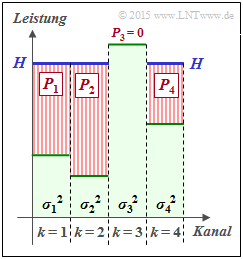
$\text{Beispiel 1:}$ Wir betrachten $K = 4$ parallele Gaußkanäle mit vier unterschiedlichen Störleistungen $σ_1^2$, ... , $σ_4^2$ gemäß der nebenstehenden Abbildung (schwach–grüne Hinterlegung).
- Gesucht ist die bestmögliche Aufteilung der Sendeleistung auf die vier Kanäle.
- Würde man dieses Profil langsam mit Wasser auffüllen, so würde das Wasser zunächst nur in den $\text{Kanal 2}$ fließen.
- Gießt man weiter, so sammelt sich auch im $\text{Kanal 1}$ etwas Wasser an und später auch im $\text{Kanal 4}$.
Die eingezeichnete „Wasserhöhe” $H$ beschreibt genau den Zeitpunkt, zu dem die Summe $P_1 + P_2 + P_4$ der insgesamt zur Verfügung stehenden Sendeleistung $P_X$ entspricht:
- Die optimale Leistungsaufteilung für dieses Beispiel ergibt $P_2 > P_1 > P_4$ sowie $P_3 = 0$.
- Erst bei größerer Sendeleistung $P_X$ würde auch dem dritten Kanal eine kleine Leistung $P_3$ zugewiesen.
Man bezeichnet dieses Allokationsverfahren als Water–Filling–Algorithmus.
$\text{Beispiel 2:}$ Werden alle $K$ Gaußkanäle in gleicher Weise gestört ⇒ $σ_1^2 = \hspace{0.15cm}\text{...}\hspace{0.15cm} = σ_K^2 = P_N$, so sollte man natürlich die gesamte zur Verfügung stehende Sendeleistung $P_X$ gleichmäßig auf alle Kanäle verteilen: $P_k = P_X/K$. Für die Gesamtkapazität erhält man dann:
- $$C_{\rm Gesamt} = \frac{ K}{2} \cdot {\rm log}_2 \hspace{0.1cm} ( 1 + \frac{P_X}{K \cdot P_N}) \hspace{0.05cm}.$$
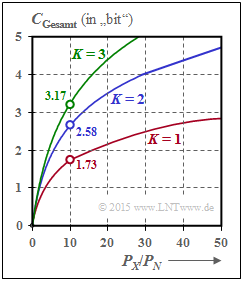
Die Grafik zeigt die Gesamtkapazität als Funktion von $P_X/P_N$ für $K = 1$, $K = 2$ und $K = 3$:
- Bei $P_X/P_N = 10 \ ⇒ \ 10 · \text{lg} (P_X/P_N) = 10 \ \text{dB}$ wird die Gesamtkapazität um ca. $50\%$ größer, wenn man die Gesamtleistung $P_X$ auf zwei Kanäle gleichmäßig aufteilt: $P_1 = P_2 = P_X/2$.
- Im Grenzfall $P_X/P_N → ∞$ nimmt die Gesamtkapazität um den Faktor $K$ zu ⇒ Verdoppelung bei $K = 2$.
Die beiden identischen und voneinander unabhängigen Kanäle kann man auf unterschiedliche Weise realisieren, zum Beispiel durch Multiplexverfahren in Zeit, Frequenz oder Raum.
Der Fall $K = 2$ lässt sich aber auch durch die Verwendung orthogonaler Basisfunktionen wie „Cosinus” und „Sinus” verwirklichen wie zum Beispiel bei
- der Quadratur–Amplitudenmodulation (QAM) oder
- einer mehrstufigen Phasenmodulation wie QPSK oder 8–PSK.
Aufgaben zum Kapitel
Aufgabe 4.5: Transinformation aus 2D-WDF
Aufgabe 4.5Z: Nochmals Transinformation
Aufgabe 4.6: AWGN–Kanalkapazität
Aufgabe 4.7: Mehrere parallele Gaußkanäle
Aufgabe 4.7Z: Zum Water–Filling–Algorithmus


