Some Results from Line Transmission Theory
Contents
# OVERVIEW OF THE FOURTH MAIN CHAPTER #
A special case of causal and time-invariant systems are »electrical cables«. Here, due to the Hilbert transformation must always be assumed:
- a »complex-valued frequency response« $H(f)$ and
- strongly »unbalanced impulse responses« $h(t)$.
The fourth chapter presents a summary of »conducted transmission channels«, specifically
- important »results and descriptive quantities of Line Transmission Theory«, in particular
- primary line parameters,
- complex propagation function $($per unit length$)$,
- attenuation function $($per unit length$)$,
- phase function $($per unit length$)$,
- wave impedance, and
- the operational attenuation to take account of mismatches and reflections;
- the »frequency responses and impulse responses of coaxial cables«, in which, due to good shielding, all other interferences are negligible compared to thermal noise $($Gaussian distributed and white$)$, and
- the »description of symmetrical copper cables«, which are the main transmission medium in the »access network of telecommunication systems«. Since many pairs run in parallel in a cable, »crosstalk« occurs due to capacitive and inductive couplings.
Equivalent circuit diagram of a short transmission line section
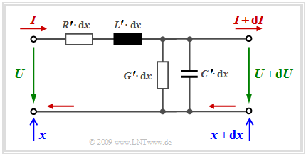
To derive the line equations, first a very short line section of length ${\rm d}x$ is considered, so that the values for voltage and current
- at the beginning of the line $(U$ resp. $I$ at $x)$ and
- the end of the line $(U + {\rm d}U$ and $I + {\rm d}I$ at $x + {\rm d}x)$
differ only slightly. The diagram below shows the underlying model.
$\text{Or in other words:}$
Let the line length ${\rm d}x$ be very small compared to the wavelength $\lambda$ of the electromagnetic wave propagating along the line, which results because
- there is a magnetic field connected to the current,
- the voltage between the conductors causes an electric field.
All »infinitesimal components« in the equivalent circuit sketched on the right are location-independent for homogeneous lines:
- The inductance of the considered line section is $L\hspace{0.05cm}' \cdot {\rm d}x$, where $L'$ is called »serial inductance« per unit length.
- Similarly, the »parallel capacitance« per unit length $(C\hspace{0.05cm}')$ is an infinitesimally small quantity which, similar to $L'$, depends only slightly on frequency.
- The »parallel conductance« per unit length $(G\hspace{0.05cm}')$ takes into account the losses of the dielectric between the wires. It increases approximately proportionally with frequency.
- By far the largest $($negative$)$ influence on signal transmission is the »serial resistance« per unit length $(R\hspace{0.05cm}')$, which increases almost proportionally with the root of the frequency for high frequencies due to the so-called »skin effect«.
From the mesh and node equations of the line section, $ω = 2πf$ results in the two difference equations:
- $$ U = I \cdot (R\hspace{0.05cm}' + {\rm j} \cdot \omega L\hspace{0.05cm}') \cdot {\rm d}x + (U + {\rm d}U)\hspace{0.05cm},$$
- $$ I = (U + {\rm d}U) \cdot (G\hspace{0.05cm}' + {\rm j} \cdot \omega C\hspace{0.05cm}') \cdot {\rm d}x + (I + {\rm d}I)\hspace{0.05cm}. $$
For very short line sections $($infinitesimally small ${\rm d}x)$ and neglecting the small second order quantities $($for example ${\rm d}U \cdot {\rm d}x)$, one can now form two differential quotients whose joint consideration leads to a second order linear differential equation:
- $$\frac{ {\rm d}U}{ {\rm d}x} = - (R\hspace{0.05cm}' + {\rm j} \cdot \omega L\hspace{0.05cm}') \cdot I,\hspace{0.5cm} \frac{ {\rm d}I}{ {\rm d}x} = - (G\hspace{0.05cm}' + {\rm j} \cdot \omega C\hspace{0.05cm}') \cdot U\hspace{0.3cm} \Rightarrow \hspace{0.3cm}\frac{{\rm d}^2U}{{\rm d}x^2} = (R\hspace{0.05cm}' + {\rm j} \cdot \omega L\hspace{0.05cm}') \cdot (G\hspace{0.05cm}' + {\rm j} \cdot \omega C\hspace{0.05cm}') \cdot U\hspace{0.05cm}.$$
The solution of this differential equation is:
- $$U(x) = U_{\rightarrow}(x=0) \cdot {\rm e}^{-\hspace{0.02cm}\gamma \hspace{0.03cm} \cdot \hspace{0.05cm}x} + U_{\leftarrow}(x=0) \cdot {\rm e}^{\gamma \hspace{0.03cm} \cdot \hspace{0.05cm}x} \hspace{0.05cm}.$$
The voltage curve depends not only on the location $x$ but also on the frequency $f$ which is not explicitly noted in the equation given here.
Formula-wise, this frequency dependence is captured by the »complex propagation function« per unit length:
- $$\gamma(f) = \sqrt{(R\hspace{0.05cm}' + {\rm j} \cdot 2\pi f \cdot L\hspace{0.05cm}') \cdot (G\hspace{0.05cm}' + {\rm j} \cdot 2\pi f \cdot C\hspace{0.05cm}')} = \alpha (f) + {\rm j} \cdot \beta (f)\hspace{0.05cm}.$$
The last two equations together describe the voltage curve along the line, which results from the superposition of a wave $U_→(x)$ running in the positive $x$ direction and the wave $U_←(x)$ in the opposite direction.
- The real part $α(f)$ of the complex propagation function $γ(f)$ attenuates the propagating wave and is therefore called »attenuation function« per unit length. This always even function ⇒ $α(-f) = α(f)$ results from the above $γ(f)$ equation as follows:
- $$\alpha(f) = \sqrt{{1}/{2}\cdot \left (R\hspace{0.05cm}' \cdot G\hspace{0.05cm}' - \omega^2 \cdot L\hspace{0.05cm}' \cdot C\hspace{0.05cm}'\right)+ {1}/{2} \cdot \sqrt{(R\hspace{0.05cm}'\hspace{0.05cm}^2 + \omega^2 \cdot L\hspace{0.05cm}'\hspace{0.05cm}^2) \cdot (G\hspace{0.05cm}'\hspace{0.05cm}^2 + \omega^2 \cdot C\hspace{0.05cm}'\hspace{0.05cm}^2)}} \bigg |_{\hspace{0.05cm}\omega \hspace{0.05cm}= \hspace{0.05cm}2\pi f}.$$
- The odd imaginary part ⇒ $β(- f) = - β(f)$ is called »phase function« per unit length and describes the phase rotation of the wave along the line:
- $$\beta(f) = \sqrt{ {1}/{2}\cdot \left (-R\hspace{0.05cm}' \cdot G\hspace{0.05cm}' + \omega^2 \cdot L\hspace{0.05cm}' \cdot C\hspace{0.05cm}'\right)+ {1}/{2} \cdot \sqrt{(R\hspace{0.05cm}'\hspace{0.05cm}^2 + \omega^2 \cdot L\hspace{0.05cm}'\hspace{0.05cm}^2) \cdot (G\hspace{0.05cm}'\hspace{0.05cm}^2 + \omega^2 \cdot C\hspace{0.05cm}'\hspace{0.05cm}^2)}} \bigg |_{\hspace{0.05cm}\omega \hspace{0.05cm}= \hspace{0.05cm}2\pi f}.$$
Wave impedance and reflections
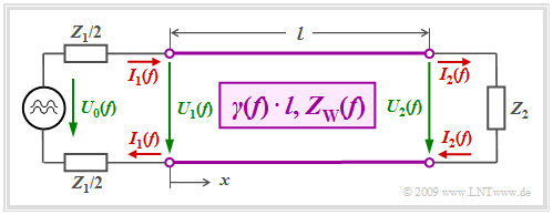
We consider a homogeneous line of length $l$ with a harmonic oscillation $U_0(f)$ of frequency $f$ applied to its input.
- The transmitter has internal resistance $Z_1$.
- The receiver has the input impedance $Z_2$.
- This is also the terminating resistor of the line.
- We assume for simplicity that $Z_1$ and $Z_2$ are real resistors.
Current and voltage of the outgoing wave and of the return wave are linked via the »wave impedance« $Z_{\rm W}(f)$:
- $$I_{\rightarrow}(x, f) = \frac{U_{\rightarrow}(x, f)}{Z_{\rm W}(f)}\hspace{0.05cm}, \hspace{1cm} I_{\leftarrow}(x, f) = \frac{U_{\leftarrow}(x, f)}{Z_{\rm W}(f)}\hspace{0.05cm}.$$
The following applies to the »wave impedance«:
- $$Z_{\rm W}(f) = \sqrt{\frac {R\hspace{0.05cm}' + {\rm j} \cdot \omega L\hspace{0.05cm}'}{G\hspace{0.05cm}' + {\rm j} \cdot \omega C\hspace{0.05cm}'}} \hspace{0.1cm}\bigg |_{\hspace{0.05cm}\omega \hspace{0.05cm}= \hspace{0.05cm}2\pi f}.$$
- The wave traveling in the positive $x$–direction is generated by the »AC voltage source« at the beginning of the line $($at $x = 0)$.
- The backward wave is only generated by the »reflection of the forward wave« at the end of the line $($at $x = l)$:
- $$U_{\leftarrow}(x = l) = {U_{\rightarrow}(x = l)}\cdot \frac{Z_2 -Z_{\rm W}(f)}{Z_2 + Z_{\rm W}(f)}\hspace{0.05cm}.$$
- At this point, the terminating resistor $Z_2$ forces a fixed relationship between voltage and current:
- $$U_2(f) = Z_2 · I_2(f).$$
$\text{Conclusion:}$ It can be seen from the above equation that there is »no returning wave« only for $Z_2 = Z_{\rm W}(f)$ .
- Such resistance matching is always sought in Communications Engineering.
- This matching is not possible over a larger frequency range with fixed termination $Z_2$ due to the frequency dependence of the wave impedance $Z_{\rm W}(f)$ .
In the following, these equations are explained with an example.
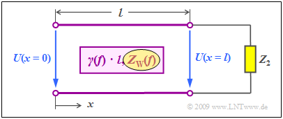
$\text{Example 1:}$ We consider the case shown on the right:
- The terminating resistor $Z_2$ of the line $($at the same time the input impedance of the following receiver$)$ differs from the wave impedance $Z_{\rm W}(f)$.
- We disregard the mismatch at the beginning of the line.
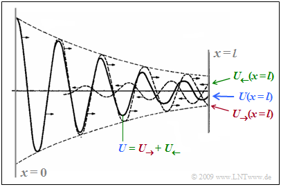
The diagram below from [Han17][1] is intended to make clear how the resulting wave $U(x)$ - shown as a solid curve - differs from the outgoing wave $U_→(x)$.
To clarify:
- Marked in red is the outgoing wave $U_→(x)$ which starting from the transmitter ⇒ $U_→(x = 0)$ , attenuates along the line. $U_→(x = l)$ denotes the wave at the end of the line.
- Due to the mismatch there is the returning wave $U_←(x)$ from the end of the line to the transmitter, marked in green ⇒ »reflection« . For this the following applies at $x = l$:
- $$U_{\leftarrow}(x = l) = {U_{\rightarrow}(x = l)}\cdot \frac{Z_2 -Z_{\rm W}(f)}{Z_2 + Z_{\rm W}(f)}\hspace{0.05cm}.$$
- The blue wave $U(x)$ results from the in–phase addition of these two parts which are not visible by themselves. As $x$ increases, $U(x)$ becomes smaller, as does $U_→(x)$ due to line attenuation. Also the returning wave $U_←(x)$ is attenuated with increasing length $($here from right to left$)$.
Lossless and low-loss lines
$\text{Definition:}$ $R\hspace{0.05cm}' \approx 0$ and $G\hspace{0.05cm}' \approx 0$ can be assumed for very short coaxial lines, such as those used for high-frequency measuring connections in the laboratory.
For such a »lossless line«, the above equations simplify:
»Attenuation function per unit length«: $($please note the difference between "a" and "alpha"$)$.
- $$\alpha(f) = \frac{\text{attenuation function }\ a(f)} {\text{length }\ l } = 0\hspace{0.05cm}.$$
»Phase function per unit length«:
- $$\beta(f) = \frac{\text{phase function }\ b(f)} {\text{length }\ l } = 2\pi \cdot f \cdot \sqrt{L\hspace{0.05cm}' \cdot C\hspace{0.05cm}' }\hspace{0.05cm}, $$
»Wave impedance«:
- $$Z_{\rm W}(f) = \sqrt{ {L\hspace{0.05cm}'}/{ C\hspace{0.05cm}'} }\hspace{0.05cm}.$$
If $L\hspace{0.05cm}'$ and $C\hspace{0.08cm}'$ are constant in the considered frequency range, the $($real$)$ wave impedance $Z_{\rm W}(f)=Z_{\rm W}$ is also frequency–independent and the phase function per unit length ⇒ $β(f)$ is proportional to the frequency.
- This means that a lossless line is always distortion–free.
- The output signal can only have a »delay time« compared to the input signal.
- Common wave impedances are $Z_{\rm W} = 50 \ \rm Ω$, $Z_{\rm W} = 75 \ \rm Ω$ and $Z_{\rm W} = 150 \ \rm Ω$.
- One speaks of a »low-loss line« when the line is somewhat longer, but cannot yet be called "long".
$\text{Example 2:}$ The given formula for the »attenuation function per unit length« ⇒ $\alpha(f)$ is now to be evaluated for the case of constant primary line parameters, which does not quite correspond to reality.
- Above a »characteristic frequency« $f_∗$ that depends on $R\hspace{0.05cm}', \ L\hspace{0.05cm}', \ G\hspace{0.08cm}'$ and $C\hspace{0.08cm}'$,
- the serial resistance per unit length $(R\hspace{0.05cm}')$ can be assumed to be very small compared to $ωL\hspace{0.05cm}'$, and
- the parallel conductance per unit length $(G\hspace{0.05cm}')$ can be assumed to be very small compared to $ωC\hspace{0.08cm}'$.
- ⇒ This gives the approximate formula often referred to as »weak attenuation«, valid for $(f \gg f_∗)$:
- $$\alpha_{_{ {\rm I} } }(f) = {1}/{2} \cdot \left [R\hspace{0.05cm}' \cdot \sqrt{ {C\hspace{0.05cm}'}/{ L\hspace{0.05cm}'} } + G\hspace{0.08cm}' \cdot \sqrt{ {L\hspace{0.05cm}'}/{ C\hspace{0.08cm}'} }\right ] \hspace{0.05cm}.$$
- On the other hand, for small frequencies $(f < f_∗)$
- the serial resistance per unit length $(R\hspace{0.05cm}')$ is much larger than $ωL\hspace{0.05cm}'$, and
- the parallel conductance per unit length $(G\hspace{0.05cm}')$ is much larger than $ ωC\hspace{0.08cm}'$.
- ⇒ A second upper bound is obtained, often referred to in literature as »strong attenuation«, valid for $(f \ll f_∗)$:
- $$\alpha_{_{ {\rm II} } }(f) = \sqrt{ 1/2 \cdot \omega \cdot {R\hspace{0.05cm}' \cdot C\hspace{0.08cm}'} }\hspace{0.1cm} \bigg \vert_{\omega \hspace{0.05cm}= \hspace{0.05cm}2\pi f}\hspace{0.05cm}.$$
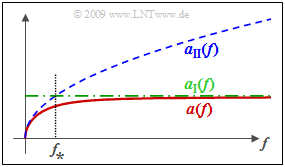
The diagram shows the attenuation function $α(f)$ at constant primary line parameters according to the exact $($but more complicated$)$ formula and the two bounds $α_{\rm I}(f)$ and $α_{\rm II}(f)$. One recognizes from this representation:
- Both $α_{\rm I}(f)$ and $α_{\rm II}(f)$ are upper bounds for $α(f)$.
- The characteristic frequency $f_∗$ is the intersection of $α_{\rm I}(f)$ and $α_{\rm II}(f)$.
- For $f \gg f_∗$ holds $α(f) ≈ α_{\rm I}(f)$, whereas for $f \ll f_∗$ $α(f) ≈ α_{\rm II}(f)$.
Influence of reflections - operational attenuation
The choice of the terminating resistor $Z_2(f) = Z_{\rm W}(f)$ prevents the generation of a reflected wave at the end of the line. In practice, however, an exact matching of these resistors is usually possible only in a very limited frequency range, for example
- due to the complicated frequency dependence of the wave impedance,
- with cables of different designs along a connection,
- when taking into account manufacturing tolerances.
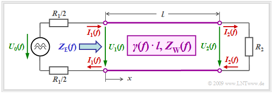
Therefore, in real systems the internal resistance $R_1$ of the source and the terminating resistance $R_2$ are usually chosen to be real and constant. For example, in the communication system »Integrated Services Digital Network« $\rm (ISDN)$ $R_1 = R_2 = 150 \ \rm Ω$ has been set.
This circuit simplification has the following effects:
- The input impedance $Z_{\rm E}(f)$ of the line as seen from the source depends
- on the complex propagation function per unit length ⇒ $γ(f)$,
- on the line length $l$,
- on the wave impedance $Z_{\rm W}(f)$, and
- on the terminating resistance $R_2$:
- $$Z_{\rm E}(f) = Z_{\rm W}(f)\cdot \frac {R_2 + Z_{\rm W}(f) \cdot {\rm tanh}(\gamma(f) \cdot l)} {Z_{\rm W}(f)+ R_2 \cdot {\rm tanh}(\gamma(f) \cdot l)} \hspace{0.05cm}, \hspace{0.5cm} {\rm with}\hspace{0.5cm}{\rm tanh}(x) = \frac {{\rm sinh}(x)}{{\rm cosh}(x)} = \frac {{\rm e}^{x}-{\rm e}^{-x}}{{\rm e}^{x}+{\rm e}^{-x}}\hspace{0.05cm}, \hspace{0.3cm}x \in {\cal C} \hspace{0.05cm}.$$
- This circuit-related simplification ⇒ $Z_{\rm 2}(f) = R_2$ results in reflections at the end of the line.
- These reduce the power available at the receiver and thus increase the line attenuation.
- For the evaluation of such a mismatched system, the »operational attenuation« has been defined as follows:
- $${ a}_{\rm B}(f) \hspace{0.15cm}{\rm in} \hspace{0.15cm}{\rm Neper}\hspace{0.15cm}{\rm (Np)} = {\rm ln}\hspace{0.1cm}\frac {|U_0(f)|}{2 \cdot |U_2(f)|} \cdot \sqrt{{R_2}/{R_1}} = \alpha (f ) \cdot l + {\rm ln}\hspace{0.1cm}|q_1(f)| + {\rm ln}\hspace{0.1cm}|q_2(f)| + {\rm ln}\hspace{0.1cm}|1 - r_1(f) \cdot r_2(f) \cdot {\rm e}^{-\gamma(f) \hspace{0.05cm} \cdot \hspace{0.05cm}l}| \hspace{0.05cm}.$$
$\text{Example 3:}$ This equation will now be discussed using the above block diagram $($valid for ISDN$)$. We consider the general case of a mismatched system:
- $$R_2 ≠ Z_{\rm W}(f).$$
- The »operational attenuation« ${ a}_{\rm B}(f)$ sets the actual active power transmitted from the transmitter to the receiver in relation to the best possible case
$($negligible line length, full matching$)$.
- For resistance matching, the operational attenuation is equal to the »wave attenuation«. In this case, only the first term of the above equation is effective:
- $$a_{\rm B}(f) = \alpha (f ) \cdot l \hspace{0.05cm}.$$
- The second and third terms take into account the power losses due to reflection at the transitions from the transmitter to the line and from the line to the receiver.
For these two »reflection losses« holds:
- $$q_1(f)= \frac {R_1 + Z_{\rm W}(f)}{2 \cdot \sqrt{R_1 \cdot Z_{\rm W}(f)} } \hspace{0.05cm}, \hspace{0.3cm}q_2(f)= \frac {R_2 + Z_{\rm W}(f)}{2 \cdot \sqrt{R_2 \cdot Z_{\rm W}(f)} } \hspace{0.05cm}.$$
- The »interaction attenuation« $($fourth term$)$ describes the effect of a multiple reflected wave, which – depending on the line length – is constructively or destructively superimposed on the useful signal at the receiver. The following applies to these reflection factors:
- $$r_1(f)= \frac {R_1 - Z_{\rm W}(f)}{R_1 + Z_{\rm W}(f)} \hspace{0.05cm}, \hspace{0.3cm}r_2(f)= \frac {R_2 - Z_{\rm W}(f)}{R_2 + Z_{\rm W}(f)} \hspace{0.05cm}.$$
The various components of the operational attenuation $a_{\rm B}(f)$ are calculated in $\text{Exercise 4.3}$ for a practical example.
$\text{Please note:}$ In the following chapters for
- »coaxial cables« and
- »balanced copper pairs«
only the »wave attenuation $α(f)\cdot l$« is further considered and thus the effects of mismatching are neglected.
Exercises for the chapter
Exercise 4.1: Attenuation Function
Exercise 4.1Z: Transmission Behavior of Short Cables
Exercise 4.3: Operational Attenuation
References
- ↑ Hanik, N.: Leitungsgebundene Übertragungstechnik. Lecture notes. Chair of Communications Engineering, TU München, 2017.
