Contents
Vestigial sideband amplitude modulation
When transmitting signals using single-sideband modulation $\rm (SSB–AM)$ the following problems occur:
- To suppress the unwanted sideband, a filter with a very high edge slope must be used.
- Such steep-edged filters exhibit strong group delay distortions, especially at the limit of the passband.
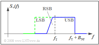
The problem can be greatly mitigated if instead of single-sideband AM one uses "vestigial sideband amplitude modulation" $\rm (VSB–AM)$, as shown in the adjacent graph.
The present description is based on the textbook [Mäu88][1]. According to it, the VSB-AM can be characterized as follows:
- A certain frequency range of the actually suppressed sideband – in the considered example of the LSB – is additionally used with a relatively flat decreasing transfer function.
- On the receiver side, a selection curve linearly increasing in frequency with a so-called "Nyquist edge" is used in the transition range from the suppressed sideband to the transmitted sideband.
- The demodulation performs a convolution of the sidebands around the carrier, so that as a result the message content of a band with the same amplitude for all frequencies is obtained.
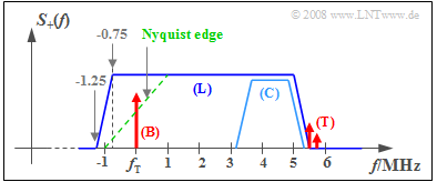
$\text{Example 1:}$ The vestigial sideband method is used for (analog) color television, whose frequency spectrum according to the CCIR standard is shown in the graphic. The frequencies given refer to the $\text{PAL–B/G Television format}$ used in Germany.
In this schematic representation, one recognizes:
- The radiated spectrum (only positive frequencies are drawn) ranges from $f_{\rm T} - 1.25 \ \rm MHz$ to $f_{\rm T} + 5.75 \ \rm MHz$. The lower vestigial sideband including Nyquist edge is $\approx 1.25 \ \rm MHz$ wide.
- The green dashed line shows the receiver passband. The image carrier (B) – abbreviation "B" from German "Bild" ⇒ "image") – at carrier frequency $f_{\rm T}$ is centered on the Nyquist edge.
- The luminance signal (L) goes up to about $5 \ \rm MHz$. It contains the information for the image brightness and for the color "green".
- The chrominance signal (C) is embedded in the upper part. Two orthogonal carriers are $\text{QAM-modulated}$ at $4.43 \ \rm MHz$ for "red" and "blue"; the carrier is suppressed.
- The audio carrier (T) – abbreviation "T" from German "Ton" ⇒ "sound/audio") – is at $f_{\rm T} + 5.5 \ \rm MHz$ and is $12 \ \rm dB$ lower than the image carrier.
- If there is a two-channel sound (stereo) transmission ⇒ a second (T) carrier at $5.75 \ \rm MHz$.
Quadrature Amplitude Modulation (QAM)
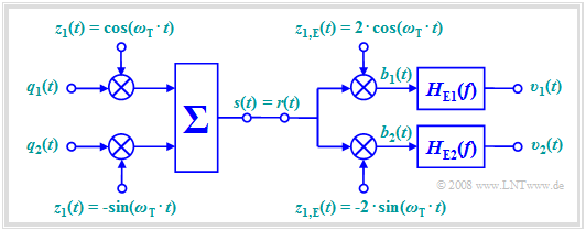
By exploiting the orthogonality of cosine and sine functions, a channel can be used twice for simultaneous transmission of two source signals $q_1(t)$ and $q_2(t)$ without mutual interference. This method is called "quadrature amplitude modulation" $\rm (QAM)$.
The QAM system has the following characteristics:
- The transmitted signal is composed of two mutually orthogonal components:
- $$s(t) = q_1(t) \cdot \cos (\omega_{\rm T}\cdot t) - q_2(t) \cdot \sin (\omega_{\rm T}\cdot t)\hspace{0.05cm}.$$
- For frequency and phase synchronous demodulation, the signal in the upper branch before the low-pass $H_{\rm E1}(f)$ is:
- $$b_1(t) = q_1(t) \cdot 2 \cdot \cos^2 (\omega_{\rm T}\cdot t) - q_2(t) \cdot 2 \cdot \cos (\omega_{\rm T}\cdot t)\cdot \sin (\omega_{\rm T}\cdot t) $$
- $$\Rightarrow \hspace{0.3cm} b_1(t) = q_1(t)\cdot \big[ 1 + \cos (2 \omega_{\rm T}\cdot t) \big] - q_2(t)\cdot \sin (2 \omega_{\rm T}\cdot t) \hspace{0.05cm}.$$
- Thus, by limiting to frequencies $|f| < f_{\rm T}$, we obtain in the upper and lower branches, resp.:
- $$v_1(t) = q_1(t),$$
- $$v_2(t) = q_2(t)\hspace{0.05cm}.$$
- When there is a phase offset $Δϕ_{\rm T}$ between the transmitted and received carrier signals, in addition to attenuation of the intended participant,
crosstalk from the second participant occurs, resulting in nonlinear distortion:
- $$v_1(t) = \alpha_{11} \cdot q_1(t)+ \alpha_{12} \cdot q_2(t) \hspace{0.05cm}, $$
- $$v_2(t) = \alpha_{21} \cdot q_1(t)+ \alpha_{22} \cdot q_2(t)$$
- $$\Rightarrow\hspace{0.3cm}\alpha_{11} = \alpha_{22} = \cos(\Delta \phi_{\rm T}) \hspace{0.05cm}, \hspace{0.3cm} \alpha_{12} = -\alpha_{21} = \sin(\Delta \phi_{\rm T}) \hspace{0.05cm}.$$
Incoherent (non-coherent) Demodulation
$\text{Definition:}$ Demodulators can be classified in the following way:
- A demodulator is said to be »coherent«, if in addition to the required frequency synchronization, it requires accurate information about the phase of the transmit-side carrier signal $z(t)$ to reconstruct the source signal.
- If this phase information is not required, the demodulator is said to be an »incoherent demodulator« or "non-coherent demodulator".
An example of an incoherent demodulator is the $\text{envelope demodulator}$.
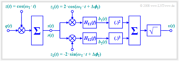
$\text{Example 2:}$ A second example is shown in the following block diagram. In contrast to quadrature amplitude modulation, here the orthogonality between cosine and sine functions is not used for the simultaneous transmission of a second source signal, but rather to simplify the receiver-side device.
It should be further noted regarding this arrangement:
- The receiver-side carrier signals can have an arbitrary and also time-dependent phase offset $Δϕ_{\rm T}$ with respect to the carrier signals at the transmitter, as long as the phase difference between the two branches remains exactly $90^\circ$ .
- For the signals in the upper and lower branches – after the multiplier and low-pass filtering, respectively – it holds:
- $$b_1(t) = \cos(\Delta \phi_{\rm T}) \cdot q(t), $$
- $$b_2(t) = -\sin(\Delta \phi_{\rm T}) \cdot q(t).$$
- This ensures that the sink signal $v(t)$ matches the source signal $q(t)$ in magnitude, regardless of the phase offset $Δϕ_{\rm T}$:
- $$v(t) = \sqrt{ b_1^2(t) + b_2^2(t)} = \sqrt{ q^2(t) } = \vert q(t) \vert \hspace{0.05cm}.$$
- A prerequisite for operability – that is, for the result $v(t) = q(t)$ – is that at all times $q(t) ≥ 0$. In an analog transmission system, this fact could be enforced using the "DSB-AM with carrier" modulation method, for example.
- This form of non-coherent demodulation (or modifications of it) is mainly applied in some »digital modulation methods«, which are discussed in detail in the fourth chapter of "this book".
Exercises for the chapter
Exercise 2.12: Non-coherent Demodulation
Exercise 2.13: Quadrature Amplitude Modulation (QAM)
References
- ↑ Mäusl, R.: Analoge Modulationsverfahren. Heidelberg: Dr. Hüthig, 1988.


