Difference between revisions of "Modulation Methods/Quadrature Amplitude Modulation"
m |
m |
||
| Line 110: | Line 110: | ||
==Error probabilities of 4–QAM== | ==Error probabilities of 4–QAM== | ||
<br> | <br> | ||
| − | + | In the earlier section [[Modulation_Methods/Linear_Digital_Modulation#Error_probabilities_-_a_brief_overview|Error probabilities – a brief overview]] , the bit error probability of ''binary phase shift keying'' $\rm BPSK)$ was given, among other things. Now the results are transferred to $\text{4-QAM}$ , where the following conditions still apply: | |
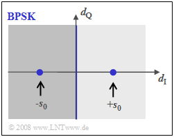
| − | [[File:P_ID1717__Mod_T_4_3_S5a_ganz_neu.png|right|frame| | + | [[File:P_ID1717__Mod_T_4_3_S5a_ganz_neu.png|right|frame|Phase diagram of $\rm BPSK$]] |
| − | * | + | *a transmit signal with the average energy $E_{\rm B}$ per bit, |
| − | * | + | *AWGN noise with the (single-sided) noise power density $N_0$, |
| − | * | + | *the best possible receiver realization using the matched-filter principle. |
| − | + | The upper image shows the BPSK phase diagram of the detection signal $d(t)$, i.e., including the matched filter. The distance of the useful signal from the threshold ($d_{\rm Q}$–axis) is $s_0$ at each of the detection times. | |
| − | + | Using the additional equations | |
:$$p_{\rm B} = {\rm Q}\left ( {s_0}/{\sigma_d } \right ), \hspace{0.2cm} E_{\rm B} = {1}/{2} \cdot s_0^2 \cdot T_{\rm B} ,\hspace{0.2cm} \sigma_d^2 = {N_0}/{T_{\rm B} }$$ | :$$p_{\rm B} = {\rm Q}\left ( {s_0}/{\sigma_d } \right ), \hspace{0.2cm} E_{\rm B} = {1}/{2} \cdot s_0^2 \cdot T_{\rm B} ,\hspace{0.2cm} \sigma_d^2 = {N_0}/{T_{\rm B} }$$ | ||
| − | + | the '''BPSK error probability''' is given by: | |
$$p_{\rm B, \hspace{0.1cm}BPSK} = {\rm Q}\left ( \sqrt{{2 \cdot E_{\rm B}}/{N_0 }} \hspace{0.1cm}\right ) = {1}/{2}\cdot {\rm erfc}\left ( \sqrt{{E_{\rm B}}/{N_0 }} \hspace{0.1cm}\right ).$$ | $$p_{\rm B, \hspace{0.1cm}BPSK} = {\rm Q}\left ( \sqrt{{2 \cdot E_{\rm B}}/{N_0 }} \hspace{0.1cm}\right ) = {1}/{2}\cdot {\rm erfc}\left ( \sqrt{{E_{\rm B}}/{N_0 }} \hspace{0.1cm}\right ).$$ | ||
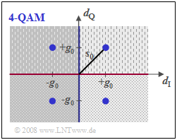
| − | [[File: P_ID2965__Mod_T_4_3_S5b_neu.png|right|frame| | + | [[File: P_ID2965__Mod_T_4_3_S5b_neu.png|right|frame|Phase diagram of $\text{4-QAM}$]] |
| − | + | In the $\text{4-QAM}$ corresponding to the image below | |
| − | * | + | *there are two thresholds between the areas with lighter/darker background (blue line) and between the dotted/dashed areas (red line), |
| − | * | + | *the distance from each threshold is only $g_0$ instead of $s_0$, |
| − | * | + | *but the noise power $\sigma_d^2$ is also only half as large compared to BPSK because of the halved symbol rate in each sub-branch. |
| − | + | Thus, with the equations | |
:$$p_{\rm B} = {\rm Q}\left ( {g_0}/{\sigma_d } \right ), \hspace{0.2cm}g_{0} = {s_0}/{\sqrt{2}}, \hspace{0.2cm}E_{\rm B} = {1}/{2} \cdot s_0^2 \cdot T_{\rm B} ,\hspace{0.2cm} | :$$p_{\rm B} = {\rm Q}\left ( {g_0}/{\sigma_d } \right ), \hspace{0.2cm}g_{0} = {s_0}/{\sqrt{2}}, \hspace{0.2cm}E_{\rm B} = {1}/{2} \cdot s_0^2 \cdot T_{\rm B} ,\hspace{0.2cm} | ||
\sigma_d^2 = {N_0}(2 \cdot T_{\rm B} )$$ | \sigma_d^2 = {N_0}(2 \cdot T_{\rm B} )$$ | ||
| − | + | one obtains the exact same result for the '''4-QAM error probability''' as for $\text{BPSK}$: | |
:$$p_{\rm B, \hspace{0.1cm}4-QAM} = {\rm Q}\left ( \sqrt{{2 \cdot E_{\rm B}}/{N_0 }} \hspace{0.1cm}\right ) = {1}/{2}\cdot {\rm erfc}\left ( \sqrt{{E_{\rm B}}/{N_0 }} \hspace{0.1cm}\right ).$$ | :$$p_{\rm B, \hspace{0.1cm}4-QAM} = {\rm Q}\left ( \sqrt{{2 \cdot E_{\rm B}}/{N_0 }} \hspace{0.1cm}\right ) = {1}/{2}\cdot {\rm erfc}\left ( \sqrt{{E_{\rm B}}/{N_0 }} \hspace{0.1cm}\right ).$$ | ||
{{BlaueBox|TEXT= | {{BlaueBox|TEXT= | ||
| − | $\text{ | + | $\text{Conclusion:}$ |
| − | * | + | *Under ideal conditions, $\text{4-QAM}$ has the same error probability as $\text{BPSK}$, although twice the amount of information can be transmitted. |
| − | * | + | *However, if the conditions are no longer ideal - for example, if there is an unwanted phase offset between the transmitter and receiver - there is much more degradation with 4-QAM than with BPSK. |
| − | *Dieser Fall wird im Abschnitt [[Digital_Signal_Transmission/ | + | *Dieser Fall wird im Abschnitt [[Digital_Signal_Transmission/Linear_Digital_Modulation_-_Coherent_Demodulation#Error_probabilities_for_4.E2.80.93QAM_and_4.E2.80.93PSK|Error probabilities for 4–QAM and 4–PSK]] des Buches „Digitalsignalübertragung” noch genauer betrachtet. }} |
==Quadratische QAM–Signalraumkonstellationen== | ==Quadratische QAM–Signalraumkonstellationen== | ||
Revision as of 16:31, 18 March 2022
Contents
- 1 General description and signal space allocation
- 2 System description using the equivalent low-pass signal
- 3 Power and energy of QAM Signals
- 4 Signal waveforms for 4–QAM
- 5 Error probabilities of 4–QAM
- 6 Quadratische QAM–Signalraumkonstellationen
- 7 Other signal space constellations
- 8 Nyquist– und Wurzel–Nyquist–QAM–Systeme
- 9 Offset–Quadraturamplitudenmodulation
- 10 Aufgaben zum Kapitel
- 11 Quellenverzeichnis
General description and signal space allocation
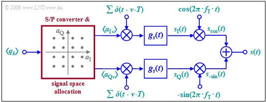
Due to the orthogonality of cosine and (minus) sine, two data streams can be transmitted independently via the same transmission channel. The diagram shows the general circuit schematic.
This very general model can be described as follows:
- The binary source symbol sequence $〈q_k〉$ with bit rate $R_{\rm B}$ is applied to the input. Thus, the time interval between two symbols is $T_{\rm B} = 1/R_{\rm B}$.
- Two multilevel amplitude coefficients $a_{{\rm I}ν}$ and $a_{{\rm Q}ν}$ are derived from each $b$ binary input symbols $q_k$ , where $\rm I$ stands for inphase and $\rm Q$ stands for quadrature component.
- If $b$ is even and the signal space allocation is quadratic, then the coefficients $a_{{\rm I}ν}$ and $a_{{\rm Q}ν}$ can each take on one of the $M = 2^{b/2}$ amplitude values with equal probability. This is then referred to as quadrature amplitude modulation $\rm (QAM)$.
- The example considered in the graph is for $\text{16-QAM}$ with $b = M = 4$ and correspondingly $M^2 =16$ signal space points. For a $\text{256-QAM}$ , $b = 8$ and $M = 16$ would apply: $2^b = M^2 = 256$.
- Next, the coefficients $a_{{\rm I}ν}$ and $a_{{\rm Q}ν}$ are each applied to a Dirac impulse as pulse weights. Thus, after shaping a pulse with the fundamental transmission pulse $g_s(t)$ , the following holds for both branches of the circuit diagram:
- $$s_{\rm I}(t) = \sum_{\nu = - \infty}^{+\infty}a_{\rm I\hspace{0.03cm}\it \nu} \cdot g_s (t - \nu \cdot T)\hspace{0.05cm},\hspace{1cm}s_{\rm Q}(t) = \sum_{\nu = - \infty}^{+\infty}a_{\rm Q\hspace{0.03cm}\it \nu} \cdot g_s (t - \nu \cdot T)\hspace{0.05cm}.$$
- Note that because of the redundancy-free conversion, the symbol duration $T$ of these signals is larger by a factor of $b$ than the bit duration $T_{\rm B}$ of the binary source signal. In the illustrated example $\text{(16-QAM)}$ , $T = 4 · T_{\rm B}$ holds.
- The QAM transmitted signal $s(t)$ is then the sum of the two signals multiplied by cosine and minus-sine, respectively:
- $$s_{\rm cos}(t) = s_{\rm I}(t) \cdot \cos(2 \pi f_{\rm T} t), \hspace{1cm} s_{\rm -sin}(t) = -s_{\rm Q}(t) \cdot \sin(2 \pi f_{\rm T} t)$$
- $$\Rightarrow \hspace{0.3cm}s(t) = s_{\rm cos}(t)+ s_{\rm -sin}(t) = s_{\rm I}(t) \cdot \cos(2 \pi f_{\rm T} t) - s_{\rm Q}(t) \cdot \sin(2 \pi f_{\rm T} t) \hspace{0.05cm}.$$
$\text{Conclusion:}$ these statements can be summarized as follows:
- The two transmission branches $\rm (I,\ Q)$ can be thought of as two completely separate $M$-step ASK systems that do not interfere with each other as long as all components are optimally designed.
- Quadrature amplitude modulation thus makes it (ideally) possible to double the data rate while maintaining the same quality.
System description using the equivalent low-pass signal
Since the multiplication of $s_{\rm I}(t)$ and $s_{\rm Q}(t)$ , with a cosine and minus-sine oscillation respectively, only causes a shift in the frequency domain and such a shift is a linear operation, the system description can be greatly simplified using the equivalent low-pass signals.
- The graph shows the simplified model in the baseband. This is equivalent to the block diagram considered so far.
- The serial-parallel conversion and the signal space allocation drawn in red in the block diagram are retained. This block is no longer drawn here.
- We also initially disregard the bandpass $H_{\rm BP}(f)$ , which is often introduced for technical reasons.
Please note the following:
- All double arrows in the baseband model denote complex quantities. The operations associated with them should also be understood as complex. For example, the complex amplitude coefficient $a_ν$  combines one inphase and one quadrature coefficient:
- $$a_\nu = a_{\rm I\hspace{0.03cm}\it \nu} + {\rm j} \cdot a_{\rm Q\hspace{0.03cm}\it \nu} \hspace{0.05cm}.$$
- The equivalent low-pass representation of the actual, physical and thus per se real transmitted signal $s(t)$ is always complex in QAM and with the partial signals $s_{\rm I}(t)$ and $s_{\rm Q}(t)$ it holds that:
- $$s_{\rm TP}(t) = s_{\rm I}(t) + {\rm j} \cdot s_{\rm Q}(t) = \sum_{\nu = - \infty}^{+\infty} a_\nu \cdot g_s (t - \nu \cdot T)\hspace{0.05cm}.$$
- The analytical signal $s_+(t)$ is obtained from $s_{\rm TP}(t)$ by multiplying by the complex exponential function. The physical transmitted signal $s(t)$ ) is then obtained as the real part of $s_+(t)$.
- In order for the signs in the block diagram on the previous page and the sketched baseband model to match, multiplication by the negative sine wave is required in the quadrature branch, as shown in the following calculation:
- $$s(t) = {\rm Re}[s_{\rm +}(t)] = {\rm Re}[s_{\rm TP}(t) \cdot{\rm e}^{{\rm j}2\pi f_{\rm T} t}] $$
- $$\Rightarrow \hspace{0.3cm} s(t) = {\rm Re} \left[\left ( \sum (a_{\rm I\hspace{0.03cm}\it \nu} + {\rm j} \cdot a_{\rm Q\hspace{0.03cm}\it \nu} ) \cdot g_s (t - \nu \cdot T)\right )\left ( \cos(2 \pi f_{\rm T} t) + {\rm j} \cdot \sin(2 \pi f_{\rm T} t) \right )\right]= s_{\rm I}(t) \cdot \cos(2\pi f_{\rm T} t) - s_{\rm Q}(t) \cdot \sin(2 \pi f_{\rm T} t) \hspace{0.05cm}.$$
- The influence of the bandpass $H_{\rm BP}(f)$, which in practice often has to be considered at the output of the QAM modulator, can be assigned to the pulse shape filter $g_s(t)$ . If the passband of the bandpass filter is symmetric about $f_{\rm T}$, its low-pass equivalent (in the time domain) $h_{\rm BP→TP}(t)$ is purely real and one can replace $g_s(t)$ with $g_s(t) \star h_{\rm BP→TP}(t)$ in the model.
Power and energy of QAM Signals
As shown in the chapter Equivalent Low-Pass Signal and its Spectral Function in the book "Signal Representation", the power of the transmitted QAM signal $s(t)$ can also be calculated from the equivalent low-pass signal $s_{\rm TP}(t)$ , which is always complex. Thus, it is equally valid to write:
- $$P = \lim_{T_{\rm M} \rightarrow \infty} \frac{\rm 1}{T_{\rm M}}\cdot \int_{-T_{\rm M}/2}^{+T_{\rm M}/2} s^2(t)\,{\rm d} t = {\rm 1}/{2} \cdot \lim_{T_{\rm M} \rightarrow \infty} \frac{\rm 1}{T_{\rm M}}\cdot \int_{-T_{\rm M}/2}^{+T_{\rm M}/2} |s_{\rm TP}(t)|^2\,{\rm d} t \hspace{0.05cm}.$$
In contrast, the energy of the unbounded signals $s(t)$ and $s_{\rm TP}(t)$ is infinite.
However, if we restrict ourselves to a symbol duration $T$, we obtain the energy per symbol:
- $$E_{\rm S} = \frac{{\rm E}[\hspace{0.05cm}|a_{\nu} |^2\hspace{0.05cm}]}{2}\cdot \int_{-\infty}^{+\infty} |g_s(t)|^2\,{\rm d} t = \frac{{\rm E}[|a_{\nu} |^2]}{2}\cdot \int_{-\infty}^{+\infty} |G_s(f)|^2\,{\rm d} f \hspace{0.05cm}.$$
On the other hand, $E_{\rm B} = E_{\rm S}/b$ gives the energy per bit when each binary symbol $b$ is combined to form the complex coefficient $a_\nu$ according to the signal space allocation.
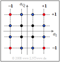
$\text{Example 1:}$ the top graph shows the signal space allocationfor $\text{16-QAM}$, where both the real and imaginary parts of the complex amplitude coefficients $a_ν$ can take one of four values $±1$ as well as $±1/3$ , respectively.
Averaging over the $16$ squared distances to the origin yields:
- $${\rm E}\big[\hspace{0.05cm} \vert a_{\nu}\vert^2 \hspace{0.05cm}\big] \hspace{0.18cm} = \hspace{0.18cm} \frac{4}{16} \cdot (1^2 + 1^2)+ \frac{4}{16} \cdot \left[(1/3 )^2 +(1/3)^2 \right ] + \frac{8}{16} \cdot \left [1^2 + (1/3)^2\right ] $$
- $$\Rightarrow \hspace{0.3cm}{\rm E}\big[\hspace{0.05cm} \vert a_{\nu}\vert^2 \hspace{0.05cm}\big] = {10}/{9}\approx 1.11 \hspace{0.05cm}.$$
In this order, the summands belong to
- the four red,
- the four black, and
- the eight blue dots.
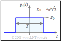
For a NRZ rectangular fundamental transmit pulse $g_s(t)$ with amplitude $g_0$ and symbol duration $T$ , the spectrum $G_s(f)$ is $\rm si$–shaped.
In this case, the following holds true for
- the average energy per symbol:
- $$E_{\rm S} = 1/2 \cdot {\rm E}\big[\hspace{0.05cm}\vert a_{\nu} \vert ^2 \big]\hspace{0.05cm}\cdot g_0^2 \cdot T = {5}/{9}\cdot g_0^2 \cdot T \hspace{0.05cm}\approx 0.555 \cdot g_0^2 \cdot T \hspace{0.05cm},$$
- the average energy per bit:
- $$E_{\rm B} ={E_{\rm S} }/{4}= {5}/{36}\cdot g_0^2 \cdot T \approx 0.139 \cdot g_0^2 \cdot T \hspace{0.05cm}.$$
The "maximum envelope" $s_0$ of the transmitted signal $s(t)$ is larger than the amplitude $g_0$ of the rectangular pulse by a factor of $\sqrt{2}$ (see bottom sketch) and occurs at one of the four red amplitude coefficients, i.e., whenever $\vert a_{\rm I \it ν}\vert = \vert a_{\rm Q \it ν}\vert =1$ .
Signal waveforms for 4–QAM
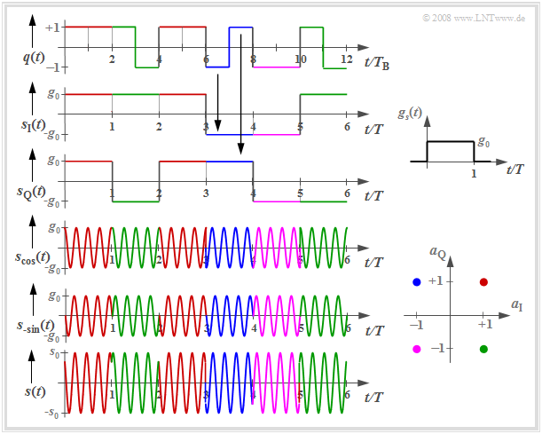
The following graph shows the signal waveforms of $\rm 4-QAM$, where the coloring corresponds to the signal space allocation defined above.
One can see from these plots:
- the serial-to-parallel conversion of the source signal $q(t)$ into the two component signals 𝑠 $s_{\rm I}(t)$ and $s_{\rm Q}(t)$, each with symbol duration $T = 2T_{\rm B}$ and signal values $±g_0$. Here, $T_{\rm B}$ denotes the bit duration;
- the two carrier frequency modulated signals $s_{\rm cos}(t)$ and $s_{\rm –sin}(t)$ with phase jumps around $±π$:
- $$s_{\rm cos} (t) = s_{\rm I} (t) \cdot \cos(2\pi f_{\rm T}t)\hspace{0.05cm},$$
- $$s_{\rm -sin} (t) = -s_{\rm Q} (t) \cdot \sin(2\pi f_{\rm T}t)\hspace{0.05cm}, $$
- the transmitted signal $s(t) = s_{\rm cos}(t) \ – \ s_{\rm –sin}(t)$ with phase jumps by multiples of $±π/2$;; their envelope is larger than the two component signals by a factor of $\sqrt{2}$ :
- $$s_0 = \sqrt{2} \cdot g_0 \hspace{0.05cm}.$$
- Here, fundamental transmission pulse $g_s(t)$ is assumed to be rectangular between $0$ and $T$ , i.e., asymmetric with respect to $t = 0$, for simplicity of representation.
- The associated spectral function $G_s(f)$ of this causal pulse $g_s(t)$ is complex, though this has no implications in this context.
Error probabilities of 4–QAM
In the earlier section Error probabilities – a brief overview , the bit error probability of binary phase shift keying $\rm BPSK)$ was given, among other things. Now the results are transferred to $\text{4-QAM}$ , where the following conditions still apply:
- a transmit signal with the average energy $E_{\rm B}$ per bit,
- AWGN noise with the (single-sided) noise power density $N_0$,
- the best possible receiver realization using the matched-filter principle.
The upper image shows the BPSK phase diagram of the detection signal $d(t)$, i.e., including the matched filter. The distance of the useful signal from the threshold ($d_{\rm Q}$–axis) is $s_0$ at each of the detection times.
Using the additional equations
- $$p_{\rm B} = {\rm Q}\left ( {s_0}/{\sigma_d } \right ), \hspace{0.2cm} E_{\rm B} = {1}/{2} \cdot s_0^2 \cdot T_{\rm B} ,\hspace{0.2cm} \sigma_d^2 = {N_0}/{T_{\rm B} }$$
the BPSK error probability is given by: $$p_{\rm B, \hspace{0.1cm}BPSK} = {\rm Q}\left ( \sqrt{{2 \cdot E_{\rm B}}/{N_0 }} \hspace{0.1cm}\right ) = {1}/{2}\cdot {\rm erfc}\left ( \sqrt{{E_{\rm B}}/{N_0 }} \hspace{0.1cm}\right ).$$
In the $\text{4-QAM}$ corresponding to the image below
- there are two thresholds between the areas with lighter/darker background (blue line) and between the dotted/dashed areas (red line),
- the distance from each threshold is only $g_0$ instead of $s_0$,
- but the noise power $\sigma_d^2$ is also only half as large compared to BPSK because of the halved symbol rate in each sub-branch.
Thus, with the equations
- $$p_{\rm B} = {\rm Q}\left ( {g_0}/{\sigma_d } \right ), \hspace{0.2cm}g_{0} = {s_0}/{\sqrt{2}}, \hspace{0.2cm}E_{\rm B} = {1}/{2} \cdot s_0^2 \cdot T_{\rm B} ,\hspace{0.2cm} \sigma_d^2 = {N_0}(2 \cdot T_{\rm B} )$$
one obtains the exact same result for the 4-QAM error probability as for $\text{BPSK}$:
- $$p_{\rm B, \hspace{0.1cm}4-QAM} = {\rm Q}\left ( \sqrt{{2 \cdot E_{\rm B}}/{N_0 }} \hspace{0.1cm}\right ) = {1}/{2}\cdot {\rm erfc}\left ( \sqrt{{E_{\rm B}}/{N_0 }} \hspace{0.1cm}\right ).$$
$\text{Conclusion:}$
- Under ideal conditions, $\text{4-QAM}$ has the same error probability as $\text{BPSK}$, although twice the amount of information can be transmitted.
- However, if the conditions are no longer ideal - for example, if there is an unwanted phase offset between the transmitter and receiver - there is much more degradation with 4-QAM than with BPSK.
- Dieser Fall wird im Abschnitt Error probabilities for 4–QAM and 4–PSK des Buches „Digitalsignalübertragung” noch genauer betrachtet.
Quadratische QAM–Signalraumkonstellationen
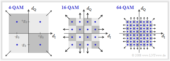
Die folgende Grafik zeigt die Signalraumkonstellationen von $\text{4-QAM}$, $\text{16-QAM}$ und $\text{64-QAM}$.
- Mit den hier gewählten Achsenbeschriftungen beschreiben die Bilder auch das Detektionsnutzsignal (zu den Detektionszeitpunkten) im äquivalenten Tiefpassbereich.
- Ebenfalls eingezeichnet sind die verschiedenen Entscheidungsgebiete, die dem verrauschten Detektionssignal zugeordnet werden.
- Die Pfeile geben an, wenn Entscheidungsgebiete bis ins Unendliche ausgedehnt sind.
Die Bilder beziehen sich nur auf die Detektionszeitpunkte und gelten für alle Nyquistsysteme
- wie die Rechteck–Rechteck–Konfiguration (Sendegrundimpuls und Empfangsfilter–Impulsantwort seien rechteckförmig)
- oder ein Wurzel–Cosinus–Rolloff–Nyquistsystem.
Die hier nicht dargestellten Übergänge zwischen den einzelnen Punkten (außerhalb der Detektionszeitpunkte) hängen aber sehr wohl vom gewählten Nyquistsystem ab.
Weiter ist zu diesen Darstellungen anzumerken:
- Bei echter QAM–Struktur – das heißt: die Signalraumkonstellation ist quadratisch oder zumindest rechteckförmig – lässt sich die „zweidimensionale” Detektion durch zwei „eindimensionale” Detektionsvorgänge vereinfacht lösen.
- Die $\text{16-QAM}$ ist somit nichts anderes als die parallele Übertragung zweier Digitalsignale mit jeweils $M = 4$ Amplitudenstufen.
- Bei der $\text{64-QAM}$ würde entsprechend $M = 8$ gelten und bei der $\text{256-QAM}$ ist die „eindimensionale” Stufenzahl $M = 16$.
- Alle im Kapitel Redundanzfreie Codierung des Buches "Digitalsignalübertragung" genannten Eigenschaften für redundanzfreie mehrstufige Signale gelten auch hier, wobei allerdings die Zusetzung der orthogoalen Trägerfrequenzsignale noch geeignet zu berücksichtigen ist.
Other signal space constellations
Die Grafik zeigt weitere Signalraumkonstellationen. Links ist die 4–QAM nach der bisherigen Beschreibung dargestellt. Die Konstellation rechts daneben kennzeichnet eine vierstufige Phasenmodulation, die wir "4–PSK" bzw. "QPSK" nennen. Ein Vergleich dieser beiden linken Diagramme zeigt:
- Die hier als QPSK (Quaternary Phase Shift Keying ) bezeichnete Variante verwendet die Phasenlagen $0^\circ$, $90^\circ$, $180^\circ$ und $270^\circ$.
- Aus den eingezeichneten Entscheidungsgebieten erkennt man, dass hier die Detektion nicht auf zwei Binärentscheidungen zurückgeführt werden kann.
- Auch die 4–QAM (links) kann als vierstufige Phasenmodulation aufgefasst werden $($Phasenlagen $±45^\circ$, $±135^\circ)$.
- Gegenüber der QPSK ergibt sich eine Drehung um $±45^\circ$ $(π/4)$ ⇒ die 4–QAM oft auch als ${\rm π/4}\text{–QPSK}$ bezeichnet.
- Ähnlich wie man bei der BPSK durch Vorcodierung zur DPSK kommt, kann auch die 4–PSK zur 4–DPSK erweitert und dadurch die Demodulation erleichtert werden.
- Diese wurde zum Beispiel bei der Datenübertragung über Telefonkanäle gemäß CCITT–Empfehlung "V26" angewendet $($Trägerfrequenz $\text{1800 Hz}$, Datenrate $\text{2400 bit/s)}$.
Die beiden rechten Diagramme zeigen höherstufige Modulationsverfahren:
- Die 8–PSK (bzw. 8–DPSK) erlaubt entsprechend der CCITT–Empfehlung "V27" beim Telefonkanal eine Datenrate von bis zu $\text{4800 bit/s}$.
- Die Empfehlung "V29" sieht mit der 16–ASK/PSK eine hybride Modulationsform vor, die bei fest verschalteten Leitungen Datenraten bis $\text{9600 bit/s}$ ermöglicht.
Nyquist– und Wurzel–Nyquist–QAM–Systeme
Bisher wurde in diesem Kapitel aus Darstellungsgründen stets vom rechteckförmigen Sendegrundimpuls ausgegangen. In der Praxis verwendet man aber meist eine Wurzel–Nyquist–Charakteristik entsprechend der Beschreibung im Buch "Digitalsignalübertragung". In aller Kürze lassen sich diese Systeme wie folgt charakterisieren:
- Der Empfängerfrequenzgang $H_{\rm E}(f)$ wird hier formgleich mit dem (normierten) Sendeimpulsspektrum $H_{\rm S}(f)$ gewählt, was unter der Nebenbedingung der Leistungsbegrenzung (das heißt: bei konstanter mittlerer Sendeleistung) zur kleinstmöglichen Fehlerwahrscheinlichkeit führt.
- Der Gesamtfrequenzgang $H_{\rm Nyq}(f) = H_{\rm S}(f) · H_{\rm E}(f)$ erfüllt das erste Nyquistkriterium, so dass es beim Empfänger zu keinen Impulsinterferenzen kommt. $H_{\rm S}(f)$ und $H_{\rm E}(f)$ haben somit jeweils eine Wurzel–Nyquist–Charakteristik.
- Für den Frequenzgang $H_{\rm Nyq}(f)$ verwendet man einen Cosinus–Rolloff–Tiefpass $H_{\rm CRO}(f)$ mit der äquivalenten Bandbreite $Δf_{\rm CRO} = 1/T$ und frei wählbarem Rolloff–Faktor $(0 ≤ r ≤ 1)$. Das interaktive Applet Frequenzgang und Impulsantwort verdeutlicht den Frequenzgang und die Impulsantwort dieses Tiefpasses.
- Der Vorteil dieser Wurzel–Nyquist–Systeme ist die deutlich kleinere Bandbreite $(1 + r)/T$ gegenüber der bisher betrachteten Konfiguration mit rechteckförmigem $g_s(t)$ und rechteckförmigem $h_{\rm E}(t)$, dessen Spektrum (theoretisch) unendlich weit ausgedehnt ist.
- Hinsichtlich Fehlerwahrscheinlichkeit ändert sich gegenüber der Rechteck–Rechteck–Konfiguration nichts, da der Grundimpuls $g_d(t)$ vor dem Entscheider äquidistante Nulldurchgänge aufweist und somit Impulsinterferenzen vermieden werden.
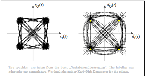
Die Grafik zeigt Phasendiagramme für diesen Fall, die dem Buch [Kam04][1] entnommen sind. Der Rolloff–Faktor beträgt $r = 0.5$. Man erkennt aus diesen Darstellungen:
- Das rechte Diagramm zeigt die Detektionssignale im $\rm I$– und $\rm Q$–Zweig nach den Wurzel–Nyquist–Empfangsfiltern in 2D–Darstellung. Die dazugehörigen Spektren besitzen jeweils cosinusförmige Flanken um die Nyquistfrequenz $f_{\rm Nyq} = 1/(2T)$.
- Zu den Detektionszeitpunkten sind im Phasendiagramm nur die vier gelb eingezeichneten Punkte möglich. Die Übergänge dazwischen sind vielfältig. Anzumerken ist, dass nur wenige Linien durch den Koordinaten-Nullpunkt gehen.
- Links dargestellt sind die beiden Sendesignale im äquivalenten Tiefpassbereich, $s_{\rm I}(t) = {\rm Re}\big[s_{\rm TP}(t)\big]$ und $s_{\rm Q}(t) = {\rm Im}\big[s_{\rm TP}(t)\big]$. Aufgrund der Wurzel–Nyquist–Spektralformung gibt es beim Sender Impulsinterferenzen, das heißt, dass das äquivalente Tiefpass–Signal $s_{\rm TP}(t) = s_{\rm I}(t) + {\rm j} · s_{\rm Q}(t)$ auch zu den Detektionszeitpunkten nicht auf vier Punkte beschränkt ist.
- Der Betrag $|s_{\rm TP}(t)|$ – also der Abstand vom Nullpunkt – gibt die Hüllkurve des 4–QAM–Signals an. Man erkennt aus dem linken Diagramm deutlich, dass es insbesondere bei Phasenänderungen um $π$ starke Amplitudeneinbrüche gibt, da $s_{\rm TP}(t)$ dann häufig auch (komplexe) Werte nahe Null annimmt.
Offset–Quadraturamplitudenmodulation
Ausgehend von den Gleichungen für die $\text{4–QAM}$ $($bzw. $π/4\text{–QPSK)}$ kommt man zur $\text{Offset–4–QAM}$, die wir vereinfachend mit $\text{Offset–QPSK}$ bezeichnen. Für das Sendesignal gilt hier:
- $$s(t) =s_{\rm I}(t) \cdot \cos(2 \pi f_{\rm T} t) - s_{\rm Q}(t) \cdot \sin(2 \pi f_{\rm T} t),$$
- $$\hspace{0.3cm}\Rightarrow \hspace{0.3cm}s_{\rm I}(t) = \sum_{\nu = - \infty}^{+\infty}a_{\rm I\hspace{0.03cm}\it \nu} \cdot g_s (t - \nu \cdot T)\hspace{0.05cm},\hspace{0.5cm} s_{\rm Q}(t) = \sum_{\nu = - \infty}^{+\infty}a_{\rm Q\hspace{0.03cm}\it \nu} \cdot g_s (t -{T}/{2} - \nu \cdot T)\hspace{0.05cm}.$$
Der einzige, aber entscheidende Unterschied ist die zeitliche Verschiebung der Quadraturkomponente gegenüber der Inphasekomponente um eine halbe Symboldauer $(T/2)$. Dies hat den Vorteil, dass
- die Phasenfunktion nicht durch Null geht, und
- dadurch die Hüllkurve $|s_{\rm TP}(t)|$ deutlich weniger schwankt.
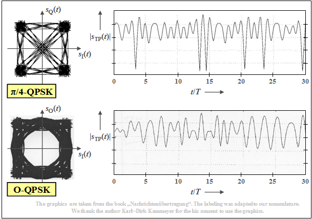
$\text{Beispiel 2:}$ Die obere Grafik zeigt
- links nochmals das Phasendiagramm für die $π/4\hspace{-0.05cm}-\hspace{-0.05cm}\text{QPSK}$,
- rechts daneben einen beispielhaften Verlauf der Hüllkurve, wobei wie im letzten Abschnitt ein Wurzel–Nyquist–Sendespektrum mit dem Rolloff–Faktor $r = 0.5$ zugrunde liegt.
Die unteren Bilder zeigen, dass die $\text{Offset – QPSK}$ hinsichtlich der Einhüllenden deutlich bessere Eigenschaften aufweist (weniger gravierende Signaleinbrüche).
Wesentliche Eigenschaften von 4–QAM/QPSK und Offset–QPSK können Sie sich mit dem interaktiven Applet QPSK und Offset-QPSK verdeutlichen, wobei als Grundimpuls alternativ wählbar ist:
- ein Rechteckimpuls,
- ein Cosinusimpuls,
- ein Nyquistimpuls,
- ein Wurzel–Nyquistimpuls.
Aufgaben zum Kapitel
Aufgabe 4.10: Signalverläufe der 16–QAM
Aufgabe 4.10Z: Signalraumkonstellation der 16–QAM
Aufgabe 4.11: Frequenzbereichsbetrachtung der 4–QAM
Aufgabe 4.11Z: Fehlerwahrscheinlichkeit bei QAM
Aufgabe 4.12: Wurzel–Nyquist–Systeme
Aufgabe 4.12Z: Nochmals 4–QAM–Systeme
Quellenverzeichnis
- ↑ Kammeyer, K.D.: Nachrichtenübertragung. Stuttgart: B.G. Teubner, 4. Auflage, 2004.
