Difference between revisions of "Aufgaben:Exercise 4.12: Root-Nyquist Systems"
m |
m |
||
| Line 7: | Line 7: | ||
*In this case, base detection pulse $g_d(t)$ satisfies the [[Digital_Signal_Transmission/Eigenschaften_von_Nyquistsystemen#Erstes_Nyquistkriterium_im_Frequenzbereich|first Nyquist criterion]], since $G_d(f)$ is point-symmetric about the so-called Nyquist frequency $f_{\rm Nyq} = 1/T$ . | *In this case, base detection pulse $g_d(t)$ satisfies the [[Digital_Signal_Transmission/Eigenschaften_von_Nyquistsystemen#Erstes_Nyquistkriterium_im_Frequenzbereich|first Nyquist criterion]], since $G_d(f)$ is point-symmetric about the so-called Nyquist frequency $f_{\rm Nyq} = 1/T$ . | ||
| − | *The spectral function $G_d(f)$ is a [[Linear_and_Time_Invariant_Systems/ | + | *The spectral function $G_d(f)$ is a [[Linear_and_Time_Invariant_Systems/Some_Low-Pass_Functions_in_Systems_Theory#Cosine.E2.80.93square_low-pass_filter|cosine rolloff spectrum]], where the rolloff factor $r$ can take values from $0$ to $1$ (including these limits). |
| Line 28: | Line 28: | ||
Below, the spectrum $G_d(f)$ before the decider is shown in the same colors. | Below, the spectrum $G_d(f)$ before the decider is shown in the same colors. | ||
| − | *The associated impulse $g_d(t)$ is a[[Digital_Signal_Transmission/ | + | *The associated impulse $g_d(t)$ is a [[Digital_Signal_Transmission/Properties_of_Nyquist_Systems#First_Nyquist_criterion_in_the_time_domain|Nyquist impulse]] pulse for all valid rolloff factors $(0 ≤ r ≤ 1)$ as opposed to the fundamental transmission pulse $g_s(t)$. |
*For this, the following equation is given in the literature - for example in '''[Kam04]''' : | *For this, the following equation is given in the literature - for example in '''[Kam04]''' : | ||
:$$g_s(t) = g_0 \cdot \frac{4 r t/T \cdot \cos \left [\pi \cdot (1+r) \cdot t/T \right ]+ \sin \left [\pi \cdot (1-r) \cdot t/T \right ]}{\left [1- (4 r t/T)^2 \right ] \cdot \pi \cdot t/T}\hspace{0.05cm}.$$ | :$$g_s(t) = g_0 \cdot \frac{4 r t/T \cdot \cos \left [\pi \cdot (1+r) \cdot t/T \right ]+ \sin \left [\pi \cdot (1-r) \cdot t/T \right ]}{\left [1- (4 r t/T)^2 \right ] \cdot \pi \cdot t/T}\hspace{0.05cm}.$$ | ||
| Line 43: | Line 43: | ||
''Hints:'' | ''Hints:'' | ||
*This exercise belongs to the chapter [[Modulation_Methods/Quadratur%E2%80%93Amplitudenmodulation|Quadratur–Amplitudenmodulation]]. | *This exercise belongs to the chapter [[Modulation_Methods/Quadratur%E2%80%93Amplitudenmodulation|Quadratur–Amplitudenmodulation]]. | ||
| − | * | + | *Particular reference is made to the page [[Modulation_Methods/Quadrature_Amplitude_Modulation#Nyquist_and_root_Nyquist_QAM_systems|Nyquist and root Nyquist systems]] in this chapter. |
| − | *Further useful informationen can be found in the chapter [[Digital_Signal_Transmission/ | + | *Further useful informationen can be found in the chapter [[Digital_Signal_Transmission/Properties_of_Nyquist_Systems|Properties of Nyquist Systems]] in the book "Digital Signal Transmission". |
| − | * '''[Kam04]''' | + | * '''[Kam04]''' refers to the textbook "Kammeyer, K.D.: Nachrichtenübertragung. Stuttgart: B.G. Teubner, 4. Auflage, 2004". |
| − | * | + | *Energies are to be specified in $\rm V^2s$ ; they thus refer to the reference resistance $R = 1 \ \rm \Omega$. |
| − | === | + | ===Questions=== |
<quiz display=simple> | <quiz display=simple> | ||
| Line 85: | Line 85: | ||
</quiz> | </quiz> | ||
| − | === | + | ===Solution=== |
{{ML-Kopf}} | {{ML-Kopf}} | ||
'''(1)''' Setzt man in die gegebene Gleichung $r = 0$ ein, so verschwinden im Zähler und Nenner die jeweils ersten Terme und man erhält: | '''(1)''' Setzt man in die gegebene Gleichung $r = 0$ ein, so verschwinden im Zähler und Nenner die jeweils ersten Terme und man erhält: | ||
Revision as of 18:23, 19 March 2022
In quadrature amplitude modulation systems, the root-Nyquist variant is often chosen instead of a rectangular basic transmission pulse, which gets its name from the spectral range. The reason for this is the significantly smaller bandwidth.
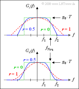
- In this case, base detection pulse $g_d(t)$ satisfies the first Nyquist criterion, since $G_d(f)$ is point-symmetric about the so-called Nyquist frequency $f_{\rm Nyq} = 1/T$ .
- The spectral function $G_d(f)$ is a cosine rolloff spectrum, where the rolloff factor $r$ can take values from $0$ to $1$ (including these limits).
Furthermore, the following holds for the Nyquist frequency response:
- When $|f| < f_1 = f_{\rm Nyq} · (1 – r)$ , $G_d(f)$ is constant and equal to $g_0 · T$.
- At frequencies greater tha $f_2 = f_{\rm Nyq} · (1 + r)$ , $G_d(f)$ has no components.
- In between, the slope is cosine.
The optimization of digital communication systems requires that the receiver frequency response $H_{\rm E}(f)$ should be of the same shape as the transmission spectrum $G_s(f)$ .
To obtain dimensionally correct spectral functions for this task and the graph, it is assumed that:
- $$G_s(f) = \sqrt{g_0 \cdot T \cdot G_d(f)},\hspace{0.4cm} H_{\rm E}(f) = \frac{1}{g_0 \cdot T}\cdot G_s(f)\hspace{0.05cm}.$$
The top graph shows the transmission spectrum $G_s(f)$ for the rolloff factors.
- $r = 0$ (green dotted rectangle),
- $r = 0.5$ (blue solid curve),
- $r = 1$ (red dashed curve).
Below, the spectrum $G_d(f)$ before the decider is shown in the same colors.
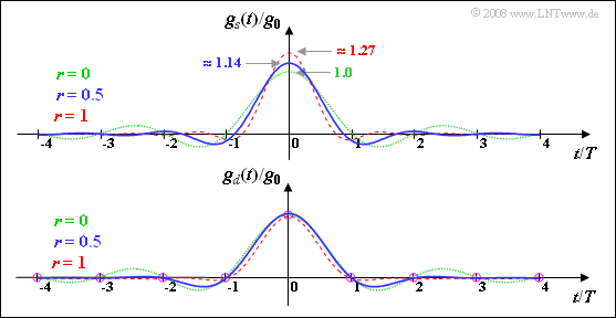
- The associated impulse $g_d(t)$ is a Nyquist impulse pulse for all valid rolloff factors $(0 ≤ r ≤ 1)$ as opposed to the fundamental transmission pulse $g_s(t)$.
- For this, the following equation is given in the literature - for example in [Kam04] :
- $$g_s(t) = g_0 \cdot \frac{4 r t/T \cdot \cos \left [\pi \cdot (1+r) \cdot t/T \right ]+ \sin \left [\pi \cdot (1-r) \cdot t/T \right ]}{\left [1- (4 r t/T)^2 \right ] \cdot \pi \cdot t/T}\hspace{0.05cm}.$$
Hints:
- This exercise belongs to the chapter Quadratur–Amplitudenmodulation.
- Particular reference is made to the page Nyquist and root Nyquist systems in this chapter.
- Further useful informationen can be found in the chapter Properties of Nyquist Systems in the book "Digital Signal Transmission".
- [Kam04] refers to the textbook "Kammeyer, K.D.: Nachrichtenübertragung. Stuttgart: B.G. Teubner, 4. Auflage, 2004".
- Energies are to be specified in $\rm V^2s$ ; they thus refer to the reference resistance $R = 1 \ \rm \Omega$.
Questions
Solution
- $$g_s(t) = g_0 \cdot \frac{\sin \left (\pi \cdot t/T \right )}{\pi \cdot t/T} = g_0 \cdot {\rm si} \left (\pi \cdot {t}/{T} \right )\hspace{0.05cm}.$$
- Zum Zeitpunkt $t = 0$ ist der $\rm si$–Impuls gleich $g_0$:
- $$ g_s(t) \hspace{0.15cm}\underline { = 1.0 } \cdot g_0 \hspace{0.05cm}.$$
(2) Für $r = 1$ lässt sich die angegebene Gleichung wie folgt vereinfachen:
- $$g_s(t) = \frac{4 \cdot g_0}{\pi} \cdot \frac{ \cos \left (2 \pi \cdot t/T \right )}{\left [1- (4 t/T)^2 \right ] }\hspace{0.3cm}\Rightarrow \hspace{0.3cm} g_s(t = 0) = \frac{4 \cdot g_0}{\pi} \hspace{0.15cm}\underline {= 1.273 }\cdot g_0 \hspace{0.05cm}.$$
(3) Richtig ist der letzte Lösungsvorschlag:
- Nulldurchgänge sind für $r = 1$ nur möglich, wenn die Cosinusfunktion im Zähler Null ist, also für alle ganzzahligen Werte von $k$:
- $$2 \pi \cdot t/T = {\pi}/{2} + k \cdot \pi \hspace{0.3cm}\Rightarrow \hspace{0.3cm} t = \pm 0.25T, \hspace{0.15cm} \pm 0.75T, \hspace{0.15cm}\pm 1.25T, \hspace{0.15cm} ...$$
- Richtig ist aber nur der letzte Lösungsvorschlag, da die Nullstellen bei $±0.25T$ durch die Nullstelle im Nenner aufgehoben werden.
- Die Anwendung der Regel von de l'Hospital liefert $g_s(t = ± 0.25T) = g_0$.
(4) Mit $r = 0.5$ und der Abkürzung $x = t/T$ erhält man:
- $$g_s(x) = \frac{g_0}{\pi} \cdot \frac{2 \cdot x \cdot \cos \left (1.5\pi \cdot x \right )+ \sin \left (0.5\pi \cdot x \right )}{\left (1- 4 \cdot x^2 \right ) \cdot x}\hspace{0.05cm}.$$
- Für die Berechnung zum Zeitpunkt $t = 0$ muss die Regel von de l'Hospital angewandt werden.
- Die Ableitungen von Zähler und Nenner ergeben:
- $$Z'(x) = 2 \cdot \cos \left (1.5\pi \cdot x \right ) - 3 \pi \cdot x \cdot \sin \left (1.5\pi \cdot x \right ) + 0.5 \pi \cdot \cos \left (0.5\pi \cdot x \right ),$$
- $$N'(x) = \left (1- 4 \cdot x^2 \right ) - 8 \cdot x^2 \hspace{0.05cm}.$$
- Die beiden Grenzübergänge für $x → 0$ liefern:
- $$\lim_{x \rightarrow 0} Z'(x) = 2 +{\pi }/{2},\hspace{0.2cm} \lim_{x \rightarrow 0} N'(x) = 1 \hspace{0.05cm}.$$
- Damit gilt für die Signalamplitude zum Zeitpunkt $t = 0$:
- $$g_s(t=0) = \frac{g_0}{\pi} \cdot \left ( 2 +{\pi }/{2} \right ) = {g_0} \cdot \left ( 0.5 + {2}/{\pi } \right )\hspace{0.15cm}\underline {= 1.137} \cdot g_0 \hspace{0.05cm}.$$
Die Grafik verdeutlicht nochmals die hier berechneten Ergebnisse:
- Der Impuls $g_d(t)$ ist ein Nyquistimpuls, das heißt, dass er zumindest bei allen Vielfachen der Symboldauer $T$ Nulldurchgänge besitzt (je nach Rolloff–Faktor noch andere Nullstellen).
- Der Impuls $g_s(t)$ erfüllt dagegen nicht die Nyquistbedingung.
- Außerdem erkennt man aus dieser Darstellung nochmals, dass für $r ≠ 0$ die Impulsamplitude $g_s(t = 0)$ stets größer als $g_0$ ist.
(5) Richtig ist der letzte Lösungsvorschlag $($der erste Lösungsvorschlag scheidet bereits nach den Ergebnissen der Teilaufgaben (2) und (4) aus$)$. Die Gültigkeit der unteren Schranke $g_0$ und der oberen Schranke $4g_0/π$ lässt sich wie folgt nachweisen:
- Die Impulsamplitude $g_s(t = 0)$ ist grundsätzlich gleich der Fläche unter der Spektralfunktion $G_s(f)$.
- Die kleinste Fläche ergibt sich für $r = 0$. Hier ist $G_s(f) = g_0 · T$ im Bereich $|f| < ±1/(2T)$. Die Fläche ist somit gleich $g_0$.
- Die größte Fläche ergibt sich für $r = 1$. Hier ist $G_s(f)$ auf den Bereich $±1/T$ ausgedehnt und hat einen cosinusförmigen Verlauf.
- Das Ergebnis $g_s(t = 0) = 4g_0/π$ wurde bereits in Teilaufgabe (3) berechnet. Es gilt aber auch:
- $$g_s(t=0) = 2 \cdot {g_0} \cdot \int_{ 0 }^{1/T} {\cos\left(\frac{\pi }{2}\cdot f \cdot T \right)}\hspace{0.1cm} {\rm d}f = \frac{4 g_0}{\pi} \cdot \int_{ 0 }^{\pi/2} {\cos\left(x \right)}\hspace{0.1cm} {\rm d}x = {4 g_0}/{\pi} \cdot \big[\sin(\pi/2) - \sin(0) \big] = {4 g_0}/{\pi}\hspace{0.05cm}.$$
(6) Die Energie des Sendegrundimpulses $g_s(t)$ kann man nach dem Satz von Parseval im Zeit– oder auch im Frequenzbereich ermitteln:
- $$E_{g_s} = \int_{ -\infty }^{+\infty} {[g_s(t)]^2}\hspace{0.1cm} {\rm d}t = \int_{ -\infty }^{+\infty} {|G_s(f)|^2}\hspace{0.1cm} {\rm d}f \hspace{0.05cm}.$$
- Aus den Gleichungen und der Grafik auf der Angabenseite erkennt man, dass $|G_s(f)|^2$ formgleich mit $G_d(f)$ ist, mit dem Unterschied, dass die Höhe nun $(g_0 · T)^2$ anstelle von $g_0 · T$ ist:
- $$E_{g_s} = \int_{ -\infty }^{+\infty} {|G_s(f)|^2}\hspace{0.1cm} {\rm d}f = \frac{g_0^2 \cdot T^2}{g_0 \cdot T} \cdot \int_{ -\infty }^{+\infty} {G_d(f)}\hspace{0.1cm} {\rm d}f \hspace{0.05cm}.$$
- Aufgrund der Nyquistform von $G_d(f)$ gilt aber unabhängig von $r$:
- $$\int_{ -\infty }^{+\infty} {G_d(f)}\hspace{0.1cm} {\rm d}f = g_0 \hspace{0.05cm}.$$
- Damit ist auch die Impulsenergie unabhängig von $r$, also auch gültig für $r = 0$ und $r = 1$. In beiden Fällen ist $E_ {g_s}\hspace{0.15cm}\underline { = 1.0} · g_0^2 · T.$

