Difference between revisions of "Examples of Communication Systems/General Description of GSM"
| (6 intermediate revisions by one other user not shown) | |||
| Line 77: | Line 77: | ||
This cellular structure results in the following consequences for the GSM system: | This cellular structure results in the following consequences for the GSM system: | ||
| − | *The cell radius must be chosen smaller, the larger the carrier frequency $ | + | *The cell radius must be chosen smaller, the larger the carrier frequency $f_{\rm T}$ is. For the D–network $(f_{\rm T} ≈ 900 \ \rm MHz)$ the maximum cell radius is about $r=35 \ \rm km$. |
*For the E–network it is significantly smaller $(r=8 \ \rm km)$ due to the higher frequency $(f_{\rm T} ≈ 1800 \ \ \rm MHz)$. | *For the E–network it is significantly smaller $(r=8 \ \rm km)$ due to the higher frequency $(f_{\rm T} ≈ 1800 \ \ \rm MHz)$. | ||
| Line 132: | Line 132: | ||
The »'''operation and maintenance center'''« $\rm (OMC)$ monitors a portion of the overall cellular network and triggers the network's control functions. Other important functions/tasks of the OMC are the management of commercial operations, network configuration, security management and all maintenance activities regarding hardware and software. The OMC is divided into the components | The »'''operation and maintenance center'''« $\rm (OMC)$ monitors a portion of the overall cellular network and triggers the network's control functions. Other important functions/tasks of the OMC are the management of commercial operations, network configuration, security management and all maintenance activities regarding hardware and software. The OMC is divided into the components | ||
| − | #$\text{OMC-B}$ ⇒ monitoring of the base station controllers | + | #$\text{OMC-B}$ ⇒ monitoring of the base station controllers $\rm (BSC)$, and |
#$\text{OMC-S}$ ⇒ control of the mobile switching centers''' $\rm (MSC)$. | #$\text{OMC-S}$ ⇒ control of the mobile switching centers''' $\rm (MSC)$. | ||
| Line 157: | Line 157: | ||
*One or more radio cells are combined into one "Location Area" $\rm (LA)$. Each LA is assigned its own identification number - the so-called "Location Area Identifier" $\rm (LAI)$. | *One or more radio cells are combined into one "Location Area" $\rm (LA)$. Each LA is assigned its own identification number - the so-called "Location Area Identifier" $\rm (LAI)$. | ||
| − | *This is broadcast regularly by the base station on the "broadcast control channel" $\rm (BCCH)$. This also allows each mobile station to determine its current location via the LAI. When the location area changes, the mobile station requests a "location update. | + | *This is broadcast regularly by the base station on the "broadcast control channel" $\rm (BCCH)$. This also allows each mobile station to determine its current location via the LAI. When the location area changes, the mobile station requests a "location update". |
Other parameters of the base station subsystem include: | Other parameters of the base station subsystem include: | ||
#The "cell allocation" $\rm (CA)$: Assignment of a set of frequencies to a BTS, | #The "cell allocation" $\rm (CA)$: Assignment of a set of frequencies to a BTS, | ||
| − | #the " | + | #the "cell identifier" $\rm (CI)$: Labeling of the individual cells within a LA, |
#the "base transceiver station identity code" $\rm (BSIC)$: Identifier of the base transceiver station. | #the "base transceiver station identity code" $\rm (BSIC)$: Identifier of the base transceiver station. | ||
| Line 168: | Line 168: | ||
==Switching and Management Subsystem (SMSS) == | ==Switching and Management Subsystem (SMSS) == | ||
<br> | <br> | ||
| − | [[File: | + | [[File:EN_Bei_T_3_1_S5_v3.png|right|frame|Switching and Management Subsystem]] |
The "switching and management subsystem" $\rm (SMSS)$ consists of the mobile switching centers $\rm (MSC$ or $\rm GMSC)$ and various databases $($VLR, HLR, AUC, EIR, etc. $)$, as shown in the following graph from [BVE99]<ref name ='BVE99'>Bettstetter, C.; Vögel, H.J.; Eberspächer, J.: GSM Phase 2+ General Packet Radio Service GPRS: Architecture, Protocols, and Air Interface. In: IEEE Communications Surveys & Tutorials, Vol. 2 (1999) No. 3, pp. 2-14.</ref>. | The "switching and management subsystem" $\rm (SMSS)$ consists of the mobile switching centers $\rm (MSC$ or $\rm GMSC)$ and various databases $($VLR, HLR, AUC, EIR, etc. $)$, as shown in the following graph from [BVE99]<ref name ='BVE99'>Bettstetter, C.; Vögel, H.J.; Eberspächer, J.: GSM Phase 2+ General Packet Radio Service GPRS: Architecture, Protocols, and Air Interface. In: IEEE Communications Surveys & Tutorials, Vol. 2 (1999) No. 3, pp. 2-14.</ref>. | ||
| Line 203: | Line 203: | ||
*The "visitor location register" of operator $\rm A$ – abbreviated $\rm VLR(A)$ – contains information about the exact whereabouts of the foreign subscriber '''2''' and a copy of $\rm HLR(B)$ of operator $\rm B$. | *The "visitor location register" of operator $\rm A$ – abbreviated $\rm VLR(A)$ – contains information about the exact whereabouts of the foreign subscriber '''2''' and a copy of $\rm HLR(B)$ of operator $\rm B$. | ||
| − | *The operator $\rm A$ thus recognizes this foreign customer and gives him clearance for roaming in his network $\rm A$. The prerequisite, however, is that a roaming contract exists between the network operators}}. | + | *The operator $\rm A$ thus recognizes this foreign customer and gives him clearance for roaming in his network $\rm A$. The prerequisite, however, is that a roaming contract exists between the network operators.}}. |
Latest revision as of 14:58, 20 February 2023
Contents
- 1 # OVERVIEW OF THE THIRD MAIN CHAPTER #
- 2 Emergence and history of GSM
- 3 Cellular structure of GSM
- 4 GSM system architecture and network components
- 5 Base Station Subsystem (BSS)
- 6 Switching and Management Subsystem (SMSS)
- 7 Services provided by GSM
- 8 GSM teleservices
- 9 Exercises for the chapter
- 10 References
# OVERVIEW OF THE THIRD MAIN CHAPTER #
The mobile phone standard $\rm GSM$ $($"Global System for Mobile Communications"$)$ was developed in the late 1980s. GSM operates entirely digitally and thus belongs to the second generation $\rm (2G)$ of mobile phone systems.
⇒ In 2011 $($when this chapter was conceived$)$ GSM was the world's leading mobile phone standard and was used in more than two hundred countries,
- primarily for mobile phone calls,
- but also for short message service $\rm (SMS)$ and
- for mobile circuit- or packet-switched data transmission $\text{(HSCSD, GPRS, EDGE)}$.
⇒ In 2022 $($when this chapter was revised again as part of the English translation$)$ a global report by the network equipment industry identified more than a hundred operators that have either completed the 2G switch-off, are planning to do so or are in the process of doing so, in order to use the spectrum thus freed up for the roll-out of $\rm LTE$, $\rm 5G$ or technology-neutral.
- Countries with completed GSM switch-off include the USA, Switzerland, South Africa, China and Australia.
- Germany and almost the entire European continent are listed under the heading "planned GSM switch-off".
- What is also interesting about this report is that in some countries the switch-off of the 3G standard, which is about ten years younger, is being pushed even more.
⇒ We have chosen to leave this and the following chapter in our $\rm LNTwww$ despite this unfavourable prognosis, as these chapters provide an overview of the historical evolution of mobile communications systems, identifying problems and possible solutions, whose understanding is also relevant for today $\rm (4G)$ and future generations $\rm (5G, \ 6G, \text{. ... })$ might be of interest, but are not or only briefly addressed in other chapters, e.g. "speech coding" and "burst structure".
This chapter contains in detail:
- The »general description of GSM« with important definitions of terms,
- the »GSM radio interface« and »its logical and physical channels«,
- the main »speech coding schemes« for data compression,
- the »overall transmission model of GSM for voice and data transmission«,
- the »channel coding« used in GSM with »interleaving« and »encryption«, and
- the »further developments of GSM« such as HSCSD, GPRS and EDGE.
Emergence and history of GSM
The GSM standard was introduced around 1990 with the aim of offering a uniform pan-European mobile telephone system and network. Its use for data transmission was not initially the focus, but has since been steadily improved by additional specifications with regard to data rate.
The following is some data on the historical development of GSM:
1982 At the "Conférence Européenne des Postes et Télécommunications" (CEPT), the "Groupe Spécial Mobile" - abbreviated GSM - is established.
1987 A cooperation is formed between $17$ future operators from $15$ European countries and the GSM specification is started.
1990 Phase 1 of the GSM 900 specification $($900 MHz$)$ is completed and adaptation for the DCS 1800 ("Digital Cellular System") system around 1.8 GHz frequency begins.
1992 European GSM network operators start commercial operation, initially with voice services only. By the end of 1992, thirteen networks in seven countries are "on air".
1995 Phase 2 of GSM standardization begins. This includes data, SMS roaming, fax and adaptations for GSM/PCS 1900, which goes online in the USA in the same year.
1999 With the introduction of WAP $($"Wireless Application Protocol"$)$ it becomes possible to transfer Internet content and other interactive serviceces to mobile devices.
2000 The GPRS $($"General Packet Radio Service"$)$ enhancement also improves and simplifies wireless access to packet-switched data networks such as IP or X.25 protocols.
2000 Phase 2+ simultaneously introduces EDGE $($"Enhanced Data Rates for GSM Evolution"$)$ which increases the data rate by a factor of about $3$ compared to GPRS.
2006 By 2006, the number of network operators had increased to $147$ in $213$ countries/territories worldwide, serving more than two billion subscribers. In Germany alone, there were already more than $70$ million GSM handsets at the end of 2005.
In 2011, the following GSM standards were in use:
- $\text{GSM 900}$: Frequency range around 900 MHz $($D– networks, in Germany TD1, Vodafone D2$)$,
- $\text{GSM/DCS 1800}$: Frequency range around 1800 MHz $($E–networks, in Germany all operators$)$,
- $\text{GSM/PCS 1900}$: Frequency range around 1900 MHz $($mainly used in the United States$)$.
Cellular structure of GSM
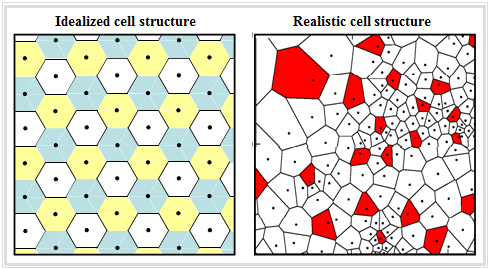
One characteristic of GSM is the »cellular network structure«, which is often idealized for simple calculations by hexagons according to the graphic on the left. This means that a coverage area with one base station per cell can be supplied without gaps if the range of the base station is at least as large as the cell radius.
This cellular structure results in the following consequences for the GSM system:
- The cell radius must be chosen smaller, the larger the carrier frequency $f_{\rm T}$ is. For the D–network $(f_{\rm T} ≈ 900 \ \rm MHz)$ the maximum cell radius is about $r=35 \ \rm km$.
- For the E–network it is significantly smaller $(r=8 \ \rm km)$ due to the higher frequency $(f_{\rm T} ≈ 1800 \ \ \rm MHz)$.
- If a mobile subscriber moves in this area, it will traverse different cells and thus be in contact with different base stations. A problem not to be neglected is the so-called "handover" when crossing a cell boundary during a call.
- If the same carrier frequency is used in all cells, "intercell interference" can occur in case of overreach. Therefore, different frequencies are often used in neighboring cells.
- In the example above, three different frequencies are used, indicated by the colors "white", "yellow" and "blue". This example is based on the re-use factor $3$.
The right graph shows a more realistic cell layout with different sized cells – depending on the subscriber density and the terrain topology.
- In addition, it can be seen that the base station does not always have to be located in the center of the cell.
- The colors "white" and "red" have no special meaning here.
GSM system architecture and network components
GSM is a hierarchically structured system of various network components. It has two main components,
- the »mobile stations« $(\rm MS$, mobile subscribers$)$
- the »fixed GSM network«.
Each mobile station consists essentially of two entities,
- the »mobile equipment« $\rm (ME)$; each ME is assigned a unique number called the "International Mobile Equipment Identity" $\rm (IMEI)$.
- the »subscriber identity module« $\rm (SIM)$ – a small PIN-protected processor and memory responsible for user data allocation and authentication.
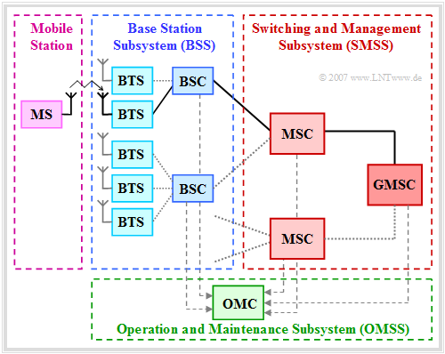
The diagram shows the structure for a so-called "Public Land Mobile Network" $\rm (PLMN)$ of GSM, i.e. the GSM system architecture. This is designed for voice transmission, but is also suitable for data transmission to a limited extent.
From this graphic, one can see:
- The mobile station communicates via radio with the nearest »base transceiver station« $\rm (BTS)$.
- Multiple BTSs are grouped together by area and are subordinated as a unit to a »base station controller« $\rm (BSC)$.
- The »base station subsystem« $\rm (BSS)$ consists of a large number of BTSs and several BSCs. In the diagram, such a BSS is outlined in blue–dashed.
- Each BSC is finally connected to a »mobile switching center« $\rm (MSC)$, whose function is comparable to a switching node in the fixed network.
The fixed GSM infrastructure can be subdivided into three subnetworks:
- the »base station subsystem« $\rm (BSS)$ ⇒ see next section for details,
- the »switching and management subsystem« $\rm (SMSS)$ ⇒ see next section but one,
- the »operation and maintenance subsystem« $\rm (OMSS)$.
The OMSS provides subscriber setup, credential verification, device blocking, charging, network component maintenance, and traffic flow control. It includes the following components:
The »operation and maintenance center« $\rm (OMC)$ monitors a portion of the overall cellular network and triggers the network's control functions. Other important functions/tasks of the OMC are the management of commercial operations, network configuration, security management and all maintenance activities regarding hardware and software. The OMC is divided into the components
- $\text{OMC-B}$ ⇒ monitoring of the base station controllers $\rm (BSC)$, and
- $\text{OMC-S}$ ⇒ control of the mobile switching centers $\rm (MSC)$.
Network control may also be centralized in a »Network Management Center« $\rm (NMC)$ that is superior to the OMCs.
Base Station Subsystem (BSS)
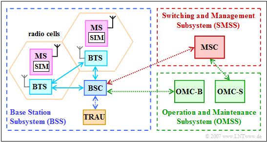
The following graphic shows in the left part a "base station subsystem", $\rm (BSS)$. Such a radio network consists of the following network components:
- The "base transceiver station" $\rm (BTS)$ provides at least one radio channel each for the useful traffic or the signaling. In addition to the RF part $($transmitting and receiving equipment$)$, it also has some components for signal and protocol processing. One or more antennas are connected to the BTS, which usually supply a 120° sector.
- To keep the base station units small, the essential control and protocol intelligence is often shifted to the "base station controller" $\rm(BSC)$. It is quite possible for multiple BTSs to be controlled by a common BSC.
- Before the signal is transferred to the switching system, the "transcoding & rate adaption unit" $\rm (TRAU)$ converts the rate of the GSM speech signal from $\text{13 kbit/s}$ to $\text{64 kbit/s}$. Furthermore, the TRAU also handles the rate adjustment for the data services.
Each BTS is assigned various parameters, namely:
- One or more radio cells are combined into one "Location Area" $\rm (LA)$. Each LA is assigned its own identification number - the so-called "Location Area Identifier" $\rm (LAI)$.
- This is broadcast regularly by the base station on the "broadcast control channel" $\rm (BCCH)$. This also allows each mobile station to determine its current location via the LAI. When the location area changes, the mobile station requests a "location update".
Other parameters of the base station subsystem include:
- The "cell allocation" $\rm (CA)$: Assignment of a set of frequencies to a BTS,
- the "cell identifier" $\rm (CI)$: Labeling of the individual cells within a LA,
- the "base transceiver station identity code" $\rm (BSIC)$: Identifier of the base transceiver station.
Switching and Management Subsystem (SMSS)
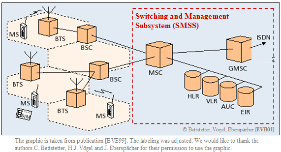
The "switching and management subsystem" $\rm (SMSS)$ consists of the mobile switching centers $\rm (MSC$ or $\rm GMSC)$ and various databases $($VLR, HLR, AUC, EIR, etc. $)$, as shown in the following graph from [BVE99][1].
Regarding this illustration, it should be noted:
- The »Mobile Switching Center« $\rm (MSC)$ – i.e., the mobile switching center – performs the same switching functions as a fixed network switching node, e.g., path search and signal path switching.
- However, in addition, an MSC must also accommodate subscriber mobility $($residence registration, handover when changing cells, and some more$)$.
- The »Gateway Mobile Switching Center« $\rm (GMSC)$ is responsible for the connection between the fixed network – for example the ISDN – and the mobile network.
- If, for example, a mobile subscriber is called from the fixed network, the GMSC determines the responsible MSC in the HLR $($see below$)$ and transfers the call.
MSC and GMSC have access to several databases:
- The »Home Location Register« $\rm (HLR)$ is a central register for subscriber data in a PLMN. It contains permanent data, but also temporary data needed for routing calls of own mobile subscribers.
- The »Visitor Location Register« $\rm (VLR)$ stores the data of all mobile stations that are currently in the administrative area of the associated MSC, i.e. also the subscribers of other network operators.
- The »Authentication Center« $\rm (AUC)$ is responsible for storing confidential data and keys.
- The »Equipment Identity Register« $\rm (EIR)$ stores serial numbers $($"International Mobile Station Equipment Identity", $\rm IMEI)$ of the terminals.
There is constant data reconciliation between the databases $($VLR, HLR, AUC, etc.$)$ of two mobile switching centers involved in a voice connection. This requires various identifiers for all subscribers, for example:
- The "mobile station roaming number" $\rm (MSRN)$ is a temporary, residence-dependent ISDN number. It is assigned to each mobile station by the locally responsible VLR and forwarded by the HLR to the GMSC upon request. This is used to route calls to a mobile station.
- The "temporary mobile subscriber identity" $\rm (TMSI)$ is another identification number that is only valid in the territory of the VLR and is used instead of the "international mobile subscriber identity" $\rm (IMSI)$ to address a mobile station.
$\text{Example 1:}$ We consider the mobile network of an operator $\rm A$ whose customer is the subscriber 1.
- The "visited location register" of operator $\rm A$ – abbreviated $\rm VLR(A)$ – contains information about the exact location $($In which cell? Which BTS?$)$ of all subscribers.
- For this subscriber 1 the entry in the "home location register" $\rm HLR(A)$ matches $\rm VLR(A)$. Thus, operator $\rm A$ recognizes that subscriber 1 is its customer and a connection is established.
Subscriber 2 is a "roaming customer" of another operator $\rm B$, who is currently in the network $\rm A$.
- The "visitor location register" of operator $\rm A$ – abbreviated $\rm VLR(A)$ – contains information about the exact whereabouts of the foreign subscriber 2 and a copy of $\rm HLR(B)$ of operator $\rm B$.
- The operator $\rm A$ thus recognizes this foreign customer and gives him clearance for roaming in his network $\rm A$. The prerequisite, however, is that a roaming contract exists between the network operators.
.
Services provided by GSM
GSM services are divided into the three categories:
- »Bearer services«,
- »teleservices«,
- »supplementary services«.
⇒ Bearer and teleservices are grouped under the generic term "telecommunication services".
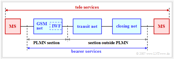
Therefore, each "public land mobile network" $\rm (PLMN)$ must provide the corresponding fixed network infrastructure and a network "interworking function" $\rm (IWF)$.
⇒ The "bearer services" are fundamental for data transmission. They provide the necessary technical facilities for the secure transport of user data. The pure transport services include:
- synchronous circuit-switched data transmission $($with 2400, 4800 or 9600 bit/s$)$,
- asynchronous circuit-switched data transmission $($with 300 or 1200 bit/s$)$,
- synchronous paket-switched data transmission $($with 2400, 4800 or 9600 bit/s$)$,
- asynchronous paket-switched data transmission $($with 300 or 9600 bit/s$)$.
⇒ The "bearer services" are further divided into two different modes:
- In the so-called "transparent mode" there is a connection between the mobile station and the MSC secured by forward error correction. This mode is characterized by a constant bit rate, a constant transmission delay and – depending on the respective channel state – a fluctuating bit error rate.
- In contrast, the "non-transparent mode" is based on the "radio link protocol" $\rm (RLP)$. By an additional ARQ procedure $($"Automatic Repeat Request$)$ blocks with too many bit errors are requested for retransmission, so that the net bit rate and the delay strongly depend on the transmission conditions.
GSM teleservices
The second category of GSM services are »teleservices«. These are end-to-end services that usually do not require network transition conversion $($"interworking function", $\rm IWF)$. In the above graph, $\rm MS$ denotes the terminal equipment of the mobile station.
The main teleservices are:
- the »telephone service«:
This basic service for the transmission of digitally-encoded speech signals uses a bidirectional as well as symmetrical point-to-point connection and offers services such as call forwarding, call blocking and closed user groups; - the »fax service«, which uses a transparent carrier service to transmit data;
- the »short message service« provided by GSM since 1996:
This allows point-to-point messages with a maximum length of 160 alphanumeric characters to be transmitted to or from a mobile station using a connectionless packet-switched protocol.
The »supplementary services« as the third category of GSM services modify and complement the functionality of a GSM telecommunications service. Phase 1 GSM offers the same supplementary services as $\text{ISDN}$, for example,
- "call display",
- "call forwarding", and
- "call restriction".
More recent phase 2+ GSM services are:
- $\text{High Speed Circuit-Switched Data}$ $\rm (HSCSD$, circuit-switched$)$
- $\text{General Packet Radio Service}$ $\rm (GPRS$, packet-switched$)$, and
- $\text{Enhanced Data Rates for GSM Evolution}$ $\rm (EDGE$, higher-rate data transmission$)$.
Exercises for the chapter
Exercise 3.1: GSM Network Components
References
- ↑ Bettstetter, C.; Vögel, H.J.; Eberspächer, J.: GSM Phase 2+ General Packet Radio Service GPRS: Architecture, Protocols, and Air Interface. In: IEEE Communications Surveys & Tutorials, Vol. 2 (1999) No. 3, pp. 2-14.
