Difference between revisions of "Mobile Communications/Characteristics of UMTS"
| Line 8: | Line 8: | ||
== Requirements for third generation mobile radio systems == | == Requirements for third generation mobile radio systems == | ||
<br> | <br> | ||
| − | The main motivation for the development of '''Third generation mobile radio systems'' was the realization that 2G–systems could not satisfy the bandwidth requirements for the use of multimedia services. | + | The main motivation for the development of '''Third generation mobile radio systems''' was the realization that 2G–systems could not satisfy the bandwidth requirements for the use of multimedia services. |
[[File:EN_Mob_T_3_4_S1.png|right|frame|Development of the mobile radio systems|class=fit]] | [[File:EN_Mob_T_3_4_S1.png|right|frame|Development of the mobile radio systems|class=fit]] | ||
| Line 38: | Line 38: | ||
*in the ''medical field:'' telemedicine.<br><br> | *in the ''medical field:'' telemedicine.<br><br> | ||
| − | |||
| − | |||
| Line 60: | Line 58: | ||
*<b>UTRA–TDD</b> ⇒ ''UMTS Terrestrial Radio Access – Time Division Duplex'': <br>Here, five bands of $\text{5 MHz}$ bandwidth are provided in which both uplink and downlink data are to be transmitted by means of time division multiplexing. For UTRA–TDD the frequencies between $\text{1900}$ and $\text{1920 MHz}$ (four channels) and between $\text{202020}$ and $\text{2025 MHz}$ (one channel) are reserved.<br> | *<b>UTRA–TDD</b> ⇒ ''UMTS Terrestrial Radio Access – Time Division Duplex'': <br>Here, five bands of $\text{5 MHz}$ bandwidth are provided in which both uplink and downlink data are to be transmitted by means of time division multiplexing. For UTRA–TDD the frequencies between $\text{1900}$ and $\text{1920 MHz}$ (four channels) and between $\text{202020}$ and $\text{2025 MHz}$ (one channel) are reserved.<br> | ||
| − | |||
| − | |||
| Line 82: | Line 78: | ||
[[File:P ID2209 Mob T 3 4 S3 v1.png|right|frame|UMTS-access level (with line switching)|class=fit]] | [[File:P ID2209 Mob T 3 4 S3 v1.png|right|frame|UMTS-access level (with line switching)|class=fit]] | ||
| − | <The diagram shows the UMTS–architecture for circuit switching | + | <br>The diagram shows the UMTS–architecture for circuit switching, where the <i>Core Network</i> (CN) is organized similarly to the GSM–architecture. |
| − | The [[Examples_of_Communication_Systems/UMTS%E2%80%93Netzarchitektur#Architektur_der_Zugangsebene|''' checkLink:_Buch_9 ⇒ ''' System Architecture for Packet Switching]] | + | The [[Examples_of_Communication_Systems/UMTS%E2%80%93Netzarchitektur#Architektur_der_Zugangsebene|''' checkLink:_Buch_9 ⇒ ''' System Architecture for Packet Switching]] differs fundamentally in the following points: |
*Here, the communication partners do not use the channel assigned to them exclusively, but the packets are mixed with those of other users. | *Here, the communication partners do not use the channel assigned to them exclusively, but the packets are mixed with those of other users. | ||
| Line 96: | Line 92: | ||
[[File:EN Mob T 3 4 S4.png|center|frame|Principle and signal characteristics with "DS-CDMA" for two users|class=fit]] | [[File:EN Mob T 3 4 S4.png|center|frame|Principle and signal characteristics with "DS-CDMA" for two users|class=fit]] | ||
The diagram shows the principle using a simplified model and exemplary signals for the "user 1". For simplification the noise signal $n(t) \equiv 0$ is set for the displayed signals. It is valid: | The diagram shows the principle using a simplified model and exemplary signals for the "user 1". For simplification the noise signal $n(t) \equiv 0$ is set for the displayed signals. It is valid: | ||
| − | *The two source signals $q_1(t)$ and $q_2(t)$ use the same AWGN–channel without interfering with each other. The bit duration of each data signal is $T_{\rm B}$.<br> | + | *The two source signals $q_1(t)$ and $q_2(t)$ use the same AWGN–channel without interfering with each other. The bit duration of each data signal is $T_{\rm B}$.<br> |
*Each of the data signals is multiplied by an assigned spreading code, $c_1(t)$ or $c_2(t)$ . The sum signal is transmitted; | *Each of the data signals is multiplied by an assigned spreading code, $c_1(t)$ or $c_2(t)$ . The sum signal is transmitted; | ||
| Line 125: | Line 121: | ||
*No predecessor or successor of a code may be used. | *No predecessor or successor of a code may be used. | ||
*In the example eight spreading codes with the spreading factor $J = 8$ could be used. | *In the example eight spreading codes with the spreading factor $J = 8$ could be used. | ||
| − | *Or the four codes highlighted in yellow | + | *Or the four codes highlighted in yellow $J = 2$ once, $J = 4$ once and the $J = 8$ twice. |
*The lower four codes with the spreading factor $J = 8$ cannot be used here, since they all start with "$+1 \ -1$ " which is already occupied by the OVSF–codes with spreading factor $J = 2$ .}} | *The lower four codes with the spreading factor $J = 8$ cannot be used here, since they all start with "$+1 \ -1$ " which is already occupied by the OVSF–codes with spreading factor $J = 2$ .}} | ||
| Line 132: | Line 128: | ||
| − | == | + | == Additional scrambling in UMTS == |
<br> | <br> | ||
| − | [[File:EN_Mob_T_3_4_S5.png|right|frame| | + | [[File:EN_Mob_T_3_4_S5. png|right|frame|Scrambling in UMTS|class=fit]] |
| − | + | In order to get more spreading codes and to be able to serve more participants, after the band spreading using $c(t)$ the sequence is again scrambled chip by chip using $w(t)$ without further spreading. | |
| − | + | The use of quasi–orthogonal codes makes sense, because the amount of orthogonal codes is limited and different participants can use the same spreading codes due to the scrambling. | |
<br clear=all> | <br clear=all> | ||
{{BlaueBox|TEXT= | {{BlaueBox|TEXT= | ||
| − | $\text{ | + | $\text{Conclusion:}$ |
| − | * | + | *The scrambling code $w(t)$ has the same length and rate as $c(t)$.<br> |
| − | * | + | *Due to the scrambling, the codes lose their complete orthogonality; they are called <i>quasi–othogonal</i>. |
| − | * | + | * In these codes, the [[Theory_of_Stochastic_Signals/Kreuzkorrelationsfunktion_und_Kreuzleistungsdichte#Definition_der_Kreuzkorrelationsfunktion |''' checkLink:_Buch_3 ⇒ ''' Cross-Correlation Function]] (CCF) between different spreading codes is not equal to zero. |
| − | * | + | *But they are characterized by a distinct [[Theory_of_Stochastic_Signals/Autokorrelationsfunktion_(AKF)#Zufallsprozesse_.281.29| ''' checkLink:_Buch_3 ⇒ ''' ACF–Value]] around zero, which facilitates detection at the receiver.}} |
| − | [[File:P ID1537 Bei T 4 3 S3b v2.png|right|frame| | + | [[File:P ID1537 Bei T 4 3 S3b v2.png|right|frame|Example generator for gold codes with $N = 18$|class=fit]] |
{{GraueBox|TEXT= | {{GraueBox|TEXT= | ||
| − | $\text{ | + | $\text{Example 2:}$ In UMTS, so-called [https://en.wikipedia.org/wiki/Gold_code Gold codes] are used for scrambling: |
| − | * | + | *The graphic from [3gpp]<ref name='3gpp'>3gpp Group: ''UMTS Release 6 - Technical Specification 25.213 V6.4.0.'', Sept. 2005.</ref> shows the block diagram for the generation of such codes. |
| − | * | + | *At first two different [[Theory_of_Stochastic_Signals/Erzeugung_von_diskreten_Zufallsgr%C3%B6%C3%9Fen#Pseudozufallsgr.C3.B6.C3.9Fen|Pseudonoise– sequences]] of the same length $($here: $N = 18)$ aregenerated in parallel by means of shift registers and then added bitwise with <i>XOR–gates</i> .}} |
<br clear =all> | <br clear =all> | ||
| − | [[File:EN_Mob_T_3_4_S5b.png|left|frame| | + | [[File:EN_Mob_T_3_4_S5b.png|left|frame|Some examples and properties of suitable spreading and scrambling codes|class=fit]] |
<br><br><br> | <br><br><br> | ||
| − | * | + | *In the uplink, each mobile station has its own scrambling code and the separation of the individual channels is done using the same code. |
| − | * | + | *In the downlink, on the other hand, each service area of a "Node B" has a common scrambling code.<br> |
| − | * | + | *The table on the right summarizes some data of the spreading and scrambling codes.<br> |
<br clear =all> | <br clear =all> | ||
| − | == Modulation | + | == Modulation and pulse shaping for UMTS == |
<br> | <br> | ||
| − | + | In UMTS the following modulation methods are used in FDD–mode: | |
| − | * | + | *In the downlink [[Modulation_Methods/Quadratur%E2%80%93Amplitudenmodulation#Weitere_Signalraumkonstellationen| ''' checkLink:_Buch_5 ⇒ ''' Quaternary Phase Shift Keying]] (QPSK) is used. User data (DPDCH–channel) and control data (DPCCH–channel) are multiplexed in time.<br> |
| + | |||
| + | *A [https://en.wikipedia.org/wiki/Phase-shift_keying Dual–Channel–BPSK] is used in the uplink. This has the same signal space as QPSK, but the $I$ and $Q$ components transmit the information of different channels.<br><br> | ||
| − | + | [[File:EN_Mob_T_3_4_S6.png|right|frame|Modulation and pulse shaping for UMTS|class=fit]] | |
| + | The diagram shows the $I/Q$–Multiplexing method</i>, another name for the Dual–Channel–BPSK, in the equivalent low-pass range. <br> | ||
| − | + | *The spread user data of the DPDCH–channel is modulated and transmitted on the inphase component $I$ (real part) and the control data of the DPCCH–channel, also spread, is modulated on the quadrature component $Q$ (imaginary part).<br> | |
| − | |||
| − | * | + | *The quadrature component is weighted with the square root of the power ratio $G$ between $I$ and $Q$ to compensate for power differences. Then the sum signal $(I + {\rm j} \cdot Q)$ is multiplied by a complex scrambling code.<br> |
| − | * | + | *Finally the pulse shaping is done with $g_s(t)$ corresponding to the [[Digital_Signal_Transmission/Optimierung_der_Basisband%C3%BCbertragungssysteme#Wurzel.E2.80.93Nyquist.E2.80.93Systeme|''' checkLink:_Buch_6 ⇒ ''' Root Raised Cosine]]. Since the receive filter is adapted to $G_s(f)$ the overall frequency response thus fulfills the [[Digital_Signal_Transmission/Eigenschaften_von_Nyquistsystemen#Erstes_Nyquistkriterium_im_Frequenzbereich|''' checkLink:_Buch_6 ⇒ ''' first Nyquist criterion]].<br><br> |
| − | + | Further information on this topic can be found in the section [[Examples_of_Communication_Systems/Nachrichtentechnische_Aspekte_von_UMTS#Pulsformung_und_Modulation_in_UMTS|''' checkLink:_Buch_9 ⇒ ''' | |
| + | Pulse_forming and modulation in UMTS]] of the book "Examples of communication systems". There you will also find a graphic with the Nyquist frequency response $H(f)$. It is a [[Linear_and_Time_Invariant_Systems/Einige_systemtheoretische_Tiefpassfunktionen#Cosinus-Rolloff-Tiefpass|''' checkLink:_Buch_2 ⇒ ''' Raised Cosine]] with the following dimensioning: | ||
| + | *The UMTS–chip rate is $R_{\rm C} = 3.84 \ \rm Mbit/s$. The center of the slope must be at $f_{\rm N} =R_{\rm C}/2 = 1.92 \ \rm MHz$ to avoid pulse interference. For $f_{\rm N}$ is then | ||
| + | $$H(f = \pm f_{\rm N}) = 0.5.$$ | ||
| − | + | *For UMTS the rolloff–factor $r = 0.22$ has been defined. | |
| − | * | + | *This results in the two cutoff frequencies for $f_1 = 0.78 \cdot f_{\rm N} \approx 1.498 \ \rm MHz$ and $f_2 = 1.22 \cdot f_{\rm N} \approx 2.342 \ \rm MHz$.<br> |
| − | |||
| − | * | + | *The required absolute frequency bandwidth is thus $B = 2 \cdot f_2 = 1.22 \cdot f_{\rm N} \approx 4.684 \ \rm MHz$, so that for each UMTS–channel with $5 \ \rm MHz$ sufficient bandwidth is available.<br><br> |
| − | |||
| − | |||
| − | == | + | |
| + | |||
| + | == UMTS extensions HSDPA and HSUPA == | ||
<br> | <br> | ||
| − | + | In order to meet the ever-increasing demand for higher data rates in mobile communications, the UMTS–standard has been continuously developed. The most important changes within the third generation resulted from the introduction of | |
| − | *[[Examples_of_Communication_Systems/Weiterentwicklungen_von_UMTS#High.E2.80.93Speed_Downlink_Packet_Access| '''HSDPA''']]: <i>High Speed Downlink Packet Access</i> (Release 5, 2002, | + | *[[Examples_of_Communication_Systems/Weiterentwicklungen_von_UMTS#High.E2.80.93Speed_Downlink_Packet_Access| ''' checkLink:_Buch_9 ⇒ ''' '''HSDPA''']]: <i>High Speed Downlink Packet Access</i> (Release 5, 2002, market launch 2006) and <br> |
| + | |||
| + | *[[Examples_of_Communication_Systems/Weiterentwicklungen_von_UMTS#High.E2.80.93Speed_Uplink_Packet_Access| ''' checkLink:_Buch_9 ⇒ ''' '''HSUPA''']]: <i>High Speed Uplink Packet Access</i> (Release 6, 2005, market launch 2007).<br><br> | ||
| + | |||
| + | Together, HSDPA and HSDUPA result in the '''HSPA–Standard'''.<br> | ||
| − | * | + | The main motivation for these further developments was to increase data rate/throughput and minimize response times in packet-switched transmission. |
| + | *For the downlink, data rates up to $\text{7 Mbit/s}$ were quite feasible with HSDPA since 2011. | ||
| + | *But also (more theoretical) <i>best–Case</i>–rates of up to $\text{28.8 Mbit/s}$ (with 64–QAM and MIMO) were given. | ||
| − | |||
| − | + | These increases were achieved by | |
| − | * | + | *the introduction of additional [[Examples_of_Communication_Systems/Weiterentwicklungen_von_UMTS#Zus.C3.A4tzliche_Kan.C3.A4le_in_HSDPA | ''' checkLink:_Buch_9 ⇒ ''' shared channels]] (for example '''HS–DSCH'''),<br> |
| − | |||
| + | *the [[Examples_of_Communication_Systems/Weiterentwicklungen_von_UMTS#HARQ.E2.80.93Verfahren_und_Node_B_Scheduling| ''' checkLink:_Buch_9 ⇒ ''' Hybrid–ARQ Procedure]] ('''HARQ''') and [[Examples_of_Communication_Systems/Weiterentwicklungen_von_UMTS#HARQ.E2.80.93Verfahren_und_Node_B_Scheduling| ''' checkLink:_Buch_9 ⇒ ''' Node B–Scheduling]],<br>. | ||
| − | + | *the use of [[Examples_of_Communication_Systems/Weiterentwicklungen_von_UMTS#Adaptive_Modulation.2C_Codierung_und_.C3.9Cbertragungsrate| adaptive $M$–QAM, coding and transmission rate]].<br><br> | |
| − | * | ||
| − | + | In addition to the use of HARQ and Node–B–Scheduling, the significant improvement through HSUPA is due to the introduction of the additional upstream channel '''E–DCH''' (<i>Enhanced Dedicated Channel</i>). | |
| + | *Among other things, this minimizes the influence of applications with very different and sometimes very intensive data volumes ( <i>Bursty Traffic</i> ). However, unlike UMTS–R99, HSUPA does not guarantee a fixed bandwidth in the upward direction.<br> | ||
| − | * | + | *This flexible and efficient bandwidth allocation depending on channel conditions increased the cell capacity enormously. In practice, transmission rates of up to $\text{3 Mbit/s}$ were achieved from 2011, even when taking into account the large number of users. The values specified by developers for best conditions were significantly higher.<br> |
| − | + | ==Exercises for chapter== | |
| − | |||
| − | |||
| − | |||
<br> | <br> | ||
[[Aufgaben:Exercise 3.6: FDMA, TDMA and CDMA]] | [[Aufgaben:Exercise 3.6: FDMA, TDMA and CDMA]] | ||
| − | [[Aufgaben: | + | [[Aufgaben:Exercise 3.6Z: Concepts of 3G Mobile Communications Systems]] |
| − | [[Aufgaben: | + | [[Aufgaben:Exercise 3.7: PN Modulation]] |
| − | [[Aufgaben: | + | [[Aufgaben:Exercise 3.7Z: Spread Spectrum in UMTS]] |
| − | [[Aufgaben: | + | [[Aufgaben:Exercise 3.8: OVSF Codes]] |
| − | [[Aufgaben: | + | [[Aufgaben:Exercise 3.9: Further Developments of UMTS]] |
| − | == | + | ==List of sources== |
{{Display}} | {{Display}} | ||
Revision as of 19:17, 30 August 2020
Contents
- 1 Requirements for third generation mobile radio systems
- 2 The IMT-2000 standard
- 3 System architecture and basic units for UMTS
- 4 CDMA - Multiple access with UMTS
- 5 Requirements for the spreading codes
- 6 Additional scrambling in UMTS
- 7 Modulation and pulse shaping for UMTS
- 8 UMTS extensions HSDPA and HSUPA
- 9 Exercises for chapter
- 10 List of sources
Requirements for third generation mobile radio systems
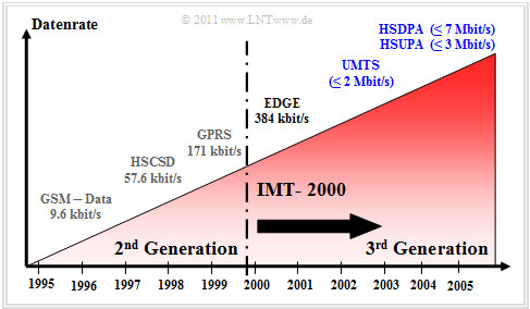
The main motivation for the development of Third generation mobile radio systems was the realization that 2G–systems could not satisfy the bandwidth requirements for the use of multimedia services.
The graph shows the development of mobile radio systems from 1995 to 2006 in terms of performance. The specified data rates were still realistic for 2011 with no more than two active users in one cell. The maximum values often stated by providers were mostly not reached in practice.
Third-generation mobile communications systems should have a greater bandwidth and sufficient reserve capacity to ensure a high quality of service (QoS) even with growing requirements.
Prior to the development of the 3G–systems, the International Telecommunication Union (ITU) created a catalog of requirements which includes the following general conditions:
- High data rates from $\text{144 kbit/s}$ (Standard) to $\text{2 Mbit/s}$ (In-door),
- symmetric and asymmetric data transmission (IP–services),
- high speech quality and high spectral efficiency,
- global accessibility and distribution,
- seamless transition from and to second generation systems,
- Applicability independent of the network used (Virtual Home Environment ),
- Provision of circuit-switched and packet-switched transmission.
During the introduction of UMTS (Universal Mobile Telecommunication System) as the best known 3G–standard, the expansion and diversification of the services offered was a decisive motive. A UMTS–capable terminal device must support a number of complex and multimedia applications in addition to the classic services (voice transmission, messaging, etc.), including >br>
- with regard to Information: Internet surfing (Info–on–demand), online print media,
- regarding Communication: video and audio conference, fax, ISDN, messaging,
- regarding Entertainment: Mobile TV, Video–on–Demand, Online–Gaming,
- in the business area: Interactive shopping, E–Commerce,
- in the technical area: Online–support, distribution service (language and data),
- in the medical field: telemedicine.
The IMT-2000 standard
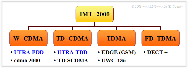
Around 1990, the International Telecommuncation Union (ITU) created the Standard IMT-2000 (International Mobile Telecommunications at the year 2000), which was to make the above-mentioned requirements possible. IMT–2000 comprises a number of third-generation mobile communications systems that have been brought closer together in the course of standardization to enable the development of common terminals for all these standards.
In order to take into account different preliminary work and to give network operators the possibility to continue to use existing network architectures in part, IMT–2000 contains several individual standards. These can be roughly divided into four categories:
- W–CDMA: This includes the FDD component of the European UMTS–standard and the American cdma2000–system.
- CDMA: This group includes the TDD–component of UMTS as well as the Chinese TD–SCDMA.
integrated in it.
- TDMA: A further development of the GSM–derived EDGE and its American counterpart UWC–136, also known as D–AMPS.
- FD–TDMA:nbsp; further development of the European cordless–telephony–DECT standard (Digital Enhanced Cordless Telecommunication).
We concentrate here on the mobile communications system UMTS developed in Europe, which supports the two standards W–CDMA and TD–CDMA of the system family IMT–2000, under the following designations:
- UTRA–FDD ⇒ UMTS Terrestrial Radio Access – Frequency Division Duplex:
This consists of twelve paired uplink and downlink frequency bands each $\text{5 MHz}$ bandwidth. In Europe these are between $\text{1920}$ and $\text{1980 MHz}$ in the uplink and between $\text{2110}$ and $\text{2170 MHz}$ in the downlink. In the summer of 2000, the auction of the licenses for Germany with a 20-year term brought in approx. 50 billion Euro.
- UTRA–TDD ⇒ UMTS Terrestrial Radio Access – Time Division Duplex:
Here, five bands of $\text{5 MHz}$ bandwidth are provided in which both uplink and downlink data are to be transmitted by means of time division multiplexing. For UTRA–TDD the frequencies between $\text{1900}$ and $\text{1920 MHz}$ (four channels) and between $\text{202020}$ and $\text{2025 MHz}$ (one channel) are reserved.
System architecture and basic units for UMTS
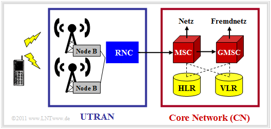
The network–architecture of UMTS can be divided into two main blocks.
The UMTS Terrestrial Radio Access Network (UTRAN) ensures the wireless transmission of data between the transport level and the radio network level. This includes the base stations and the control nodes, whose functions are described below:
- A UMTS–base station is, also called Node B , comprises the antenna system and the CDMA–receiver and is directly connected to the radio interfaces of all users in the cell. The tasks of a "Node B" include data rate matching, data and channel (de)coding, interleaving, and modulation or demodulation. Each base station can serve one or more cells (sectors).
- The Radio Network Controller (RNC) is responsible for controlling the base stations. It is also responsible within the cells for call acceptance control, encryption and decryption, conversion to ATM (Asynchronous Tranfer Mode), channel assignment, handover and power control.
The Core Network (CN) takes over the switching of the data within the UMTS–network. For this purpose, it contains the following hardware and software components at circuit switching :
- The Mobile Switching Center (MSC) is responsible for localization/authentication, routing of calls, handover and encryption of user data.
- The Gateway Mobile Switching Center (GMSC) organizes the connection to other networks, for example to the landline network.
- MSC and GMSC have access to various databases like checkLink:_Buch_9 ⇒
Home Location Register (HLR) and checkLink:_Buch_9 ⇒ Visitor Location Register (VLR).
The diagram shows the UMTS–architecture for circuit switching, where the Core Network (CN) is organized similarly to the GSM–architecture.
The checkLink:_Buch_9 ⇒ System Architecture for Packet Switching differs fundamentally in the following points:
- Here, the communication partners do not use the channel assigned to them exclusively, but the packets are mixed with those of other users.
- One finds there similar components as with the GSM–Extension checkLink:_Buch_9 ⇒ General Packet Radio Service (GPRS).
CDMA - Multiple access with UMTS
UMTS uses the multiple access method checkLink:_Buch_5 ⇒ Direct Sequence Code Division Multiple Access (DS–CDMA). The procedure is sometimes also called "PN–Modulation".
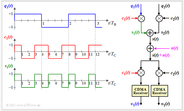
The diagram shows the principle using a simplified model and exemplary signals for the "user 1". For simplification the noise signal $n(t) \equiv 0$ is set for the displayed signals. It is valid:
- The two source signals $q_1(t)$ and $q_2(t)$ use the same AWGN–channel without interfering with each other. The bit duration of each data signal is $T_{\rm B}$.
- Each of the data signals is multiplied by an assigned spreading code, $c_1(t)$ or $c_2(t)$ . The sum signal is transmitted;
- $$s(t) = s_1(t) + s_2(t) = q_1(t) \cdot c_1(t) + q_2(t) \cdot c_2(t).$$
- The bandwidths of the partial signals $s_1(t)$ and $s_2(t)$ as well as of the resulting transmitedt signal $s(t)$ are larger than the bandwidths of $q_1(t)$ and $q_2(t)$ by the 'spreading factor $ J = T_{\rm C}/T_{\rm B}$ . For the graphic $J = 4$ was chosen.
- The same spreading codes $c_1(t)$ or $c_2(t)$ are added multiplicatively to the receiver. In the case of orthogonal codes and small AWGN–noise $n(t)$ the data signals can then be separated again. This means that $v_1(t) = q_1(t)$ and $v_2(t) = q_2(t)$.
- If AWGN–noise is present, the digital output signals are different from the input signals, but the probability of error is not increased by the other users as long as the used spreading sequences are orthogonal.
- In the example $J =4$ one could thus transmit users over the same channel without interference, but only if there are $J =4$ orthogonal spreading codes.
Requirements for the spreading codes
The spreading codes for UMTS should
- be orthogonal to each other to avoid mutual influence of the users,
- allow a flexible realization of different spreading factors $J$.
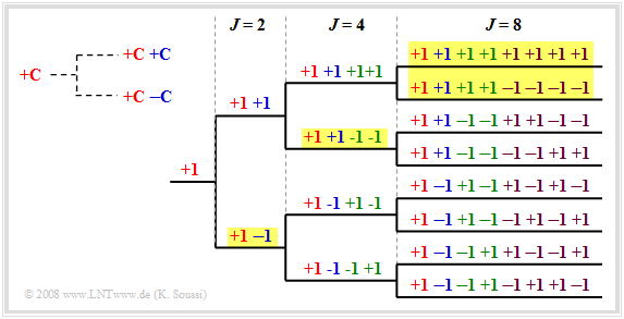
$\text{Example 1:}$ An example for spreading codes are the Orthogonal Variable Spreading Factor, OVSF), which provide codes of length between $J =4$ and $J =512$ .
These can be created with the help of a code tree, as shown in the graphic. Thereby in each branching from a code $C$ two new codes result $(+C \ +\hspace{-0.05cm}C)$ and $(+C \ -\hspace{-0.05cm}C)$.
To be noted:
- No predecessor or successor of a code may be used.
- In the example eight spreading codes with the spreading factor $J = 8$ could be used.
- Or the four codes highlighted in yellow $J = 2$ once, $J = 4$ once and the $J = 8$ twice.
- The lower four codes with the spreading factor $J = 8$ cannot be used here, since they all start with "$+1 \ -1$ " which is already occupied by the OVSF–codes with spreading factor $J = 2$ .
The situation described here is also clarified by the applet OVSF–Codes .
Additional scrambling in UMTS
In order to get more spreading codes and to be able to serve more participants, after the band spreading using $c(t)$ the sequence is again scrambled chip by chip using $w(t)$ without further spreading.
The use of quasi–orthogonal codes makes sense, because the amount of orthogonal codes is limited and different participants can use the same spreading codes due to the scrambling.
$\text{Conclusion:}$
- The scrambling code $w(t)$ has the same length and rate as $c(t)$.
- Due to the scrambling, the codes lose their complete orthogonality; they are called quasi–othogonal.
- In these codes, the checkLink:_Buch_3 ⇒ Cross-Correlation Function (CCF) between different spreading codes is not equal to zero.
- But they are characterized by a distinct checkLink:_Buch_3 ⇒ ACF–Value around zero, which facilitates detection at the receiver.
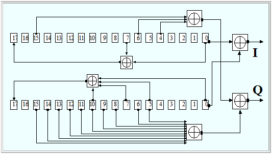
$\text{Example 2:}$ In UMTS, so-called Gold codes are used for scrambling:
- The graphic from [3gpp][1] shows the block diagram for the generation of such codes.
- At first two different Pseudonoise– sequences of the same length $($here: $N = 18)$ aregenerated in parallel by means of shift registers and then added bitwise with XOR–gates .
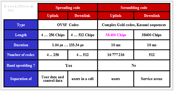
- In the uplink, each mobile station has its own scrambling code and the separation of the individual channels is done using the same code.
- In the downlink, on the other hand, each service area of a "Node B" has a common scrambling code.
- The table on the right summarizes some data of the spreading and scrambling codes.
Modulation and pulse shaping for UMTS
In UMTS the following modulation methods are used in FDD–mode:
- In the downlink checkLink:_Buch_5 ⇒ Quaternary Phase Shift Keying (QPSK) is used. User data (DPDCH–channel) and control data (DPCCH–channel) are multiplexed in time.
- A Dual–Channel–BPSK is used in the uplink. This has the same signal space as QPSK, but the $I$ and $Q$ components transmit the information of different channels.
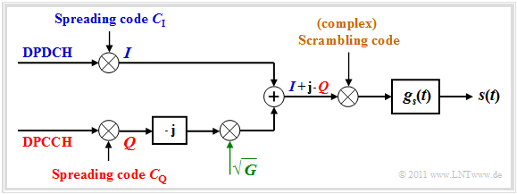
The diagram shows the $I/Q$–Multiplexing method, another name for the Dual–Channel–BPSK, in the equivalent low-pass range.
- The spread user data of the DPDCH–channel is modulated and transmitted on the inphase component $I$ (real part) and the control data of the DPCCH–channel, also spread, is modulated on the quadrature component $Q$ (imaginary part).
- The quadrature component is weighted with the square root of the power ratio $G$ between $I$ and $Q$ to compensate for power differences. Then the sum signal $(I + {\rm j} \cdot Q)$ is multiplied by a complex scrambling code.
- Finally the pulse shaping is done with $g_s(t)$ corresponding to the checkLink:_Buch_6 ⇒ Root Raised Cosine. Since the receive filter is adapted to $G_s(f)$ the overall frequency response thus fulfills the checkLink:_Buch_6 ⇒ first Nyquist criterion.
Further information on this topic can be found in the section checkLink:_Buch_9 ⇒ Pulse_forming and modulation in UMTS of the book "Examples of communication systems". There you will also find a graphic with the Nyquist frequency response $H(f)$. It is a checkLink:_Buch_2 ⇒ Raised Cosine with the following dimensioning:
- The UMTS–chip rate is $R_{\rm C} = 3.84 \ \rm Mbit/s$. The center of the slope must be at $f_{\rm N} =R_{\rm C}/2 = 1.92 \ \rm MHz$ to avoid pulse interference. For $f_{\rm N}$ is then
$$H(f = \pm f_{\rm N}) = 0.5.$$
- For UMTS the rolloff–factor $r = 0.22$ has been defined.
- This results in the two cutoff frequencies for $f_1 = 0.78 \cdot f_{\rm N} \approx 1.498 \ \rm MHz$ and $f_2 = 1.22 \cdot f_{\rm N} \approx 2.342 \ \rm MHz$.
- The required absolute frequency bandwidth is thus $B = 2 \cdot f_2 = 1.22 \cdot f_{\rm N} \approx 4.684 \ \rm MHz$, so that for each UMTS–channel with $5 \ \rm MHz$ sufficient bandwidth is available.
UMTS extensions HSDPA and HSUPA
In order to meet the ever-increasing demand for higher data rates in mobile communications, the UMTS–standard has been continuously developed. The most important changes within the third generation resulted from the introduction of
- checkLink:_Buch_9 ⇒ HSDPA: High Speed Downlink Packet Access (Release 5, 2002, market launch 2006) and
- checkLink:_Buch_9 ⇒ HSUPA: High Speed Uplink Packet Access (Release 6, 2005, market launch 2007).
Together, HSDPA and HSDUPA result in the HSPA–Standard.
The main motivation for these further developments was to increase data rate/throughput and minimize response times in packet-switched transmission.
- For the downlink, data rates up to $\text{7 Mbit/s}$ were quite feasible with HSDPA since 2011.
- But also (more theoretical) best–Case–rates of up to $\text{28.8 Mbit/s}$ (with 64–QAM and MIMO) were given.
These increases were achieved by
- the introduction of additional checkLink:_Buch_9 ⇒ shared channels (for example HS–DSCH),
- the use of adaptive $M$–QAM, coding and transmission rate.
In addition to the use of HARQ and Node–B–Scheduling, the significant improvement through HSUPA is due to the introduction of the additional upstream channel E–DCH (Enhanced Dedicated Channel).
- Among other things, this minimizes the influence of applications with very different and sometimes very intensive data volumes ( Bursty Traffic ). However, unlike UMTS–R99, HSUPA does not guarantee a fixed bandwidth in the upward direction.
- This flexible and efficient bandwidth allocation depending on channel conditions increased the cell capacity enormously. In practice, transmission rates of up to $\text{3 Mbit/s}$ were achieved from 2011, even when taking into account the large number of users. The values specified by developers for best conditions were significantly higher.
Exercises for chapter
Exercise 3.6: FDMA, TDMA and CDMA
Exercise 3.6Z: Concepts of 3G Mobile Communications Systems
Exercise 3.7Z: Spread Spectrum in UMTS
Exercise 3.9: Further Developments of UMTS
List of sources
- ↑ 3gpp Group: UMTS Release 6 - Technical Specification 25.213 V6.4.0., Sept. 2005.
