Difference between revisions of "Aufgaben:Exercise 3.7Z: Spread Spectrum in UMTS"
m (Text replacement - "Mobile Kommunikation/Die Charakteristika von UMTS" to "Mobile_Communications/Characteristics_of_UMTS") |
|||
| Line 4: | Line 4: | ||
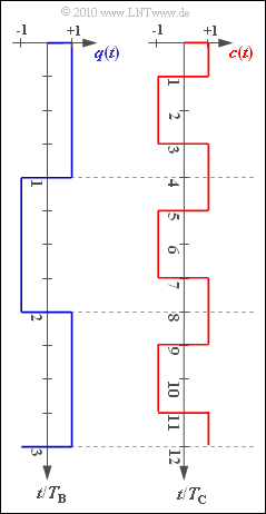
[[File:P_ID2260__Bei_Z_4_5.png|right|frame|Source signal and spread signal]] | [[File:P_ID2260__Bei_Z_4_5.png|right|frame|Source signal and spread signal]] | ||
| − | For UMTS/CDMA, the so-called PN modulation is applied: | + | For UMTS/CDMA, the so-called "PN modulation" is applied: |
| − | *The rectangular digital signal $q(t)$ is multiplied by the spread signal $c(t)$ and gives the | + | *The rectangular digital signal $q(t)$ is multiplied by the spread signal $c(t)$ and gives the transmission signal $s(t)$. |
| − | *This is by the spreading factor $J$ higher | + | *This is by the spreading factor $J$ of higher frequency than $q(t)$; this is called "band spreading". |
| − | |||
| − | The | + | At the receiver the same spreading signal $c(t)$ is added (namely in phase!). This reverses the band spreading ⇒ "band compression". |
| + | |||
| + | The graphic shows exemplary signal characteristics of $q(t)$ und $c(t)$. | ||
| Line 18: | Line 19: | ||
''Notes:'' | ''Notes:'' | ||
| − | *This | + | *This task refers to the chapter [[Mobile_Communications/Characteristics_of_UMTS|Characteristics of UMTS]]. |
| − | *Reference is made to the chapter [[Examples_of_Communication_Systems/ | + | *Reference is made to the chapter [[Examples_of_Communication_Systems/Telecommunications_Aspects_of_UMTS|Telecommunications Aspects of UMTS]] in the book "Examples of Communication_Systems". |
| − | *For the calculation of the chip duration $T_{\rm C}$ , please refer to page [[Examples_of_Communication_Systems/ | + | *For the calculation of the chip duration $T_{\rm C}$ , please refer to page [[Examples_of_Communication_Systems/UMTS_Network_Architecture#Physical_channels|Physical channels]] . |
| − | *There you will find, among other things, the information important for this task, which is transmitted on the so-called | + | *There you will find, among other things, the information important for this task, which is transmitted on the so-called "Dedicated Physical Channel" $\rm (DPCH)$ in ten milliseconds exactly $15 \cdot 2560 \ \rm Chips$. |
| − | *In subtask '''(5)''', the system asks for | + | *In subtask '''(5)''', the system asks for "sending chips". For example, the "sending chip" $s_{3}$ denotes the constant signal value of $s(t)$ in the time interval $2T_{\rm C}$ ... $3T_{\rm C}$. |
| Line 51: | Line 52: | ||
$R_{\rm B} \ = \ $ { 960 3% } $\ \rm kbit/s $ | $R_{\rm B} \ = \ $ { 960 3% } $\ \rm kbit/s $ | ||
| − | {What | + | {What are the "chips" of the signal $s(t)$? |
|type="{}"} | |type="{}"} | ||
$s_{3} \ = \ $ { -1.03--0.97 } | $s_{3} \ = \ $ { -1.03--0.97 } | ||
Revision as of 15:01, 25 January 2021
For UMTS/CDMA, the so-called "PN modulation" is applied:
- The rectangular digital signal $q(t)$ is multiplied by the spread signal $c(t)$ and gives the transmission signal $s(t)$.
- This is by the spreading factor $J$ of higher frequency than $q(t)$; this is called "band spreading".
At the receiver the same spreading signal $c(t)$ is added (namely in phase!). This reverses the band spreading ⇒ "band compression".
The graphic shows exemplary signal characteristics of $q(t)$ und $c(t)$.
Notes:
- This task refers to the chapter Characteristics of UMTS.
- Reference is made to the chapter Telecommunications Aspects of UMTS in the book "Examples of Communication_Systems".
- For the calculation of the chip duration $T_{\rm C}$ , please refer to page Physical channels .
- There you will find, among other things, the information important for this task, which is transmitted on the so-called "Dedicated Physical Channel" $\rm (DPCH)$ in ten milliseconds exactly $15 \cdot 2560 \ \rm Chips$.
- In subtask (5), the system asks for "sending chips". For example, the "sending chip" $s_{3}$ denotes the constant signal value of $s(t)$ in the time interval $2T_{\rm C}$ ... $3T_{\rm C}$.
Questionnaire
Musterlösung
(1) Correct is the solution 2:
- For UMTS, the chip duration $T_{\rm C}$, which is still to be calculated in the subtask (2), is predefined.
- The greater the degree of spreading $J$, the greater the bit duration.
(2) According to the note on the information page, in $10 \ \rm ms$ exactly $15 \cdot 2560 = 38400 \ \rm Chips$ are transferred.
- With this the chip rate is $R_{\rm C} = 100 \cdot 38400 \ {\rm Chips/s} \ \underline{= 3.84 \ \rm Mchip/s}$.
- The chip duration is the reciprocal of this: $T_{\rm C} \ \underline{\approx 0.26 \ \rm µ s}$.
(3) Each data bit consists of four spreading chips ⇒ $\underline{J = 4}$.
(4) The bit rate is calculated with the spreading factor $J = 4$ zu $R_{\rm B} = R_{\rm C}/J \ \underline{= 960 \ \rm kbit/s}$.
- With the maximum spreading factor $J = 512$ for UMTS, the bit rate is only 5s $7.5 \ \rm kbit/s$.
(5) The following applies to the transmitted signal $s(t) = q(t) \cdot c(t)$.
- The chips $s_{3}$ and $s_{4}$ of the transmitted signal belong to the first data bit ($q_{1} = +1)$:
- $$s_3 = c_3 \hspace{0.15cm}\underline {= -1},\hspace{0.4cm}s_4 = c_4 \hspace{0.15cm}\underline {= +1}\hspace{0.05cm}.$$
- On the other hand, the two other transmission chips sought are to be assigned to the second data bit $(q_{2} = -1)$:
- $$s_5 = -c_5= -c_1 \hspace{0.15cm}\underline {= -1},\hspace{0.4cm}s_6 = -c_6= -c_2 \hspace{0.15cm}\underline {= +1}\hspace{0.05cm}$$
