Difference between revisions of "Information Theory/Application to Digital Signal Transmission"
m (Text replacement - "List of sources" to "References") |
|||
| Line 412: | Line 412: | ||
{{GraueBox|TEXT= | {{GraueBox|TEXT= | ||
$\text{Example 6}$: | $\text{Example 6}$: | ||
| − | The diagram is intended to illustrate the nomenclature used here using the example of $k = 3$ and $n = 4$. The first eight blocks of the information sequence $\underline{u}$ and the | + | The diagram is intended to illustrate the nomenclature used here using the example of $k = 3$ and $n = 4$. The first eight blocks of the information sequence $\underline{u}$ and the encoded sequence $\underline{x}$ are shown. |
[[File:EN_Inf_T_3_3_S7b_vers2.png|right|frame|Bit designation of information block and code word]] | [[File:EN_Inf_T_3_3_S7b_vers2.png|right|frame|Bit designation of information block and code word]] | ||
Revision as of 14:04, 23 January 2023
Contents
- 1 Information-theoretical model of digital signal transmission
- 2 Directional diagram for digital signal transmission
- 3 Calculation of the mutual information for the binary channel
- 4 Definition and meaning of channel capacity
- 5 Channel capacity of a binary channel
- 6 Properties of symmetrical channels
- 7 Some basics of channel coding
- 8 Relationship between block errors and bit errors
- 9 Rate, channel capacity and bit error probability
- 10 Exercises for the chapter
- 11 References
Information-theoretical model of digital signal transmission
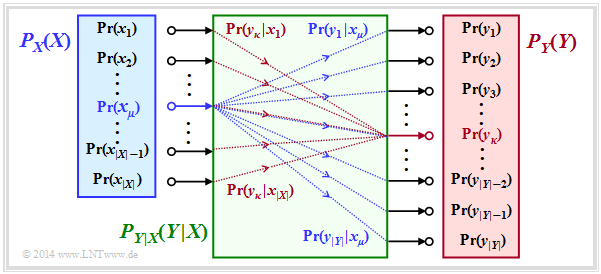
The entropies defined so far in general terms are now applied to digital signal transmission, whereby we assume a discrete memoryless channel $\rm (DMC)$ according to the graphic:
- The set of source symbols is characterised by the discrete random variable $X$ , where $|X|$ indicates the source symbol set size:
- $$X = \{\hspace{0.05cm}x_1\hspace{0.05cm}, \hspace{0.15cm} x_2\hspace{0.05cm},\hspace{0.15cm} \text{...}\hspace{0.1cm} ,\hspace{0.15cm} x_{\mu}\hspace{0.05cm}, \hspace{0.15cm}\text{...}\hspace{0.1cm} , \hspace{0.15cm} x_{|X|}\hspace{0.05cm}\}\hspace{0.05cm}.$$
- Correspondingly, $Y$ characterises the set of sink symbols with the symbol set size $|Y|$:
- $$Y = \{\hspace{0.05cm}y_1\hspace{0.05cm}, \hspace{0.15cm} y_2\hspace{0.05cm},\hspace{0.15cm} \text{...}\hspace{0.1cm} ,\hspace{0.15cm} y_{\kappa}\hspace{0.05cm}, \hspace{0.15cm}\text{...}\hspace{0.1cm} , \hspace{0.15cm} Y_{|Y|}\hspace{0.05cm}\}\hspace{0.05cm}.$$
- Usually $|Y| = |X|$is valid. Also possible is $|Y| > |X|$, for example with the Binary Erasure Channel (BEC):
- $$X = \{0,\ 1\},\hspace{0.5cm} Y = \{0,\ 1,\ \ \text{E}\}\ ⇒ \ |X| = 2, \ |Y| = 3.$$
- The sink symbol $\rm E$ indicates an "erasure". The event $Y=\text{E}$ indicates that a decision for $0$ or for $1$ would be too uncertain.
- The symbol probabilities of the source and sink are accounted for in the graph by the probability mass functions $P_X(X)$ and $P_Y(Y)$:
- $$P_X(x_{\mu}) = {\rm Pr}( X = x_{\mu})\hspace{0.05cm}, \hspace{0.3cm} P_Y(y_{\kappa}) = {\rm Pr}( Y = y_{\kappa})\hspace{0.05cm}.$$
- Let it hold: The prtobability mass functions $P_X(X)$ and $P_Y(Y)$ contain no zeros ⇒ $\text{supp}(P_X) = P_X$ and $\text{supp}(P_Y) = P_Y$. This prerequisite facilitates the description without loss of generality.
- All transition probabilities of the discrete memoryless channel $\rm (DMC)$ are captured by the conditional probability function $P_{Y|X}(Y|X)$. . With $x_μ ∈ X$ and $y_κ ∈ Y$, the following definition applies to this:
- $$P_{Y\hspace{0.01cm}|\hspace{0.01cm}X}(y_{\kappa}\hspace{0.01cm} |\hspace{0.01cm} x_{\mu}) = {\rm Pr}(Y\hspace{-0.1cm} = y_{\kappa}\hspace{0.03cm} | \hspace{0.03cm}X \hspace{-0.1cm}= x_{\mu})\hspace{0.05cm}.$$
The green block in the graph marks $P_{Y|X}(⋅)$ with $|X|$ inputs and $|Y|$ outputs. Blue connections mark transition probabilities $\text{Pr}(y_i | x_μ)$ starting from $x_μ$ with $1 ≤ i ≤ |Y|$, while all red connections end at $y_κ$: $\text{Pr}(y_κ | x_i)$ with $1 ≤ i ≤ |X|$.
Before we give the entropies for the individual probability functions, viz.
- $$P_X(X) ⇒ H(X),\hspace{0.5cm} P_Y(Y) ⇒ H(Y), \hspace{0.5cm} P_{XY}(X) ⇒ H(XY), \hspace{0.5cm} P_{Y|X}(Y|X) ⇒ H(Y|X),\hspace{0.5cm} P_{X|Y}(X|Y) ⇒ H(X|Y),$$
the above statements are to be illustrated by an example.
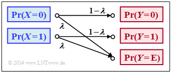
$\text{Example 1}$: In the book "Channel Coding" we also deal with the Binary Erasure Channel $\rm (BEC)$, which is sketched in a somewhat modified form on the right. The following prerequisites apply:
- Let the input alphabet be binary ⇒ $X = \{0,\ 1 \}$ ⇒ $\vert X\vert = 2$ while three values are possible at the output ⇒ $Y = \{0,\ 1,\ \text{E} \}$ ⇒ $\vert Y\vert = 3$.
- The symbol $\text{E}$ indicates the case that the receiver cannot decide for one of the binary symbols $0$ or $1$ due to too much channel interference. "E" stands for erasure.
- With the $\rm BEC$ according to the above sketch, both a transmitted $0$ and a $1$ are erased with probability $λ$ while the probability of a correct transmission is $1 – λ$ in each case.
- In contrast, transmission errors are excluded by the BEC model
⇒ the conditional probabilities $\text{Pr}(Y = 1 \vert X = 0)$ and $\text{Pr}(Y = 0 \vert X = 1)$ are both zero.
At the transmitter, the "zeros" and "ones" would not necessarily be equally probable. Rather, we use the probability mass functions
- $$\begin{align*}P_X(X) & = \big ( {\rm Pr}( X = 0)\hspace{0.05cm},\hspace{0.2cm} {\rm Pr}( X = 1) \big )\hspace{0.05cm},\\ P_Y(Y) & = \big ( {\rm Pr}( Y = 0)\hspace{0.05cm},\hspace{0.2cm} {\rm Pr}( Y = 1)\hspace{0.05cm},\hspace{0.2cm} {\rm Pr}( Y = {\rm E}) \big )\hspace{0.05cm}.\end{align*}$$
From the above model we then get:
- $$\begin{align*}P_Y(0) & = {\rm Pr}( Y \hspace{-0.1cm} = 0) = P_X(0) \cdot ( 1 - \lambda)\hspace{0.05cm}, \\ P_Y(1) & = {\rm Pr}( Y \hspace{-0.1cm} = 1) = P_X(1) \cdot ( 1 - \lambda)\hspace{0.05cm}, \\ P_Y({\rm E}) & = {\rm Pr}( Y \hspace{-0.1cm} = {\rm E}) = P_X(0) \cdot \lambda \hspace{0.1cm}+\hspace{0.1cm} P_X(1) \cdot \lambda \hspace{0.05cm}.\end{align*}$$
If we now take $P_X(X)$ and $P_Y(Y)$ to be vectors, the result can be represented as follows:
- $$P_{\hspace{0.05cm}Y}(Y) = P_X(X) \cdot P_{\hspace{0.05cm}Y\hspace{-0.01cm}\vert \hspace{-0.01cm}X}(Y\hspace{-0.01cm} \vert \hspace{-0.01cm} X) \hspace{0.05cm},$$
where the transition probabilities $\text{Pr}(y_κ\vert x_μ)$ are accounted for by the following matrix:
- $$P_{\hspace{0.05cm}Y\hspace{-0.01cm} \vert \hspace{-0.01cm}X}(Y\hspace{-0.01cm} \vert \hspace{-0.01cm} X) = \begin{pmatrix} 1 - \lambda & 0 & \lambda\\ 0 & 1 - \lambda & \lambda \end{pmatrix}\hspace{0.05cm}.$$
Note:
- We have chosen this representation only to simplify the description.
- $P_X(X)$ and $P_Y(Y)$ are not vectors in the true sense and $P_{Y \vert X}(Y\vert X)$ is not a matrix either.
Directional diagram for digital signal transmission
All entropies defined in the last chapter also apply to digital signal transmission. However, it is expedient to choose the right-hand diagram instead of the diagram used so far, corresponding to the left-hand diagram, in which the direction from source $X$ to sink $Y$ is recognisable.
Let us now interpret the right graph starting from the general $\rm DMC$ model:
- The source entropy $H(X)$ denotes the average information content of the source symbol sequence. With the symbol set size $|X|$ applies:
- $$H(X) = {\rm E} \left [ {\rm log}_2 \hspace{0.1cm} \frac{1}{P_X(X)}\right ] \hspace{0.1cm} = -{\rm E} \big [ {\rm log}_2 \hspace{0.1cm}{P_X(X)}\big ] \hspace{0.2cm} =\hspace{0.2cm} \sum_{\mu = 1}^{|X|} P_X(x_{\mu}) \cdot {\rm log}_2 \hspace{0.1cm} \frac{1}{P_X(x_{\mu})} \hspace{0.05cm}.$$
- The equivocation $H(X|Y)$ indicates the average information content that an observer who knows exactly about the sink $Y$ gains by observing the source $X$ :
- $$H(X|Y) = {\rm E} \left [ {\rm log}_2 \hspace{0.1cm} \frac{1}{P_{\hspace{0.05cm}X\hspace{-0.01cm}|\hspace{-0.01cm}Y}(X\hspace{-0.01cm} |\hspace{0.03cm} Y)}\right ] \hspace{0.2cm}=\hspace{0.2cm} \sum_{\mu = 1}^{|X|} \sum_{\kappa = 1}^{|Y|} P_{XY}(x_{\mu},\hspace{0.05cm}y_{\kappa}) \cdot {\rm log}_2 \hspace{0.1cm} \frac{1}{P_{\hspace{0.05cm}X\hspace{-0.01cm}|\hspace{0.03cm}Y} (\hspace{0.05cm}x_{\mu}\hspace{0.03cm} |\hspace{0.05cm} y_{\kappa})} \hspace{0.05cm}.$$
- The equivocation is the portion of the source entropy $H(X)$ that is lost due to channel interference (for digital channel: transmission errors). The mutual information $I(X; Y)$ remains, which reaches the sink:
- $$I(X;Y) = {\rm E} \left [ {\rm log}_2 \hspace{0.1cm} \frac{P_{XY}(X, Y)}{P_X(X) \cdot P_Y(Y)}\right ] \hspace{0.2cm} = H(X) - H(X|Y) \hspace{0.05cm}.$$
- The irrelevance $H(Y|X)$ indicates the average information content that an observer who knows exactly about the source $X$ gains by observing the sink $Y$:
- $$H(Y|X) = {\rm E} \left [ {\rm log}_2 \hspace{0.1cm} \frac{1}{P_{\hspace{0.05cm}Y\hspace{-0.01cm}|\hspace{-0.01cm}X}(Y\hspace{-0.01cm} |\hspace{0.03cm} X)}\right ] \hspace{0.2cm}=\hspace{0.2cm} \sum_{\mu = 1}^{|X|} \sum_{\kappa = 1}^{|Y|} P_{XY}(x_{\mu},\hspace{0.05cm}y_{\kappa}) \cdot {\rm log}_2 \hspace{0.1cm} \frac{1}{P_{\hspace{0.05cm}Y\hspace{-0.01cm}|\hspace{0.03cm}X} (\hspace{0.05cm}y_{\kappa}\hspace{0.03cm} |\hspace{0.05cm} x_{\mu})} \hspace{0.05cm}.$$
- The sink entropy $H(Y)$, the mean information content of the sink. $H(Y)$ is the sum of the useful mutual information $I(X; Y)$ and the useless irrelevance $H(Y|X)$, which comes exclusively from channel errors:
- $$H(Y) = {\rm E} \left [ {\rm log}_2 \hspace{0.1cm} \frac{1}{P_Y(Y)}\right ] \hspace{0.1cm} = -{\rm E} \big [ {\rm log}_2 \hspace{0.1cm}{P_Y(Y)}\big ] \hspace{0.2cm} =I(X;Y) + H(Y|X) \hspace{0.05cm}.$$
Calculation of the mutual information for the binary channel
These definitions will now be illustrated by an example. We deliberately avoid simplifying the calculations by exploiting symmetries.
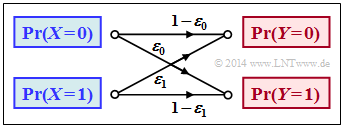
$\text{Example 2}$: We consider the general binary channel without memory according to the sketch. Let the falsification probabilities be:
- $$\begin{align*}\varepsilon_0 & = {\rm Pr}(Y\hspace{-0.1cm} = 1\hspace{0.05cm}\vert X \hspace{-0.1cm}= 0) = 0.01\hspace{0.05cm},\\ \varepsilon_1 & = {\rm Pr}(Y\hspace{-0.1cm} = 0\hspace{0.05cm} \vert X \hspace{-0.1cm}= 1) = 0.2\hspace{0.05cm}\end{align*}$$
- $$\Rightarrow \hspace{0.3cm} P_{\hspace{0.05cm}Y\hspace{-0.01cm} \vert \hspace{-0.01cm}X}(Y\hspace{-0.01cm} \vert \hspace{-0.01cm} X) = \begin{pmatrix} 1 - \varepsilon_0 & \varepsilon_0\\ \varepsilon_1 & 1 - \varepsilon_1 \end{pmatrix} = \begin{pmatrix} 0.99 & 0.01\\ 0.2 & 0.8 \end{pmatrix} \hspace{0.05cm}.$$
Furthermore, we assume source symbols that are not equally probable:
- $$P_X(X) = \big ( p_0,\ p_1 \big )= \big ( 0.1,\ 0.9 \big ) \hspace{0.05cm}.$$
With the binary entropy function $H_{\rm bin}(p)$, we thus obtain for the source entropy:
- $$H(X) = H_{\rm bin} (0.1) = 0.4690 \hspace{0.12cm}{\rm bit} \hspace{0.05cm}.$$
For the probability mass function of the sink as well as for the sink entropy we thus obtain:
- $$P_Y(Y) = \big [ {\rm Pr}( Y\hspace{-0.1cm} = 0)\hspace{0.05cm}, \ {\rm Pr}( Y \hspace{-0.1cm}= 1) \big ] = \big ( p_0\hspace{0.05cm},\ p_1 \big ) \cdot \begin{pmatrix} 1 - \varepsilon_0 & \varepsilon_0\\ \varepsilon_1 & 1 - \varepsilon_1 \end{pmatrix} $$
- $$\begin{align*}\Rightarrow \hspace{0.3cm} {\rm Pr}( Y \hspace{-0.1cm}= 0)& = p_0 \cdot (1 - \varepsilon_0) + p_1 \cdot \varepsilon_1 = 0.1 \cdot 0.99 + 0.9 \cdot 0.2 = 0.279\hspace{0.05cm},\\ {\rm Pr}( Y \hspace{-0.1cm}= 1) & = 1 - {\rm Pr}( Y \hspace{-0.1cm}= 0) = 0.721\end{align*}$$
- $$\Rightarrow \hspace{0.3cm} H(Y) = H_{\rm bin} (0.279) = 0.8541 \hspace{0.12cm}{\rm bit} \hspace{0.05cm}. $$
The joint probabilities $p_{\mu \kappa} = \text{Pr}\big[(X = μ) ∩ (Y = κ)\big]$ between source and sink are:
- $$\begin{align*}p_{00} & = p_0 \cdot (1 - \varepsilon_0) = 0.099\hspace{0.05cm},\hspace{0.5cm}p_{01}= p_0 \cdot \varepsilon_0 = 0.001\hspace{0.05cm},\\ p_{10} & = p_1 \cdot (1 - \varepsilon_1) = 0.180\hspace{0.05cm},\hspace{0.5cm}p_{11}= p_1 \cdot \varepsilon_1 = 0.720\hspace{0.05cm}.\end{align*}$$
From this one obtains for
- the joint entropy:
- $$H(XY) = p_{00}\hspace{-0.05cm} \cdot \hspace{-0.05cm}{\rm log}_2 \hspace{0.05cm} \frac{1}{p_{00} \rm } + p_{01} \hspace{-0.05cm} \cdot \hspace{-0.05cm}{\rm log}_2 \hspace{0.05cm} \frac{1}{p_{01} \rm } + p_{10}\hspace{-0.05cm} \cdot \hspace{-0.05cm} {\rm log}_2 \hspace{0.05cm} \frac{1}{p_{10} \rm } + p_{11} \hspace{-0.05cm} \cdot \hspace{-0.05cm} {\rm log}_2\hspace{0.05cm} \frac{1}{p_{11}\rm } = 1.1268\,{\rm bit} \hspace{0.05cm},$$
- the mutual information:
- $$I(X;Y) = H(X) + H(Y) - H(XY) = 0.4690 + 0.8541 - 1.1268 = 0.1963\hspace{0.12cm}{\rm bit} \hspace{0.05cm},$$
- the equivocation:
- $$H(X \vert Y) \hspace{-0.01cm} =\hspace{-0.01cm} H(X) \hspace{-0.01cm} -\hspace{-0.01cm} I(X;Y) \hspace{-0.01cm} $$
- $$\Rightarrow \hspace{0.3cm} H(X \vert Y) \hspace{-0.01cm} = \hspace{-0.01cm} 0.4690\hspace{-0.01cm} -\hspace{-0.01cm} 0.1963\hspace{-0.01cm} =\hspace{-0.01cm} 0.2727\hspace{0.12cm}{\rm bit} \hspace{0.05cm},$$
- the irrelevance:
- $$H(Y \vert X) = H(Y) - I(X;Y) $$
- $$\Rightarrow \hspace{0.3cm} H(Y \vert X) = 0.8541 - 0.1963 = 0.6578\hspace{0.12cm}{\rm bit} \hspace{0.05cm}.$$
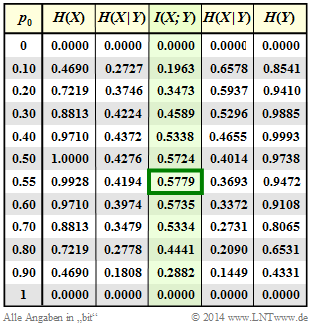
The results are summarised in the graph.
Notes:
- The equivocation and irrelevance could also have been calculated directly (but with extra effort) from the corresponding probability functions.
- For example, the irrelevance:
- $$H(Y|X) = \hspace{-0.2cm} \sum_{(x, y) \hspace{0.05cm}\in \hspace{0.05cm}XY} \hspace{-0.2cm} P_{XY}(x,\hspace{0.05cm}y) \cdot {\rm log}_2 \hspace{0.1cm} \frac{1}{P_{\hspace{0.05cm}Y\hspace{-0.01cm}|\hspace{0.03cm}X} (\hspace{0.05cm}y\hspace{0.03cm} |\hspace{0.05cm} x)}= p_{00} \cdot {\rm log}_2 \hspace{0.1cm} \frac{1}{1\hspace{-0.08cm} - \hspace{-0.08cm}\varepsilon_0} + p_{01} \cdot {\rm log}_2 \hspace{0.1cm} \frac{1}{\varepsilon_0} + p_{10} \cdot {\rm log}_2 \hspace{0.1cm} \frac{1}{1\hspace{-0.08cm} - \hspace{-0.08cm}\varepsilon_1} + p_{11} \cdot {\rm log}_2 \hspace{0.1cm} \frac{1}{\varepsilon_1} = 0.6578\,{\rm bit} \hspace{0.05cm}.$$
Definition and meaning of channel capacity
We further consider a discrete memoryless channel $\rm (DMC)$ with a finite number of source symbols ⇒ $|X|$ and also only finitely many sink symbols ⇒ $|Y|$, as shown in the first section of this chapter.
- If one calculates the mutual information $I(X, Y)$ as explained in $\text{Example 2}$, it also depends on the source statistic ⇒ $P_X(X)$.
- Ergo: The mutual information $I(X, Y)$ is not a pure channel characteristic.
$\text{Definition:}$ The channel capacity introduced by Claude E. Shannon according to his standard work [Sha48][1] reads:
- $$C = \max_{P_X(X)} \hspace{0.15cm} I(X;Y) \hspace{0.05cm}.$$
The additional unit "bit/use" is often added. Since according to this definition the best possible source statistics are always the basis:
- $C$ depends only on the channel properties ⇒ $P_{Y \vert X}(Y \vert X)$,
- but not on the source statistics ⇒ $P_X(X)$.
Shannon needed the quantity $C$ to formulate the "Channel Coding Theorem" – one of the highlights of the information theory he founded.
$\text{Shannon's Channel Coding Theorem: }$
- For every transmission channel with channel capacity $C > 0$, there exists (at least) one $(k,\ n)$–block code, whose (block) error probability approaches zero as long as the code rate $R = k/n$ is less than or equal to the channel capacity:
- $$R ≤ C.$$
- The prerequisite for this, however, is that the following applies to the block length of this code: $n → ∞.$
The proof of this theorem, which is beyond the scope of our learning tutorial, can be found for example in [CT06][2], [Kra13][3] und [Meck09][4].
As will be shown in Exercise 3.13, the reverse is also true. This proof can also be found in the literature references just mentioned.
$\text{Reverse of Shannon's channel coding theorem: }$
If the rate $R$ of the $(n,\ k)$–block code used is greater than the channel capacity $C$, then an arbitrarily small block error probability is not achievable.
In the chapter AWGN model for discrete-time band-limited signals it is explained in connection with the continuous AWGN channel model what phenomenally great significance Shannon's theorem has for the entire field of information technology, not only for those interested exclusively in theory, but also for practitioners.
Channel capacity of a binary channel
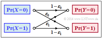
The mutual information of the general (asymmetrical) binary channel according to this sketch was calculated in $\text{Example 2}$. In this model, the input symbols $0$ and $1$ are distorted to different degrees:
- $$P_{\hspace{0.05cm}Y\hspace{-0.01cm}|\hspace{-0.01cm}X}(Y\hspace{-0.01cm} |\hspace{-0.01cm} X) = \begin{pmatrix} 1 - \varepsilon_0 & \varepsilon_0\\ \varepsilon_1 & 1 - \varepsilon_1 \end{pmatrix} \hspace{0.05cm}.$$
The mutual information can be represented with the probability mass function $P_X(X) = (p_0,\ p_1)$ as follows:
- $$I(X ;Y) = \sum_{\mu = 1}^{2} \hspace{0.1cm}\sum_{\kappa = 1}^{2} \hspace{0.2cm} {\rm Pr} (\hspace{0.05cm}y_{\kappa}\hspace{0.03cm} |\hspace{0.05cm} x_{\mu}) \cdot {\rm Pr} (\hspace{0.05cm}x_{\mu}\hspace{0.05cm})\cdot {\rm log}_2 \hspace{0.1cm} \frac{{\rm Pr} (\hspace{0.05cm}y_{\kappa}\hspace{0.03cm} |\hspace{0.05cm} x_{\mu})}{{\rm Pr} (\hspace{0.05cm}y_{\kappa})} $$
- $$\begin{align*}\Rightarrow \hspace{0.3cm} I(X ;Y) &= \hspace{-0.01cm} (1 \hspace{-0.08cm}- \hspace{-0.08cm}\varepsilon_0) \cdot p_0 \cdot {\rm log}_2 \hspace{0.1cm} \frac{1 \hspace{-0.08cm}- \hspace{-0.08cm}\varepsilon_0}{(1 \hspace{-0.08cm}- \hspace{-0.08cm}\varepsilon_0) \cdot p_0 + \varepsilon_1 \cdot p_1} + \varepsilon_0 \cdot p_0 \cdot {\rm log}_2 \hspace{0.1cm} \frac{\varepsilon_0}{(1 \hspace{-0.08cm}- \hspace{-0.08cm}\varepsilon_0) \cdot p_0 + \varepsilon_1 \cdot p_1} \ + \\ & + \hspace{-0.01cm} \varepsilon_1 \cdot p_1 \cdot {\rm log}_2 \hspace{0.1cm} \frac{\varepsilon_1}{\varepsilon_0 \cdot p_0 + (1 \hspace{-0.08cm}- \hspace{-0.08cm}\varepsilon_1) \cdot p_1} + (1 \hspace{-0.08cm}- \hspace{-0.08cm}\varepsilon_1) \cdot p_1 \cdot {\rm log}_2 \hspace{0.1cm} \frac{1 \hspace{-0.08cm}- \hspace{-0.08cm}\varepsilon_1}{\varepsilon_0 \cdot p_0 + (1 \hspace{-0.08cm}- \hspace{-0.08cm}\varepsilon_1) \cdot p_1} \hspace{0.05cm}.\end{align*}$$
$\text{Example 3}$: In the following we set $ε_0 = 0.01$ and $ε_1 = 0.2$.
Column 4 of the adjacent table shows (highlighted in green) the mutual information $I(X; Y)$ of this asymmetrical binary channel depending on the source symbol probability $p_0 = {\rm Pr}(X = 0)$ . One can see:
- The mutual information depends on the symbol probabilities $p_0$ and $p_1 = 1 - p_0$.
- Here the maximum value of $I(X; Y)$ results in $p_0 ≈ 0.55$ ⇒ $p_1 ≈ 0.45$.
- The result $p_0 > p_1$ follows from the relation $ε_0 < ε_1$ (the "zero" is less distorted).
- The capacity of this channel is $C = 0.5779 \ \rm bit/use$.
In the above equation, the Binary Symmetric Channel $\rm (BSC)$ with parameters $ε = ε_0 = ε_1$ is also included as a special case. Hints:
- In Exercise 3.10 the mutual information of the BSC is calculated for the system parameters $ε = 0.1$ and $p_0 = 0.2$ .
- In Exercise 3.10Z its channel capacity is given as follows:
- $$C_{\rm BSC} = 1 - H_{\rm bin} (\varepsilon) \hspace{0.05cm}.$$
Properties of symmetrical channels
The capacity calculation of the (general) discrete memoryless channel $\rm (DMC)$ is often complex. It simplifies decisively if symmetries of the channel are exploited.
The diagram shows two examples:
- In the case of the uniformly dispersive channel all source symbols $x ∈ X$ result in exactly the same set of transition probabilities ⇒ $\{P_{Y\hspace{0.03cm}|\hspace{0.01cm}X}(y_κ\hspace{0.05cm}|\hspace{0.05cm}x)\}$ with $1 ≤ κ ≤ |Y|$. Here $q + r + s = 1$ must always apply here (see left graph).
- In the case of the uniformly focusing channel , the same set of transition probabilities ⇒ $\{P_{Y\hspace{0.03cm}|\hspace{0.01cm}X}(y\hspace{0.05cm}|\hspace{0.05cm}x_μ)\}$ with $1 ≤ μ ≤ |X|$ results for all sink symbols $y ∈ Y$ . Here, $t + u + v = 1$ need not necessarily hold (see right graph).
$\text{Definition:}$ If a discrete memoryless channel is both uniformly dispersive and uniformly focussing, it is a strictly symmetric channel.
- With an equally distributed source alphabet, this channel has the capacity
- $$C = {\rm log}_2 \hspace{0.1cm} \vert Y \vert + \sum_{y \hspace{0.05cm}\in\hspace{0.05cm} Y} \hspace{0.1cm} P_{\hspace{0.03cm}Y \vert \hspace{0.01cm} X}(y\hspace{0.05cm} \vert \hspace{0.05cm}x) \cdot {\rm log}_2 \hspace{0.1cm}P_{\hspace{0.01cm}Y \vert \hspace{0.01cm} X}(y\hspace{0.05cm}\vert\hspace{0.05cm} x) \hspace{0.05cm}.$$
- Any $x ∈ X$ can be used for this equation.
This definition will now be clarified by an example.
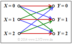
$\text{Example 4}$: In the channel under consideration, there are connections between all $ \vert X \vert = 3$ inputs and all $ \vert Y \vert = 3$ outputs:
- A red connection stands for $P_{Y \hspace{0.03cm}\vert\hspace{0.01cm} X}(y_κ \hspace{0.05cm} \vert \hspace{0.05cm} x_μ) = 0.7$.
- A blue connection stands for $P_{Y \hspace{0.03cm}\vert\hspace{0.01cm} X}(y_κ \hspace{0.05cm}\vert \hspace{0.05cm} x_μ) = 0.2$.
- A green connection stands for $P_{Y \hspace{0.03cm}\vert\hspace{0.01cm} X}(y_κ \hspace{0.05cm}\vert\hspace{0.05cm} x_μ) = 0.1$.
According to the above equation, the following applies to the channel capacity:
- $$C = {\rm log}_2 \hspace{0.1cm} (3) + 0.7 \cdot {\rm log}_2 \hspace{0.1cm} (0.7) + 0.2 \cdot {\rm log}_2 \hspace{0.1cm} (0.2) + 0.1 \cdot {\rm log}_2 \hspace{0.1cm} (0.1) = 0.4282 \,\,{\rm bit} \hspace{0.05cm}.$$
Notes:
- The addition of "the same set of transition probabilities” in the above definitions does not mean that it must apply:
- $$P_{Y \hspace{0.03cm}\vert\hspace{0.01cm} X}(y_κ \hspace{0.05cm}\vert\hspace{0.05cm} x_1) = P_{Y \hspace{0.03cm}\vert\hspace{0.01cm} X}(y_κ \hspace{0.05cm}\vert\hspace{0.05cm} x_2) = P_{Y \hspace{0.03cm}\vert\hspace{0.01cm} X}(y_κ \hspace{0.05cm}\vert\hspace{0.05cm} x_3).$$
- Rather, here a red, a blue and a green arrow leaves from each input and a red, a blue and a green arrow arrives at each output.
- The respective sequences permute: R – G – B, B – R – G, G – B – R.
An example of a strictly symmetrical channel is the Binary Symmetric Channel $\rm (BSC)$. In contrast, the Binary Erasure Channel $\rm (BEC)$ is not strictly symmetric, because,
- although it is uniformly dispersive,
- but it is not uniformly focussing.
The following definition is less restrictive than the previous one of a strictly symmetric channel.
$\text{Definition:}$ A symmetric channel exists,
- if it can be divided into several $($generally $L)$ strongly symmetrical sub-channels,
- by splitting the output alphabet $Y$ into $L$ subsets $Y_1$, ... , $Y_L$ .
Such a "symmetric channel" has the following capacity:
- $$C = \sum_{l \hspace{0.05cm}=\hspace{0.05cm} 1}^{L} \hspace{0.1cm} p_{\hspace{0.03cm}l} \cdot C_{\hspace{0.03cm}l} \hspace{0.05cm}.$$
The following designations are used here:
- $p_{\hspace{0.03cm}l}$ indicates the probability that the $l$–th sub-channel is selected.
- $C_{\hspace{0.03cm}l}$ is the channel capacity of this $l$–th sub-channel.
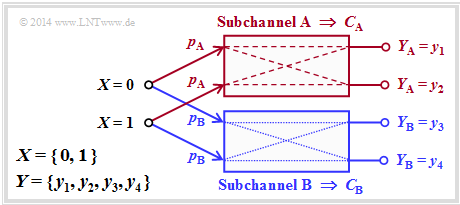
The diagram illustrates this definition for $L = 2$ with the sub-channels $\rm A$ and $\rm B$.
- The differently drawn transitions (dashed or dotted) show that the two sub-channels can be different, so that $C_{\rm A} ≠ C_{\rm B}$ will generally apply.
- For the capacity of the total channel one thus obtains in general:
- $$C = p_{\rm A} \cdot C_{\rm A} + p_{\rm B} \cdot C_{\rm B} \hspace{0.05cm}.$$
- No statement is made here about the structure of the two sub-channels.
The following example will show that the "Binary Erasure Channel" $\rm (BEC)$ can also be described in principle by this diagram. However, the two output symbols $y_3$ and $y_4$ must then be combined into a single symbol.
$\text{Example 5}$: The left figure shows the usual representation of the Binary Erasure Channel $\rm (BEC)$ with input $X = \{0,\ 1\}$ and output $Y = \{0,\ 1,\ \text{E} \}$.
If one divides this according to the right grafic into
- an "ideal channel" $(y = x)$ for
- $$y ∈ Y_{\rm A} = \{0, 1\} \ \ ⇒ \ \ C_{\rm A} = 1 \ \rm bit/use,$$
- an "erasure channel" $(y = {\rm E})$ for
- $$y ∈ Y_{\rm B} = \{\rm E \} \ \ ⇒ \ \ C_{\rm B} = 0,$$
then we get with the sub-channel weights $p_{\rm A} = 1 – λ$ and $p_{\rm B} = λ$:
- $$C_{\rm BEC} = p_{\rm A} \cdot C_{\rm A} = 1 - \lambda \hspace{0.05cm}.$$
Both channels are strongly symmetrical. The following applies equally for the (ideal) channel $\rm A$
- for $X = 0$ and $X = 1$: $\text{Pr}(Y = 0 \hspace{0.05cm}\vert \hspace{0.05cm} X) = \text{Pr}(Y = 1 \hspace{0.05cm} \vert\hspace{0.05cm} X) = 1 - λ$ ⇒ uniformly dispersive,
- for $Y = 0$ and $Y = 1$: $\text{Pr}(Y \hspace{0.05cm} \vert \hspace{0.05cm} X= 0) = Pr(Y \hspace{0.05cm}\vert\hspace{0.05cm} X = 1) = 1 - λ$ ⇒ uniformly focussing.
The same applies to the erasure channel $\rm B$.
In Exercise 3.12 it will be shown that the capacity of the Binary Symmetric Error & Erasure Channel $\rm (BSEC)$ model can be calculated in the same way. One obtains:
- $$C_{\rm BSEC} = (1- \lambda) \cdot \left [ 1 - H_{\rm bin}(\frac{\varepsilon}{1- \lambda}) \right ]$$
- with the crossover probability $ε$
- and the erasure probability $λ$.
Some basics of channel coding
In order to interpret the channel coding theorem correctly, some basics of channel coding. This extremely important area of Communications Engineering is covered in our learning tutorial $\rm LNTwww$ in a separate book called Channel Coding.
The following description refers to the highly simplified model for binary block codes:
- The infinitely long source symbol sequence $\underline{u}$ (not shown here) is divided into blocks of $k$ bits. We denote the information block with the serial number $j$ by $\underline{u}_j^{(k)}$.
- Each information block $\underline{u}_j^{(k)}$ is converted into a code word $\underline{x}_j^{(n)}$ by the channel encoder with a yellow background, where $n > k$ is to apply. The ratio $R = k/n$ is called the code rate.
- The "Discrete Memoryless Channel" $\rm (DMC)$ is taken into account by transition probabilities $P_{Y\hspace{0.03cm}|\hspace{0.03cm}X}(⋅)$ . This block with a green background causes errors at the bit level. The following can therefore apply: $y_{j, \hspace{0.03cm}i} ≠ x_{j,\hspace{0.03cm} i}$.
- Thus the received blocks $\underline{y}_j^{(n)}$ consisting of $n$ bits can also differ from the code words $\underline{x}_j^{(n)}$ . Likewise, the following generally applies to the blocks after the decoder:
- $$\underline{v}_j^{(k)} ≠ \underline{u}_j^{(k)}.$$
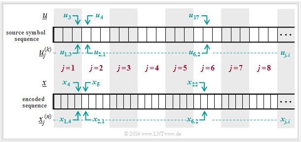
$\text{Example 6}$: The diagram is intended to illustrate the nomenclature used here using the example of $k = 3$ and $n = 4$. The first eight blocks of the information sequence $\underline{u}$ and the encoded sequence $\underline{x}$ are shown.
One can see the following assignment between the blocked and the unblocked description:
- Bit 3 of the 1st information block ⇒ $u_{1,\hspace{0.08cm} 3}$ corresponds to the symbol $u_3$ in unblocked representation.
- Bit 1 of the 2nd information block ⇒ $u_{2, \hspace{0.08cm}1}$ corresponds to the symbol $u_4$ in unblocked representation.
- Bit 2 of the 6th information block ⇒ $u_{6, \hspace{0.08cm}2}$ corresponds to the symbol $u_{17}$ in unblocked representation.
- Bit 4 of the 1st code word ⇒ $x_{1, \hspace{0.08cm}4}$ corresponds to the symbol $x_4$ in unblocked representation.
- Bit 1 of the 2nd code word ⇒ $x_{2, \hspace{0.08cm}1}$ corresponds to the symbol $x_5$ in unblocked representation.
- Bit 2 of the 6th code word ⇒ $x_{6, \hspace{0.08cm}2}$ corresponds to the symbol $x_{22}$ in unblocked representation.
Relationship between block errors and bit errors
To interpret the channel coding theorem, we still need various definitions for error probabilities. Various descriptive variables can be derived from the above system model:
$\text{Definitions:}$
- In the present channel model, the $\text{channel error probability}$ is given by
- $$\text{Pr(channel error)} = {\rm Pr} \left ({y}_{j,\hspace{0.05cm} i} \ne {x}_{j,\hspace{0.05cm} i} \right )\hspace{0.05cm}.$$
- For example, in the BSC model $\text{Pr(channel error)} = ε$ für alle $j = 1, 2$, ... and $1 ≤ i ≤ n$.
- The $\text{block error probability}$ refers to the allocated information blocks at the encoder input ⇒ $\underline{u}_j^{(k)}$ and the decoder output ⇒ $\underline{v}_j^{(k)}$, each in blocks of $k$ bits:
- $$\text{Pr(block error)} = {\rm Pr} \left (\underline{\upsilon}_j^{(k)} \ne \underline{u}_j^{(k)} \right )\hspace{0.05cm}.$$
- The $\text{bit error probability}$ also refers to the input and the output of the entire coding system under consideration, but at the bit level:
- $$\text{Pr(bit error)} = {\rm Pr} \left ({\upsilon}_{j,\hspace{0.05cm} i} \ne {u}_{j,\hspace{0.05cm} i} \right )\hspace{0.05cm}.$$
- For simplicity, it is assumed here that all $k$ bits $u_{j,\hspace{0.08cm}i}$ $(1 ≤ i ≤ k)$ of the information block $j$ are corrupted with equal probability.
- Otherwise, the $k$ bits would have to be averaged.
There is a general relationship between the block error probability and the bit error probability:
- $${1}/{k} \cdot \text{Pr(block error)} \le \text{Pr(bit error)} \le \text{Pr(block error)} \hspace{0.05cm}.$$
- The lower bound results when all bits are wrong in all faulty blocks.
- If there is exactly only one bit error in each faulty block, then the bit error probability is identical to the block error probability:
- $$ \text{Pr(bit error)} \equiv \text{Pr(block error)} \hspace{0.05cm}.$$
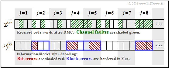
$\text{Example 7:}$ The upper graph shows the first eight reception blocks $\underline{y}_j^{(n)}$ with $n = 4$ bits each. Here channel errors are shaded green.
Below, the initial sequence $\underline{v}$ after decoding is sketched, divided into blocks $\underline{v}_j^{(k)}$ with $k = 3$ bits each. Note:
- Bit errors are shaded red in the lower diagram.
- Block errors can be recognised by the blue frame.
For this, some (due to the short sequence) only very vague information about the error probabilities:
- Half of the reception bits are shaded green. From this follows:
- $$\text{Pr(channel error)} = 16/32 = 1/2.$$
- The bit error probability with the exemplary encoding and decoding is:
- $$\text{Pr(bit error)} = 8/24 = 1/3.$$
- In contrast, with uncoded transmission would be:
- $$\text{Pr(bit error)} = {\rm Pr(Kanalfehler)} = 1/2.$$
- Half of the decoded blocks are outlined in blue. From this follows:
- $$\text{Pr(block error)} = 4/8 = 1/2.$$
- With $\text{Pr(block error)}= 1/2$ and $k = 3$ the bit error probability is in the following range:
- $$1/6 \le \text{Pr(bit error)} \le 1/2 \hspace{0.05cm}.$$
- The upper bound with respect to bit errors is obtained when all bits in each of the four corrupted blocks are wrong: $\text{Pr(bit error)} = 12/24 = 1/2.$
- The lower bound indicates that only one bit is wrong in each of the four corrupted blocks: $\text{Pr(bit error)} = 4/24 = 1/6$.
Rate, channel capacity and bit error probability
$\text{Basically:}$
- Channel coding increases the reliability of data transmission from the source to the sink.
- If the code rate $R = k/n$ is reduced and the added redundancy $(1 - R)$ is increased, the data reliability is generally improved and the bit error probability is reduced, which we will refer to as $p_{\rm B}$ in the following:
- $$p_{\rm B} = \text{Pr(bit error)} = {\rm Pr} \left ({\upsilon}_{j,\hspace{0.05cm} i} \ne {u}_{j,\hspace{0.05cm} i} \right )\hspace{0.05cm}.$$
The following theorem is based on the "Data Processing Theorem" and "Fano's Lemma". The derivation can be found in standard works on information theory, for example in [CT06][2]:
$\text{Inversion of Shannon's Channel Coding Theorem:}$
If one uses a channel with too small a capacity $R$ for data transmission at rate $C < R$, the bit error probability $p_{\rm B}$ cannot fall below a lower bound even with the best possible channel coding:
- $$p_{\rm B} \ge H_{\rm bin}^{-1} \cdot \left ( 1 - {C}/{R}\right ) > 0\hspace{0.05cm}.$$
Here $H_{\rm bin}(⋅)$ denotes the binary entropy function.
Since the probability of the block errors can never be smaller than that of the bit errors, the block error probability „zero” is also not possible for $R > C$ .
From the given bounds for the bit errors,
- $$ {1}/{k} \cdot {\rm Pr}({\rm block error}) \le {\rm Pr}({\rm bit error}) \le {\rm Pr}({\rm block error})\hspace{0.05cm},$$
a range for the block error probability can also be given:
- $$ {\rm Pr}({\rm bit error}) \le {\rm Pr}({\rm block error}) \le k \cdot {\rm Pr}({\rm bit error})\hspace{0.05cm}.$$
$\text{Example 8:}$ For a channel with capacity $C = 1/3$ (bit), error-free data transmission $(p_{\rm B} = 0)$ with code rate $R < 1/3$ is possible in principle.
- However, from the channel coding theorem the special $(k$, $n)$–block code is not known which makes this desired result possible. Shannon also makes no statements on this.
- All that is known is that such a best possible code works with blocks of infinite length. For a given code rate $R = k/n$ both $k → ∞$ and $n → ∞$ thus apply.
- The statement "The bit error probability is zero" is not the same as "No bit errors occur": Even with a finite number of bit errors and $k → ∞$ ⇒ $p_{\rm B} = 0$.
With the code rate $R = 1 > C$ (uncoded transmission) one obtains:
- $$p_{\rm B} \ge H_{\rm bin}^{-1} \cdot \left ( 1 - \frac{1/3}{1}\right ) = H_{\rm bin}^{-1}(2/3) \approx 0.174 > 0\hspace{0.05cm}.$$
With the code rate $R = 1/2 > C$ , the bit error probability is smaller but also different from zero:
- $$p_{\rm B} \ge H_{\rm bin}^{-1} \cdot \left ( 1 - \frac{1/3}{1/2}\right ) = H_{\rm bin}^{-1}(1/3) \approx 0.062 > 0\hspace{0.05cm}.$$
Exercises for the chapter
Exercise 3.10: Mutual Information at the BSC
Exercise 3.10Z: BSC Channel Capacity
Exercise 3.11: Erasure Channel
Exercise 3.11Z: Extremely Asymmetrical Channel
Exercise 3.12: Strictly Symmetrical Channels
Exercise 3.13: Code Rate and Reliability
Exercise 3.14: Channel Coding Theorem
Exercise 3.15: Data Processing Theorem
References
- ↑ Shannon, C.E.: A Mathematical Theory of Communication. In: Bell Syst. Techn. J. 27 (1948), S. 379-423 und S. 623-656.
- ↑ 2.0 2.1 Cover, T.M.; Thomas, J.A.: Elements of Information Theory. West Sussex: John Wiley & Sons, 2nd Edition, 2006.
- ↑ Kramer, G.: Information Theory. Lecture manuscript, Chair of Communications Engineering, Technische Universität München, 2013.
- ↑ Mecking, M.: Information Theory. Lecture manuscript, Chair of Communications Engineering, Technische Universität München, 2009.
