Difference between revisions of "Information Theory/Application to Digital Signal Transmission"
| Line 289: | Line 289: | ||
*In the case of the ''uniformly dispersive channel'' all source symbols $x ∈ X$ result in exactly the same set of transition probabilities ⇒ $\{P_{Y\hspace{0.03cm}|\hspace{0.01cm}X}(y_κ\hspace{0.05cm}|\hspace{0.05cm}x)\}$ with $1 ≤ κ ≤ |Y|$. For the values $q$, $r$, $s$ , $q + r + s = 1$ must always apply here (left graph). | *In the case of the ''uniformly dispersive channel'' all source symbols $x ∈ X$ result in exactly the same set of transition probabilities ⇒ $\{P_{Y\hspace{0.03cm}|\hspace{0.01cm}X}(y_κ\hspace{0.05cm}|\hspace{0.05cm}x)\}$ with $1 ≤ κ ≤ |Y|$. For the values $q$, $r$, $s$ , $q + r + s = 1$ must always apply here (left graph). | ||
| − | *In the case of the ''uniformly focusing channel'' , the same set of transition probabilities ⇒ $\{P_{Y\hspace{0.03cm}|\hspace{0.01cm}X}(y\hspace{0.05cm}|\hspace{0.05cm}x_μ)\}$ with $1 ≤ μ ≤ |X|$ results for all sink symbols $y ∈ Y$ . Here, $t + u + v = 1$ need<u>not</u> necessarily hold (right graph). | + | *In the case of the ''uniformly focusing channel'' , the same set of transition probabilities ⇒ $\{P_{Y\hspace{0.03cm}|\hspace{0.01cm}X}(y\hspace{0.05cm}|\hspace{0.05cm}x_μ)\}$ with $1 ≤ μ ≤ |X|$ results for all sink symbols $y ∈ Y$ . Here, $t + u + v = 1$ need <u>not</u> necessarily hold (right graph). |
[[File:P_ID2793__Inf_T_3_3_S6a.png|center|frame|Examples of symmetrical channels]] | [[File:P_ID2793__Inf_T_3_3_S6a.png|center|frame|Examples of symmetrical channels]] | ||
{{BlaueBox|TEXT= | {{BlaueBox|TEXT= | ||
| − | $\text{Definition:}$ | + | $\text{Definition:}$ If a discrete memoryless channel is both uniformly dispersive and uniformly focussing, it is a '''strongly symmetric channel''' vor. With an equally distributed source alphabet, this has the capacity |
:$$C = {\rm log}_2 \hspace{0.1cm} \vert Y \vert + \sum_{y \hspace{0.05cm}\in\hspace{0.05cm} Y} \hspace{0.1cm} P_{\hspace{0.03cm}Y \vert \hspace{0.01cm} X}(y\hspace{0.05cm} \vert \hspace{0.05cm}x) \cdot | :$$C = {\rm log}_2 \hspace{0.1cm} \vert Y \vert + \sum_{y \hspace{0.05cm}\in\hspace{0.05cm} Y} \hspace{0.1cm} P_{\hspace{0.03cm}Y \vert \hspace{0.01cm} X}(y\hspace{0.05cm} \vert \hspace{0.05cm}x) \cdot | ||
{\rm log}_2 \hspace{0.1cm}P_{\hspace{0.01cm}Y \vert \hspace{0.01cm} X}(y\hspace{0.05cm}\vert\hspace{0.05cm} x) | {\rm log}_2 \hspace{0.1cm}P_{\hspace{0.01cm}Y \vert \hspace{0.01cm} X}(y\hspace{0.05cm}\vert\hspace{0.05cm} x) | ||
\hspace{0.05cm}.$$ | \hspace{0.05cm}.$$ | ||
| − | + | Any $x ∈ X$ can be used for this equation.}} | |
| − | + | This definition will now be clarified by an example. | |
| − | [[File:P_ID2794__Inf_T_3_3_S6b.png|right|frame| | + | [[File:P_ID2794__Inf_T_3_3_S6b.png|right|frame|Strongly symmetrical channel $\vert X \vert = \vert Y \vert= 3$]] |
{{GraueBox|TEXT= | {{GraueBox|TEXT= | ||
| − | $\text{ | + | $\text{Example 4}$: In the channel under consideration, there are connections between $ \vert X \vert = 3$ inputs and all $ \vert Y \vert = 3$ outputs: |
| − | * | + | *A red connection stands for $P_{Y \hspace{0.03cm}\vert\hspace{0.01cm} X}(y_κ \hspace{0.05cm} \vert \hspace{0.05cm} x_μ) = 0.7$. |
| − | * | + | *A blue connection stands for $P_{Y \hspace{0.03cm}\vert\hspace{0.01cm} X}(y_κ \hspace{0.05cm}\vert \hspace{0.05cm} x_μ) = 0.2$. |
| − | * | + | *A green connection stands for $P_{Y \hspace{0.03cm}\vert\hspace{0.01cm} X}(y_κ \hspace{0.05cm}\vert\hspace{0.05cm} x_μ) = 0.1$. |
| − | + | According to the above equation, the following then applies to the channel capacity: | |
:$$C = {\rm log}_2 \hspace{0.1cm} (3) + 0.7 \cdot {\rm log}_2 \hspace{0.1cm} (0.7) | :$$C = {\rm log}_2 \hspace{0.1cm} (3) + 0.7 \cdot {\rm log}_2 \hspace{0.1cm} (0.7) | ||
+ 0.2 \cdot {\rm log}_2 \hspace{0.1cm} (0.2) + 0.1 \cdot {\rm log}_2 \hspace{0.1cm} (0.1) = 0.4282 \,\,{\rm bit} \hspace{0.05cm}.$$ | + 0.2 \cdot {\rm log}_2 \hspace{0.1cm} (0.2) + 0.1 \cdot {\rm log}_2 \hspace{0.1cm} (0.1) = 0.4282 \,\,{\rm bit} \hspace{0.05cm}.$$ | ||
<br clear=all> | <br clear=all> | ||
| − | '' | + | ''Notes'': |
| − | * | + | *The addition of „the same set of transition probabilities” does not mean that $P_{Y \hspace{0.03cm}\vert\hspace{0.01cm} X}(y_κ \hspace{0.05cm}\vert\hspace{0.05cm} x_1) = P_{Y \hspace{0.03cm}\vert\hspace{0.01cm} X}(y_κ \hspace{0.05cm}\vert\hspace{0.05cm} x_2) = P_{Y \hspace{0.03cm}\vert\hspace{0.01cm} X}(y_κ \hspace{0.05cm}\vert\hspace{0.05cm} x_3)$ gelten muss. |
| − | * | + | *Rather, here a red, a blue and a green arrow leaves from each input and a red, a blue and a green arrow arrives at each output. |
| − | * | + | *The respective sequences permute: R – G – B, B – R – G, G – B – R.}} |
| − | + | An example of a strictly symmetrical channel is the [[Channel_Coding/Signal_classification#/media/File:P_ID2341_KC_T_1_2_S2_v2.png|Binary Symmetric Channel]] $\rm (BSC)$. In contrast, the [[Channel_Coding/Signal_classification#Binary_Erasure_Channel_.E2.80.93_BEC|Binary Erasure Channel]] $\rm (BEC)$ is not strictly symmetric, | |
| − | * | + | *because, although it is uniformly dispersive, |
| − | * | + | *but it is not uniformly focussing. |
| − | + | The following definition is less restrictive than the previous one of a strictly symmetric channel. | |
{{BlaueBox|TEXT= | {{BlaueBox|TEXT= | ||
| − | $\text{Definition:}$ | + | $\text{Definition:}$ A '''symmetric channel'' exists, |
| − | * | + | *if it can be divided into several $($generally $L)$ strongly symmetrical sub-channels, |
| − | * | + | *by splitting the output alphabet $Y$ into $L$ subsetsn $Y_1$, ... , $Y_L$ . |
| − | + | Such a symmetrical channel has the following capacity: | |
:$$C = \sum_{l \hspace{0.05cm}=\hspace{0.05cm} 1}^{L} \hspace{0.1cm} p_{\hspace{0.03cm}l} \cdot C_{\hspace{0.03cm}l} \hspace{0.05cm}.$$ | :$$C = \sum_{l \hspace{0.05cm}=\hspace{0.05cm} 1}^{L} \hspace{0.1cm} p_{\hspace{0.03cm}l} \cdot C_{\hspace{0.03cm}l} \hspace{0.05cm}.$$ | ||
| − | + | The following designations are used here: | |
| − | * $p_{\hspace{0.03cm}l}$ | + | * $p_{\hspace{0.03cm}l}$ indicates the probability that the dass der $l$–th partial channel is selected, |
| − | * $C_{\hspace{0.03cm}l}$ | + | * $C_{\hspace{0.03cm}l}$ is the channel capacity of this $l$–th partial channel.}} |
| − | [[File:P_ID2795__Inf_T_3_3_S6c_neu.png|right|frame| | + | [[File:P_ID2795__Inf_T_3_3_S6c_neu.png|right|frame|Symmetrical channel consisting of two <br>strongly symmetrical subchannels $\rm A$ and $\rm B$]] |
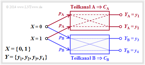
| − | <br> | + | <br>The diagram illustrates this definition for $L = 2$, where the subchannels are labelled $\rm A$ and $\rm B$ . |
| − | * | + | *The differently drawn transitions (dashed or dotted) show that the two partial channels can be different, so that $C_{\rm A} ≠ C_{\rm B}$ will generally apply. |
| − | * | + | *For the capacity of the total channel one thus obtains in general: |
:$$C = p_{\rm A} \cdot C_{\rm A} + p_{\rm B} \cdot C_{\rm B} \hspace{0.05cm}.$$ | :$$C = p_{\rm A} \cdot C_{\rm A} + p_{\rm B} \cdot C_{\rm B} \hspace{0.05cm}.$$ | ||
| − | * | + | *No statement is made here about the structure of the two partial channels. |
<br clear=all> | <br clear=all> | ||
| − | + | The following example will show that the ''Binary Erasure Channel'' $\rm (BEC)$ can also be described in principle by this diagram. However, the two output symbols $y_3$ and $y_4$ must then be combined into a single symbol. | |
[[File:P_ID2796__Inf_T_3_3_S6d.png|right|frame|$\rm (BEC)$ in zwei verschiedenen Darstellungen]] | [[File:P_ID2796__Inf_T_3_3_S6d.png|right|frame|$\rm (BEC)$ in zwei verschiedenen Darstellungen]] | ||
Revision as of 16:54, 6 April 2021
Contents
- 1 Information-theoretical model of digital signal transmission
- 2 Directional diagram for digital signal transmission
- 3 Calculation of the mutual information for the binary channel
- 4 Definition and meaning of channel capacity
- 5 Channel capacity of a binary channel
- 6 Properties of symmetrical channels
- 7 Einige Grundlagen der Kanalcodierung
- 8 Zusammenhang zwischen Blockfehlern und Bitfehlern
- 9 Rate, Kanalkapazität und Bitfehlerwahrscheinlichkeit
- 10 Aufgaben zum Kapitel
- 11 Quellenverzeichnis
Information-theoretical model of digital signal transmission
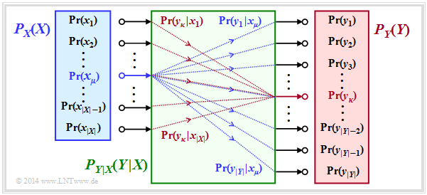
The entropies defined so far in general terms are now applied to digital signal transmission, whereby we assume a discrete memoryless channel (DMC) according to the graphic:
- The set of possible source symbols is characterised by the discrete random variable $X$ , where $|X|$ indicates the source symbol range:
- $$X = \{\hspace{0.05cm}x_1\hspace{0.05cm}, \hspace{0.15cm} x_2\hspace{0.05cm},\hspace{0.15cm} \text{...}\hspace{0.1cm} ,\hspace{0.15cm} x_{\mu}\hspace{0.05cm}, \hspace{0.15cm}\text{...}\hspace{0.1cm} , \hspace{0.15cm} x_{|X|}\hspace{0.05cm}\}\hspace{0.05cm}.$$
- Correspondingly, $Y$ characterises the set of sink symbols with the symbol range $|Y|$:
- $$Y = \{\hspace{0.05cm}y_1\hspace{0.05cm}, \hspace{0.15cm} y_2\hspace{0.05cm},\hspace{0.15cm} \text{...}\hspace{0.1cm} ,\hspace{0.15cm} y_{\kappa}\hspace{0.05cm}, \hspace{0.15cm}\text{...}\hspace{0.1cm} , \hspace{0.15cm} Y_{|Y|}\hspace{0.05cm}\}\hspace{0.05cm}.$$
- Usually $|Y| = |X|$is valid. Also possible is $|Y| > |X|$, for example with the Binary Erasure Channel (BEC) with $X = \{0,\ 1\}$, $Y = \{0,\ 1,\ \ \text{E}\}$ ⇒ $|X| = 2$, $|Y| = 3$.
- The sink symbol $\rm E$ indicates an erasure. The event $Y=\text{E}$ indicates that a decision for $0$ or for $1$ would be too uncertain.
- The symbol probabilities of the source and sink are accounted for in the graph by the probability functions $P_X(X)$ and $P_Y(Y)$ , where:
- $$P_X(x_{\mu}) = {\rm Pr}( X = x_{\mu})\hspace{0.05cm}, \hspace{0.3cm} P_Y(y_{\kappa}) = {\rm Pr}( Y = y_{\kappa})\hspace{0.05cm}.$$
- Let it hold: $P_X(X)$ and $P_Y(Y)$ contain no zeros ⇒ $\text{supp}(P_X) = P_X$ and $\text{supp}(P_Y) = P_Y$.
This precondition facilitates the model description without loss of generality. - All transition probabilities of the discrete memoryless channel $\rm (DMC)$ are captured by the conditional probability function $P_{Y|X}(Y|X)$ .
Mit $x_μ ∈ X$ and $y_κ ∈ Y$ , the following definition applies to this:
- $$P_{Y\hspace{0.01cm}|\hspace{0.01cm}X}(y_{\kappa}\hspace{0.01cm} |\hspace{0.01cm} x_{\mu}) = {\rm Pr}(Y\hspace{-0.1cm} = y_{\kappa}\hspace{0.03cm} | \hspace{0.03cm}X \hspace{-0.1cm}= x_{\mu})\hspace{0.05cm}.$$
The green block in the graph marks $P_{Y|X}(⋅)$ with $|X|$ inputs and $|Y|$ outputs. Blue connections mark transition probabilities $\text{Pr}(y_i | x_μ)$ starting from $x_μ$ with $1 ≤ i ≤ |Y|$, while all red connections end at $y_κ$: $\text{Pr}(y_κ | x_i)$ with $1 ≤ i ≤ |X|$.
Before we give the entropies for the individual probability functions, viz.
- $$P_X(X) ⇒ H(X),\hspace{0.5cm} P_Y(Y) ⇒ H(Y), \hspace{0.5cm} P_{XY}(X) ⇒ H(XY), \hspace{0.5cm} P_{Y|X}(Y|X) ⇒ H(Y|X),\hspace{0.5cm} P_{X|Y}(X|Y) ⇒ H(X|Y),$$
the above statements are to be illustrated by an example.
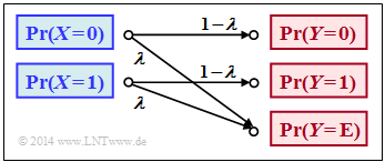
$\text{Example 1}$: In the book „Channel Coding” we also deal with the Binary Erasure Channel $\rm (BEC)$, which is sketched in a somewhat modified form on the right. The following prerequisites apply:
- Let the input alphabet be binary ⇒ $X = \{0,\ 1 \}$ ⇒ $\vert X\vert = 2$while three values are possible at the output ⇒ $Y = \{0,\ 1,\ \text{E} \}$ ⇒ $\vert Y\vert = 3$.
- The symbol $\text{E}$ indicates the case that the receiver cannot decide for one of the binary symbols $0$ or $1$ due to too much channel interference. „E” stands for erasure.
- With the $\rm BEC$ according to the above sketch, both a transmitted $0$ and a $1$ are erased with probability $λ$ while the probability of a correct transmission is $1 – λ$ in each case.
- In contrast, transmission errors are excluded by the BEC model
⇒ the conditional probabilities $\text{Pr}(Y = 1 \vert X = 0)$ and $\text{Pr}(Y = 0 \vert X = 1)$ are both zero.
At the transmitter, the zeros and ones would not necessarily be equally probable. Rather, we use the probability functions
- $$\begin{align*}P_X(X) & = \big ( {\rm Pr}( X = 0)\hspace{0.05cm},\hspace{0.2cm} {\rm Pr}( X = 1) \big )\hspace{0.05cm},\\ P_Y(Y) & = \big ( {\rm Pr}( Y = 0)\hspace{0.05cm},\hspace{0.2cm} {\rm Pr}( Y = 1)\hspace{0.05cm},\hspace{0.2cm} {\rm Pr}( Y = {\rm E}) \big )\hspace{0.05cm}.\end{align*}$$
From the above model we then get:
- $$\begin{align*}P_Y(0) & = {\rm Pr}( Y \hspace{-0.1cm} = 0) = P_X(0) \cdot ( 1 - \lambda)\hspace{0.05cm}, \\ P_Y(1) & = {\rm Pr}( Y \hspace{-0.1cm} = 1) = P_X(1) \cdot ( 1 - \lambda)\hspace{0.05cm}, \\ P_Y({\rm E}) & = {\rm Pr}( Y \hspace{-0.1cm} = {\rm E}) = P_X(0) \cdot \lambda \hspace{0.1cm}+\hspace{0.1cm} P_X(1) \cdot \lambda \hspace{0.05cm}.\end{align*}$$
If we now take $P_X(X)$ and $P_Y(Y)$ to be vectors, the result can be represented as follows:
- $$P_{\hspace{0.05cm}Y}(Y) = P_X(X) \cdot P_{\hspace{0.05cm}Y\hspace{-0.01cm}\vert \hspace{-0.01cm}X}(Y\hspace{-0.01cm} \vert \hspace{-0.01cm} X) \hspace{0.05cm},$$
where the transition probabilities $\text{Pr}(y_κ\vert x_μ)$ are accounted for by the following matrix:
- $$P_{\hspace{0.05cm}Y\hspace{-0.01cm} \vert \hspace{-0.01cm}X}(Y\hspace{-0.01cm} \vert \hspace{-0.01cm} X) = \begin{pmatrix} 1 - \lambda & 0 & \lambda\\ 0 & 1 - \lambda & \lambda \end{pmatrix}\hspace{0.05cm}.$$
Note:
- We have chosen this representation only to simplify the description.
- $P_X(X)$ and $P_Y(Y)$ are not vectors in the true sense and $P_{Y \vert X}(Y\vert X)$ is not a matrix either.
Directional diagram for digital signal transmission
All entropies defined in the last chapter also apply to digital signal transmission. However, it is expedient to choose the right-hand diagram instead of the diagram used so far, corresponding to the left-hand diagram, in which the direction from source $X$ to sink $Y$ is recognisable.
Let us now interpret the right graph starting from the general DMC channel model :
- The source entropy $H(X)$ denotes the average information content of the source symbol sequence. With the symbol range $|X|$ applies:
- $$H(X) = {\rm E} \left [ {\rm log}_2 \hspace{0.1cm} \frac{1}{P_X(X)}\right ] \hspace{0.1cm} = -{\rm E} \big [ {\rm log}_2 \hspace{0.1cm}{P_X(X)}\big ] \hspace{0.2cm} =\hspace{0.2cm} \sum_{\mu = 1}^{|X|} P_X(x_{\mu}) \cdot {\rm log}_2 \hspace{0.1cm} \frac{1}{P_X(x_{\mu})} \hspace{0.05cm}.$$
- The equivocation $H(X|Y)$ indicates the average information content that an observer who knows exactly about sink $Y$ gains by observing source $X$ :
- $$H(X|Y) = {\rm E} \left [ {\rm log}_2 \hspace{0.1cm} \frac{1}{P_{\hspace{0.05cm}X\hspace{-0.01cm}|\hspace{-0.01cm}Y}(X\hspace{-0.01cm} |\hspace{0.03cm} Y)}\right ] \hspace{0.2cm}=\hspace{0.2cm} \sum_{\mu = 1}^{|X|} \sum_{\kappa = 1}^{|Y|} P_{XY}(x_{\mu},\hspace{0.05cm}y_{\kappa}) \cdot {\rm log}_2 \hspace{0.1cm} \frac{1}{P_{\hspace{0.05cm}X\hspace{-0.01cm}|\hspace{0.03cm}Y} (\hspace{0.05cm}x_{\mu}\hspace{0.03cm} |\hspace{0.05cm} y_{\kappa})} \hspace{0.05cm}.$$
- The equivocation is the portion of the source entropy $H(X)$ that is lost due to channel interference (for digital channel: transmission errors) . The mutual information $I(X; Y)$ remains, which reaches the sink:
- $$I(X;Y) = {\rm E} \left [ {\rm log}_2 \hspace{0.1cm} \frac{P_{XY}(X, Y)}{P_X(X) \cdot P_Y(Y)}\right ] \hspace{0.2cm} = H(X) - H(X|Y) \hspace{0.05cm}.$$
- The irrelevance $H(Y|X)$ indicates the average information content that an observer who knows exactly about the source $X$ gains by observing the sink $Y$ :
- $$H(Y|X) = {\rm E} \left [ {\rm log}_2 \hspace{0.1cm} \frac{1}{P_{\hspace{0.05cm}Y\hspace{-0.01cm}|\hspace{-0.01cm}X}(Y\hspace{-0.01cm} |\hspace{0.03cm} X)}\right ] \hspace{0.2cm}=\hspace{0.2cm} \sum_{\mu = 1}^{|X|} \sum_{\kappa = 1}^{|Y|} P_{XY}(x_{\mu},\hspace{0.05cm}y_{\kappa}) \cdot {\rm log}_2 \hspace{0.1cm} \frac{1}{P_{\hspace{0.05cm}Y\hspace{-0.01cm}|\hspace{0.03cm}X} (\hspace{0.05cm}y_{\kappa}\hspace{0.03cm} |\hspace{0.05cm} x_{\mu})} \hspace{0.05cm}.$$
- The sink entropy $H(Y)$, the mean information content of the sink, is the sum of the useful mutual information $I(X; Y)$ and the irrelevance $H(Y|X)$, which comes exclusively from channel errors:
- $$H(Y) = {\rm E} \left [ {\rm log}_2 \hspace{0.1cm} \frac{1}{P_Y(Y)}\right ] \hspace{0.1cm} = -{\rm E} \big [ {\rm log}_2 \hspace{0.1cm}{P_Y(Y)}\big ] \hspace{0.2cm} =I(X;Y) + H(Y|X) \hspace{0.05cm}.$$
Calculation of the mutual information for the binary channel
These definitions will now be illustrated by an example. We deliberately avoid simplifying the calculations by exploiting symmetries.
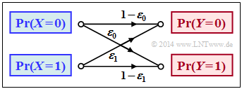
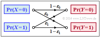
$\text{Example 2}$: We consider the general binary channel without memory according to the sketch. Let the falsification probabilities be:
- $$\begin{align*}\varepsilon_0 & = {\rm Pr}(Y\hspace{-0.1cm} = 1\hspace{0.05cm}\vert X \hspace{-0.1cm}= 0) = 0.01\hspace{0.05cm},\\ \varepsilon_1 & = {\rm Pr}(Y\hspace{-0.1cm} = 0\hspace{0.05cm} \vert X \hspace{-0.1cm}= 1) = 0.2\hspace{0.05cm}\end{align*}$$
- $$\Rightarrow \hspace{0.3cm} P_{\hspace{0.05cm}Y\hspace{-0.01cm} \vert \hspace{-0.01cm}X}(Y\hspace{-0.01cm} \vert \hspace{-0.01cm} X) = \begin{pmatrix} 1 - \varepsilon_0 & \varepsilon_0\\ \varepsilon_1 & 1 - \varepsilon_1 \end{pmatrix} = \begin{pmatrix} 0.99 & 0.01\\ 0.2 & 0.8 \end{pmatrix} \hspace{0.05cm}.$$
Furthermore, we assume source symbols that are not equally probable:
- $$P_X(X) = \big ( p_0, p_1 \big )= \big ( 0.1,\ 0.9 \big ) \hspace{0.05cm}.$$
With the binary entropy function $H_{\rm bin}(p)$ , we thus obtain for the source entropy:
- $$H(X) = H_{\rm bin} (0.1) = 0.4690 \,{\rm bit} \hspace{0.05cm}.$$
For the probability function of the sink as well as for the sink entropy we thus obtain:
- $$P_Y(Y) = \big [ {\rm Pr}( Y\hspace{-0.1cm} = 0)\hspace{0.05cm}, \ {\rm Pr}( Y \hspace{-0.1cm}= 1) \big ] = \big ( p_0\hspace{0.05cm},\ p_1 \big ) \cdot \begin{pmatrix} 1 - \varepsilon_0 & \varepsilon_0\\ \varepsilon_1 & 1 - \varepsilon_1 \end{pmatrix} $$
- $$\begin{align*}\Rightarrow \hspace{0.3cm} {\rm Pr}( Y \hspace{-0.1cm}= 0)& = p_0 \cdot (1 - \varepsilon_0) + p_1 \cdot \varepsilon_1 = 0.1 \cdot 0.99 + 0.9 \cdot 0.2 = 0.279\hspace{0.05cm},\\ {\rm Pr}( Y \hspace{-0.1cm}= 1) & = 1 - {\rm Pr}( Y \hspace{-0.1cm}= 0) = 0.721\end{align*}$$
- $$\Rightarrow \hspace{0.2cm} H(Y) = H_{\rm bin} (0.279) = 0.8541 \,{\rm bit} \hspace{0.05cm}. $$
The joint probabilities $p_{\mu \kappa} = \text{Pr}\big[(X = μ) ∩ (Y = κ)\big]$ between source and sink are:
- $$\begin{align*}p_{00} & = p_0 \cdot (1 - \varepsilon_0) = 0.099\hspace{0.05cm},\hspace{0.5cm}p_{01}= p_0 \cdot \varepsilon_0 = 0.001\hspace{0.05cm},\\ p_{10} & = p_1 \cdot (1 - \varepsilon_1) = 0.180\hspace{0.05cm},\hspace{0.5cm}p_{11}= p_1 \cdot \varepsilon_1 = 0.720\hspace{0.05cm}.\end{align*}$$
From this one obtains for
- the joint entropy:
- $$H(XY) = p_{00}\hspace{-0.05cm} \cdot \hspace{-0.05cm}{\rm log}_2 \hspace{0.05cm} \frac{1}{p_{00} \rm } + p_{01} \hspace{-0.05cm} \cdot \hspace{-0.05cm}{\rm log}_2 \hspace{0.05cm} \frac{1}{p_{01} \rm } + p_{10}\hspace{-0.05cm} \cdot \hspace{-0.05cm} {\rm log}_2 \hspace{0.05cm} \frac{1}{p_{10} \rm } + p_{11} \hspace{-0.05cm} \cdot \hspace{-0.05cm} {\rm log}_2\hspace{0.05cm} \frac{1}{p_{11}\rm } = 1.1268\,{\rm bit} \hspace{0.05cm},$$
- the mutual information:
- $$I(X;Y) = H(X) + H(Y) - H(XY) = 0.4690 + 0.8541 - 1.1268 = 0.1963\,{\rm bit} \hspace{0.05cm},$$
- the equivocation:
- $$H(X \vert Y) \hspace{-0.01cm} =\hspace{-0.01cm} H(X) \hspace{-0.01cm} -\hspace{-0.01cm} I(X;Y) \hspace{-0.01cm} $$
- $$\Rightarrow \hspace{0.3cm} H(X \vert Y) \hspace{-0.01cm} = \hspace{-0.01cm} 0.4690\hspace{-0.01cm} -\hspace{-0.01cm} 0.1963\hspace{-0.01cm} =\hspace{-0.01cm} 0.2727\,{\rm bit} \hspace{0.05cm},$$
- the irrelevance:
- $$H(Y \vert X) = H(Y) - I(X;Y) $$
- $$\Rightarrow \hspace{0.3cm} H(Y \vert X) = 0.8541 - 0.1963 = 0.6578\,{\rm bit} \hspace{0.05cm}.$$
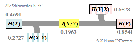
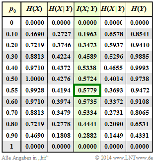
The results are summarised in the graph.
Notes:
- The equivocation and irrelevance could also have been calculated directly (but with extra effort) from the corresponding probability functions.
- For example, the irrelevance:
- $$H(Y|X) = \hspace{-0.2cm} \sum_{(x, y) \hspace{0.05cm}\in \hspace{0.05cm}XY} \hspace{-0.2cm} P_{XY}(x,\hspace{0.05cm}y) \cdot {\rm log}_2 \hspace{0.1cm} \frac{1}{P_{\hspace{0.05cm}Y\hspace{-0.01cm}|\hspace{0.03cm}X} (\hspace{0.05cm}y\hspace{0.03cm} |\hspace{0.05cm} x)}= p_{00} \cdot {\rm log}_2 \hspace{0.1cm} \frac{1}{1\hspace{-0.08cm} - \hspace{-0.08cm}\varepsilon_0} + p_{01} \cdot {\rm log}_2 \hspace{0.1cm} \frac{1}{\varepsilon_0} + p_{10} \cdot {\rm log}_2 \hspace{0.1cm} \frac{1}{1\hspace{-0.08cm} - \hspace{-0.08cm}\varepsilon_1} + p_{11} \cdot {\rm log}_2 \hspace{0.1cm} \frac{1}{\varepsilon_1} = 0.6578\,{\rm bit} \hspace{0.05cm}.$$
Definition and meaning of channel capacity
We further consider a discrete memoryless channel (DMC) with a finite number of source symbols ⇒ $|X|$ and also only finitely many sink symbols ⇒ $|Y|$, , as shown in the first section of this chapter.
- If one calculates the mutual information $I(X, Y)$ as last explained in $\text{example 2}$ ausgeführt, it also depends on the source statistic ⇒ $P_X(X)$ .
- Ergo: The mutual information $I(X, Y)$ is not a pure channel characteristic.
$\text{Definition:}$ The channel capacity introduced by Claude E. Shannon according to his standard work [Sha48][1] reads:
- $$C = \max_{P_X(X)} \hspace{0.15cm} I(X;Y) \hspace{0.05cm}.$$
Since according to this definition the best possible source statistics are always the basis, $C$ depends only on the channel properties ⇒ $P_{Y \vert X}(Y \vert X)$ ab, , but not on the source statistics ⇒ $P_X(X)$. Often the additional unit „bit/channel use” .
Shannon needed the channel description quantity $C$ to formulate the channel coding theorem – one of the highlights of the information theory he founded.
$\text{Shannon's channel coding theorem: }$
- For every transmission channel with channel capacity $C > 0$ , there exists (at least) one $(k, n)$–block code, whose (block) error probability approaches zero as long as the code rate $R = k/n$ is less than or equal to the channel capacity:
- $$R ≤ C.$$
- The prerequisite for this, however, is that the following applies to the block length of this code:
- $$n → ∞.$$
The proof of this theorem, which is beyond the scope of our learning tutorial, can be found for example in [CT06][2], [Kra13][3] und [Meck09][4].
As will be shown in task 3.13 , the reverse also is true. This proof can also be found in the literature references just mentioned.
$\text{Reverse of Shannon's channel coding theorem: }$
If the rate $R$ of the $(n$, $k)$–block code used is greater than the channel capacity $C$, then an arbitrarily small block error probability is not achievable.
In the chapter AWGN model for discrete-time band-limited signals it is explained in connection with the continuous-value AWGN channel model what phenomenally great significance Shannon's information-theoretical theorem has for the entire field of information technology, not only for those interested exclusively in theory, but also for practitioners.
Channel capacity of a binary channel
The mutual information of the general (asymmetrical) binary channel according to this sketch was calculated in $\text{example 2}$ . In this model, the input symbols $0$ and $1$ are distorted to different degrees:
- $$P_{\hspace{0.05cm}Y\hspace{-0.01cm}|\hspace{-0.01cm}X}(Y\hspace{-0.01cm} |\hspace{-0.01cm} X) = \begin{pmatrix} 1 - \varepsilon_0 & \varepsilon_0\\ \varepsilon_1 & 1 - \varepsilon_1 \end{pmatrix} \hspace{0.05cm}.$$
The mutual information can be represented with the probability function $P_X(X) = (p_0,\ p_1)$ as follows:
- $$I(X ;Y) = \sum_{\mu = 1}^{2} \hspace{0.1cm}\sum_{\kappa = 1}^{2} \hspace{0.2cm} {\rm Pr} (\hspace{0.05cm}y_{\kappa}\hspace{0.03cm} |\hspace{0.05cm} x_{\mu}) \cdot {\rm Pr} (\hspace{0.05cm}x_{\mu}\hspace{0.05cm})\cdot {\rm log}_2 \hspace{0.1cm} \frac{{\rm Pr} (\hspace{0.05cm}y_{\kappa}\hspace{0.03cm} |\hspace{0.05cm} x_{\mu})}{{\rm Pr} (\hspace{0.05cm}y_{\kappa})} $$
- $$\begin{align*}\Rightarrow \hspace{0.3cm} I(X ;Y) &= \hspace{-0.01cm} (1 \hspace{-0.08cm}- \hspace{-0.08cm}\varepsilon_0) \cdot p_0 \cdot {\rm log}_2 \hspace{0.1cm} \frac{1 \hspace{-0.08cm}- \hspace{-0.08cm}\varepsilon_0}{(1 \hspace{-0.08cm}- \hspace{-0.08cm}\varepsilon_0) \cdot p_0 + \varepsilon_1 \cdot p_1} + \varepsilon_0 \cdot p_0 \cdot {\rm log}_2 \hspace{0.1cm} \frac{\varepsilon_0}{(1 \hspace{-0.08cm}- \hspace{-0.08cm}\varepsilon_0) \cdot p_0 + \varepsilon_1 \cdot p_1} + \\ & + \hspace{-0.01cm} \varepsilon_1 \cdot p_1 \cdot {\rm log}_2 \hspace{0.1cm} \frac{\varepsilon_1}{\varepsilon_0 \cdot p_0 + (1 \hspace{-0.08cm}- \hspace{-0.08cm}\varepsilon_1) \cdot p_1} + (1 \hspace{-0.08cm}- \hspace{-0.08cm}\varepsilon_1) \cdot p_1 \cdot {\rm log}_2 \hspace{0.1cm} \frac{1 \hspace{-0.08cm}- \hspace{-0.08cm}\varepsilon_1}{\varepsilon_0 \cdot p_0 + (1 \hspace{-0.08cm}- \hspace{-0.08cm}\varepsilon_1) \cdot p_1} \hspace{0.05cm}.\end{align*}$$
$\text{Example 3}$: In the following we set $ε_0 = 0.01$ and $ε_1 = 0.2$.
Column 4 of the adjacent table shows (highlighted in green) the transinformation $I(X; Y)$ of this asymmetrical binary channel depending on the source symbol probability $p_0 = {\rm Pr}(X = 0)$ . One can see:
- The mutual information depends on the symbol probabilities $p_0$ und $p_1 = 1 - p_0$ ab.
- The maximum value of $I(X; Y)$ here results in $p_0 ≈ 0.55$ ⇒ $p_1 ≈ 0.45$.
- The result $p_0 > p_1$ follows from the relation $ε_0 < ε_1$ (the zero is less distorted).
- The capacity of this channel is $C = 0.5779 \ \rm bit/use$.
In the above equation, the Binary Symmetric Channel $\rm (BSC)$ with parameters $ε = ε_0 = ε_1$ is also included as a special case. Hints:
- In task 3.10 the mutual information of the BSC channel is calculated for the system parameters $ε = 0.1$ and $p_0 = 0.2$ .
- In task 3.10Z its channel capacity is given as follows:
- $$C_{\rm BSC} = 1 - H_{\rm bin} (\varepsilon) \hspace{0.05cm}.$$
Properties of symmetrical channels
The capacity calculation of the (general) discrete memoryless channel is often complex. It simplifies decisively if symmetries of the channel are exploited.
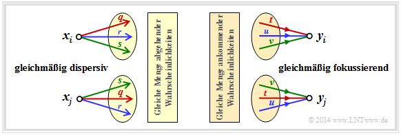
The diagram shows two examples:
- In the case of the uniformly dispersive channel all source symbols $x ∈ X$ result in exactly the same set of transition probabilities ⇒ $\{P_{Y\hspace{0.03cm}|\hspace{0.01cm}X}(y_κ\hspace{0.05cm}|\hspace{0.05cm}x)\}$ with $1 ≤ κ ≤ |Y|$. For the values $q$, $r$, $s$ , $q + r + s = 1$ must always apply here (left graph).
- In the case of the uniformly focusing channel , the same set of transition probabilities ⇒ $\{P_{Y\hspace{0.03cm}|\hspace{0.01cm}X}(y\hspace{0.05cm}|\hspace{0.05cm}x_μ)\}$ with $1 ≤ μ ≤ |X|$ results for all sink symbols $y ∈ Y$ . Here, $t + u + v = 1$ need not necessarily hold (right graph).
$\text{Definition:}$ If a discrete memoryless channel is both uniformly dispersive and uniformly focussing, it is a strongly symmetric channel vor. With an equally distributed source alphabet, this has the capacity
- $$C = {\rm log}_2 \hspace{0.1cm} \vert Y \vert + \sum_{y \hspace{0.05cm}\in\hspace{0.05cm} Y} \hspace{0.1cm} P_{\hspace{0.03cm}Y \vert \hspace{0.01cm} X}(y\hspace{0.05cm} \vert \hspace{0.05cm}x) \cdot {\rm log}_2 \hspace{0.1cm}P_{\hspace{0.01cm}Y \vert \hspace{0.01cm} X}(y\hspace{0.05cm}\vert\hspace{0.05cm} x) \hspace{0.05cm}.$$
Any $x ∈ X$ can be used for this equation.
This definition will now be clarified by an example.
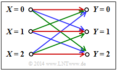
$\text{Example 4}$: In the channel under consideration, there are connections between $ \vert X \vert = 3$ inputs and all $ \vert Y \vert = 3$ outputs:
- A red connection stands for $P_{Y \hspace{0.03cm}\vert\hspace{0.01cm} X}(y_κ \hspace{0.05cm} \vert \hspace{0.05cm} x_μ) = 0.7$.
- A blue connection stands for $P_{Y \hspace{0.03cm}\vert\hspace{0.01cm} X}(y_κ \hspace{0.05cm}\vert \hspace{0.05cm} x_μ) = 0.2$.
- A green connection stands for $P_{Y \hspace{0.03cm}\vert\hspace{0.01cm} X}(y_κ \hspace{0.05cm}\vert\hspace{0.05cm} x_μ) = 0.1$.
According to the above equation, the following then applies to the channel capacity:
- $$C = {\rm log}_2 \hspace{0.1cm} (3) + 0.7 \cdot {\rm log}_2 \hspace{0.1cm} (0.7) + 0.2 \cdot {\rm log}_2 \hspace{0.1cm} (0.2) + 0.1 \cdot {\rm log}_2 \hspace{0.1cm} (0.1) = 0.4282 \,\,{\rm bit} \hspace{0.05cm}.$$
Notes:
- The addition of „the same set of transition probabilities” does not mean that $P_{Y \hspace{0.03cm}\vert\hspace{0.01cm} X}(y_κ \hspace{0.05cm}\vert\hspace{0.05cm} x_1) = P_{Y \hspace{0.03cm}\vert\hspace{0.01cm} X}(y_κ \hspace{0.05cm}\vert\hspace{0.05cm} x_2) = P_{Y \hspace{0.03cm}\vert\hspace{0.01cm} X}(y_κ \hspace{0.05cm}\vert\hspace{0.05cm} x_3)$ gelten muss.
- Rather, here a red, a blue and a green arrow leaves from each input and a red, a blue and a green arrow arrives at each output.
- The respective sequences permute: R – G – B, B – R – G, G – B – R.
An example of a strictly symmetrical channel is the Binary Symmetric Channel $\rm (BSC)$. In contrast, the Binary Erasure Channel $\rm (BEC)$ is not strictly symmetric,
- because, although it is uniformly dispersive,
- but it is not uniformly focussing.
The following definition is less restrictive than the previous one of a strictly symmetric channel.
$\text{Definition:}$ A 'symmetric channel exists,
- if it can be divided into several $($generally $L)$ strongly symmetrical sub-channels,
- by splitting the output alphabet $Y$ into $L$ subsetsn $Y_1$, ... , $Y_L$ .
Such a symmetrical channel has the following capacity:
- $$C = \sum_{l \hspace{0.05cm}=\hspace{0.05cm} 1}^{L} \hspace{0.1cm} p_{\hspace{0.03cm}l} \cdot C_{\hspace{0.03cm}l} \hspace{0.05cm}.$$
The following designations are used here:
- $p_{\hspace{0.03cm}l}$ indicates the probability that the dass der $l$–th partial channel is selected,
- $C_{\hspace{0.03cm}l}$ is the channel capacity of this $l$–th partial channel.
The diagram illustrates this definition for $L = 2$, where the subchannels are labelled $\rm A$ and $\rm B$ .
- The differently drawn transitions (dashed or dotted) show that the two partial channels can be different, so that $C_{\rm A} ≠ C_{\rm B}$ will generally apply.
- For the capacity of the total channel one thus obtains in general:
- $$C = p_{\rm A} \cdot C_{\rm A} + p_{\rm B} \cdot C_{\rm B} \hspace{0.05cm}.$$
- No statement is made here about the structure of the two partial channels.
The following example will show that the Binary Erasure Channel $\rm (BEC)$ can also be described in principle by this diagram. However, the two output symbols $y_3$ and $y_4$ must then be combined into a single symbol.
$\text{Beispiel 5}$: Die linke Grafik zeigt die übliche Darstellung des Binary Erasure Channels $\rm (BEC)$ mit Eingang $X = \{0,\ 1\}$ und Ausgang $Y = \{0,\ 1,\ \text{E} \}$.
Teilt man diesen entsprechend der rechten Grafik auf in
- einen idealen Kanal $(y = x)$ für
- $$y ∈ Y_{\rm A} = \{0, 1\} \ \ ⇒ \ \ C_{\rm A} = 1 \ \rm bit/use,$$
- einen Auslöschungskanal für
- $$y ∈ Y_{\rm B} = \{\rm E \} \ \ ⇒ \ \ C_{\rm B} = 0,$$
so ergibt sich mit den Teilkanalgewichtungen $p_{\rm A} = 1 – λ$ und $p_{\rm B} = λ$ für die Kanalkapazität:
- $$C_{\rm BEC} = p_{\rm A} \cdot C_{\rm A} = 1 - \lambda \hspace{0.05cm}.$$
Beide Kanäle sind streng symmetrisch. Für den (idealen) Kanal $\rm A$ gilt gleichermaßen
- für $X = 0$ und $X = 1$: $\text{Pr}(Y = 0 \hspace{0.05cm}\vert \hspace{0.05cm} X) = \text{Pr}(Y = 1 \hspace{0.05cm} \vert\hspace{0.05cm} X) = 1 - λ$ ⇒ gleichmäßig dispersiv,
- für $Y = 0$ und $Y = 1$: $\text{Pr}(Y \hspace{0.05cm} \vert \hspace{0.05cm} X= 0) = Pr(Y \hspace{0.05cm}\vert\hspace{0.05cm} X = 1) = 1 - λ$ ⇒ gleichmäßig fokussierend.
Entsprechendes gilt für den Auslöschungskanal $\rm B$.
In der Aufgabe 3.12 wird sich zeigen, dass die Kapazität des Kanalmodells Binary Symmetric Error & Erasure Channel $\rm (BSEC)$ in gleicher Weise berechnet werden kann. Man erhält:
- $$C_{\rm BSEC} = (1- \lambda) \cdot \left [ 1 - H_{\rm bin}(\frac{\varepsilon}{1- \lambda}) \right ]$$
- mit der Verfälschungswahrscheinlichkeit $ε$
- und der Auslöschungswahrscheinlichkeit $λ$.
Einige Grundlagen der Kanalcodierung
Um das Kanalcodierungstheorem richtig interpretieren zu können, sind einige Grundlagen der Kanalcodierung (englisch: Channel Coding) erforderlich. Dieses äußerst wichtige Gebiet der Nachrichtentechnik wird in unserem Lerntutorial $\rm LNTwww$ in einem eigenen Buch namens Channel Coding behandelt.
Die folgende Beschreibung bezieht sich auf das stark vereinfachte Modell für binäre Blockcodes:
- Die unendlich lange Quellensymbolfolge $\underline{u}$ (hier nicht dargestellt) wird in Blöcke zu jeweils $k$ Bit unterteilt. Wir bezeichnen den Informationsblock mit der laufenden Nummerierung $j$ mit $\underline{u}_j^{(k)}$.
- Jeder Informationsblock $\underline{u}_j^{(k)}$ wird durch den gelb hinterlegten Kanalcoder in ein Codewort $\underline{x}_j^{(n)}$ umgesetzt, wobei $n > k$ gelten soll. Das Verhältnis $R = k/n$ bezeichnet man als die Coderate.
- Der Discrete Memoryless Channel $\rm (DMC)$ wird durch Übergangswahrscheinlichkeiten $P_{Y\hspace{0.03cm}|\hspace{0.03cm}X}(⋅)$ berücksichtigt. Dieser grün hinterlegte Block bewirkt Fehler auf Bitebene. Es kann also gelten: $y_{j, \hspace{0.03cm}i} ≠ x_{j,\hspace{0.03cm} i}$.
- Damit können sich auch die aus $n$ Bit bestehenden Empfangsblöcke $\underline{y}_j^{(n)}$ von den Codeworten $\underline{x}_j^{(n)}$ unterscheiden . Ebenso gilt im allgemeinen für die Blöcke nach dem Deoder: $\underline{v}_j^{(k)} ≠ \underline{u}_j^{(k)}$.
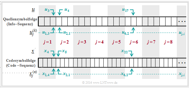
$\text{Beispiel 6}$: Die Grafik soll die hier verwendete Nomenklatur am Beispiel $k = 3$ und $n = 4$ verdeutlichen. Dargestellt sind die jeweils ersten acht Blöcke der Informationssequenz $\underline{u}$ und der Codesequenz $\underline{x}$.
Man erkennt folgende Zuordnung zwischen der geblockten und der ungeblockten Beschreibung:
- Bit 3 des 1. Info–Blocks ⇒ $u_{1,\hspace{0.08cm} 3}$ entspricht dem Symbol $u_3$ in ungeblockter Darstellung.
- Bit 1 des 2. Info–Blocks ⇒ $u_{2, \hspace{0.08cm}1}$ entspricht dem Symbol $u_4$ in ungeblockter Darstellung.
- Bit 2 des 6. Info–Blocks ⇒ $u_{6, \hspace{0.08cm}2}$ entspricht dem Symbol $u_{17}$ in ungeblockter Darstellung.
- Bit 4 des 1. Codewortes ⇒ $x_{1, \hspace{0.08cm}4}$ entspricht dem Symbol $x_4$ in ungeblockter Darstellung.
- Bit 1 des 2. Codewortes ⇒ $x_{2, \hspace{0.08cm}1}$ entspricht dem Symbol $x_5$ in ungeblockter Darstellung.
- Bit 2 des 6. Codewortes ⇒ $x_{6, \hspace{0.08cm}2}$ entspricht dem Symbol $x_{22}$ in ungeblockter Darstellung.
Zusammenhang zwischen Blockfehlern und Bitfehlern
Zur Interpretation des Kanalcodierungstheorems benötigen wir noch verschiedene Definitionen für „Fehlerwahrscheinlichkeiten”. Aus dem obigen Systemmodell lassen sich verschiedene Beschreibungsgrößen ableiten:
$\text{Definitionen:}$
- Die $\rm {Kanalfehlerwahrscheinlichkeit}$ ergibt sich beim vorliegenden Kanalmodell zu
- $${\rm Pr(Kanalfehler)} = {\rm Pr} \left ({y}_{j,\hspace{0.05cm} i} \ne {x}_{j,\hspace{0.05cm} i} \right )\hspace{0.05cm}.$$
- Beispielsweise ist beim BSC–Modell $\text{Pr(Kanalfehler)} = ε$ für alle $j = 1, 2$, ... und $1 ≤ i ≤ n$.
- Die $\rm {Blockfehlerwahrscheinlichkeit}$ bezieht sich auf die zugeordneten Informationsblöcke am Codereingang ⇒ $\underline{u}_j^{(k)}$ und am Decoderausgang ⇒ $\underline{v}_j^{(k)}$,
jeweils in Blöcken zu $k$ Bit:
- $${\rm Pr(Blockfehler)} = {\rm Pr} \left (\underline{\upsilon}_j^{(k)} \ne \underline{u}_j^{(k)} \right )\hspace{0.05cm}.$$
- Die $\rm {Bitfehlerwahrscheinlichkeit}$ bezieht sich ebenfalls auf den Eingang und den Ausgang des betrachteten Codiersystems, allerdings auf Bitebene:
- $${\rm Pr(Bitfehler)} = {\rm Pr} \left ({\upsilon}_{j,\hspace{0.05cm} i} \ne {u}_{j,\hspace{0.05cm} i} \right )\hspace{0.05cm}.$$
- Hierbei ist vereinfachend vorausgesetzt, dass alle $k$ Bit $u_{j,\hspace{0.08cm}i}$ des Informationsblockes $j$ mit gleicher Wahrscheinlichkeit verfälscht werden $(1 ≤ i ≤ k)$. Andernfalls müsste über die $k$ Bit noch gemittelt werden.
Zwischen der Blockfehler– und der Bitfehlerwahrscheinlichkeit besteht allgemein der Zusammenhang:
- $$\frac{1}{k} \cdot {\rm Pr(Blockfehler)} \le {\rm Pr(Bitfehler)} \le {\rm Pr(Blockfehler)} \hspace{0.05cm}.$$
- Die untere Schranke ergibt sich, wenn bei allen fehlerhaften Blöcken alle Bit falsch sind.
- Gibt es in jedem fehlerhaften Block genau nur einen einzigen Bitfehler, dann ist die Bitfehlerwahrscheinlichkeit ⇒ ${\rm Pr(Bitfehler)}$ identisch mit der Blockfehlerwahrscheinlichkeit ⇒ ${\rm Pr(Blockfehler)}$.
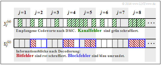
$\text{Beispiel 7:}$ Die Grafik zeigt oben die ersten acht Empfangsblöcke $\underline{y}_j^{(n)}$ mit jeweils $n = 4$ Bit. Kanalfehler sind grün schraffiert.
Unten ist die Ausgangsfolge $\underline{v}$ skizziert, unterteilt in Blöcke $\underline{v}_j^{(k)}$ mit jeweils $k = 3$ Bit:
- Bitfehler sind im unteren Diagramm rot schraffiert.
- Blockfehler erkennt man an der blauen Umrahmung.
Hierzu einige (aufgrund der kurzen Folge) nur sehr vage Angaben zu den Fehlerwahrscheinlichkeiten:
- Die Hälfte der Empfangsbits sind grün schraffiert. Daraus folgt:
- $${\rm Pr(Kanalfehler)} = 16/32 = 1/2.$$
- Die Bitfehlerwahrscheinlichkeit lautet mit der beispielhaften Codierung & Decodierung:
- $${\rm Pr(Bitfehler)} = 8/24 = 1/3.$$
- Dagegen würde bei uncodierter Übertragung gelten:
- $${\rm Pr(Bitfehler)} = {\rm Pr(Kanalfehler)} = 1/2.$$
- Die Hälfte der decodierten Blöcke sind blau umrandet. Daraus folgt:
- $${\rm Pr(Blockfehler)} = 4/8 = 1/2.$$
Mit ${\rm Pr(Blockfehler)}= 1/2$ und $k = 3$ liegt die Bitfehlerwahrscheinlichkeit in folgendem Bereich:
- $$1/6 \le {\rm Pr(Bitfehler)} \le 1/2 \hspace{0.05cm}.$$
- Die obere Schranke bezüglich Bitfehler ergibt sich, wenn in jedem der vier verfälschten Blöcke alle Bit falsch sind: ${\rm Pr(Bitfehler)} = 12/24 = 1/2.$
- Die untere Schranke gibt an, dass in jedem der vier verfälschten Blöcke jeweils nur ein Bit falsch ist: ${\rm Pr(Bitfehler)} = 4/24 = 1/6$.
Rate, Kanalkapazität und Bitfehlerwahrscheinlichkeit
Grundsätzlich gilt:
- Durch Kanalcodierung wird die Zuverlässigkeit (englisch: Reliability) der Datenübertragung von der Quelle zur Sinke erhöht.
- Vermindert man die Coderate $R = k/n$ und erhöht so die hinzugefügte Redundanz $(1 - R)$, so wird im allgemeinen die Datensicherheit verbessert und damit die Bitfehlerwahrscheinlichkeit herabgesetzt, die wir im Weiteren kurz mit $p_{\rm B}$ bezeichnen:
- $$p_{\rm B} = {\rm Pr(Bitfehler)} = {\rm Pr} \left ({\upsilon}_{j,\hspace{0.05cm} i} \ne {u}_{j,\hspace{0.05cm} i} \right )\hspace{0.05cm}.$$
Das folgende Theorem basiert auf dem Data Processing Theorem und Fano's Lemma. Die Herleitung kann in den Standardwerken zur Informationstheorie nachgelesen werden, zum Beispiel in [CT06][2]:
$\text{Umkehrung des Shannonschen Kanalcodierungstheorems:}$
Benutzt man zur Datenübertragung mit Rate $R$ einen Kanal mit zu kleiner Kapazität $C < R$, so kann die Bitfehlerwahrscheinlichkeit $p_{\rm B}$ auch bei bestmöglicher Kanalcodierung eine untere Schranke nicht unterschreiten:
- $$p_{\rm B} \ge H_{\rm bin}^{-1} \cdot \left ( 1 - {C}/{R}\right ) > 0\hspace{0.05cm}.$$
Hierbei bezeichnet $H_{\rm bin}(⋅)$ die binäre Entropiefunktion.
Da die Wahrscheinlichkeit der Blockfehler nie kleiner sein kann als die der Bitfehler, ist für $R > C$ auch die Blockfehlerwahrscheinlichkeit „Null” nicht möglich.
Aus den angegebenen Schranken für die Bitfehler,
- $$\frac {1}{k} \cdot {\rm Pr}({\rm Blockfehler}) \le {\rm Pr}({\rm Bitfehler}) \le {\rm Pr}({\rm Blockfehler})\hspace{0.05cm},$$
lässt sich auch ein Bereich für die Blockfehlerwahrscheinlichkeit angeben:
- $$ {\rm Pr}({\rm Bitfehler}) \le {\rm Pr}({\rm Blockfehler}) \le k \cdot {\rm Pr}({\rm Bitfehler})\hspace{0.05cm}.$$
$\text{Beispiel 8:}$ Bei einem Kanal mit Kapazität $C = 1/3$ (bit) ist eine fehlerfreie Datenübertragung $(p_{\rm B} = 0)$ mit der Coderate $R < 1/3$ prinzipiell möglich.
- Allerdings ist aus dem Kanalcodierungstheorem der spezielle $(k$, $n)$–Blockcode nicht bekannt, der dieses Wunschergebnis ermöglicht. Auch Shannon macht hierzu keine Aussagen.
- Bekannt ist nur, dass ein solcher bestmöglicher Code mit unendlich langen Blöcken arbeitet. Bei gegebener Coderate $R = k/n$ gilt somit sowohl $k → ∞$ als auch $n → ∞$.
- Deshalb ist die Aussage „Die Bitfehlerwahrscheinlichkeit ist Null” nicht identisch mit „Es treten keine Bitfehler auf”: Auch bei endlich vielen Bitfehlern und $k → ∞$ gilt nämlich $p_{\rm B} = 0$.
Mit der Coderate $R = 1 > C$ (uncodierte Übertragung) erhält man:
- $$p_{\rm B} \ge H_{\rm bin}^{-1} \cdot \left ( 1 - \frac{1/3}{1}\right ) = H_{\rm bin}^{-1}(2/3) \approx 0.174 > 0\hspace{0.05cm}.$$
Mit der Coderate $R = 1/2 > C$ ist die Bitfehlerwahrscheinlichkeit zwar kleiner, aber ebenfalls von Null verschieden:
- $$p_{\rm B} \ge H_{\rm bin}^{-1} \cdot \left ( 1 - \frac{1/3}{1/2}\right ) = H_{\rm bin}^{-1}(1/3) \approx 0.062 > 0\hspace{0.05cm}.$$
Aufgaben zum Kapitel
Aufgabe 3.10: Transinformation beim BSC
Aufgabe 3.10Z: BSC–Kanalkapazität
Aufgabe 3.11: Auslöschungskanal
Aufgabe 3.11Z: Extrem unsymmetrischer Kanal
Aufgabe 3.12: Streng symmetrische Kanäle
Aufgabe 3.13: Coderate und Zuverlässigkeit
Aufgabe 3.14: Kanalcodierungstheorem
Aufgabe 3.15: Data Processing Theorem
Quellenverzeichnis
- ↑ Shannon, C.E.: A Mathematical Theory of Communication. In: Bell Syst. Techn. J. 27 (1948), S. 379-423 und S. 623-656.
- ↑ 2.0 2.1 Cover, T.M.; Thomas, J.A.: Elements of Information Theory. West Sussex: John Wiley & Sons, 2nd Edition, 2006.
- ↑ Kramer, G.: Information Theory. Vorlesungsmanuskript, Lehrstuhl für Nachrichtentechnik, Technische Universität München, 2013.
- ↑ Mecking, M.: Information Theory. Vorlesungsmanuskript, Lehrstuhl für Nachrichtentechnik, Technische Universität München, 2009.
