Contents
- 1 OFDM using discrete Fourier transform (DFT)
- 2 Realization of the OFDM transmitter
- 3 Realization of the OFDM receiver
- 4 Intercarrier interference and intersymbol interference
- 5 Guard gap to reduce intersymbol interference
- 6 Cyclic Prefix
- 7 OFDM system with cyclic prefix
- 8 OFDM equalization in the frequency domain
- 9 OFDM equalization in matrix-vector notation
- 10 Advantages and disadvantages of OFDM
- 11 Exercises for the chapter
- 12 References
OFDM using discrete Fourier transform (DFT)
We now consider again the temporally non-overlapping transmitted signal frames
- $$s_k (t) = \sum\limits_{\mu = 0}^{N - 1} {a_{\mu ,\hspace{0.08cm}k} \cdot g_\mu (t - k \cdot T_{\rm{R}} )},$$
where $k$ indicates the frame number. At sampling times $k · T_{\rm R} + ν · T_{\rm A}$ with $0 ≤ ν < N$ and $T_{\rm A} = T/N$, these frames have the sampling values
- $$s_{\nu ,\hspace{0.08cm}k} = \sum\limits_{\mu = 0}^{N - 1} {a_{\mu ,\hspace{0.08cm}k} \cdot {\rm{e}}^{ {\kern 1pt} {\rm{j\hspace{0.03cm}\cdot \hspace{0.03cm}2\pi}} {\kern 1pt}\cdot \hspace{0.03cm}\nu \hspace{0.03cm}\cdot \hspace{0.03cm}{\mu}/{N}} }.$$
Here $T_{\rm R}$ denote the "frame duration" (German: "Rahmendauer" ⇒ subscript "R") and $T_{\rm A}$ the "sampling distance" (German: "Abtastabstand" ⇒ subscript "A").
- With the renaming $s_{ν,\hspace{0.08cm}k} = d_{ν,\hspace{0.08cm}k}$ and $a_{\mu,\hspace{0.08cm}k} = D_{\mu,\hspace{0.08cm}k}$ the equation corresponds exactly to the Inverse Discrete Fourier Transform $\rm (IDFT)$ in the $k$–th interval:
- $$d_{\nu ,\hspace{0.08cm}k} = \sum\limits_{\mu = 0}^{N - 1} {D_{\mu ,\hspace{0.08cm}k} \cdot w^{ - \nu \hspace{0.03cm}\cdot \hspace{0.03cm} \mu } } \quad {\rm{with}} \quad w = {\rm{e}}^{ - {\rm{j}} {\rm{\hspace{0.03cm}\cdot \hspace{0.03cm}2\pi}}/N}.$$
- Here, $d_{ν,\hspace{0.08cm}k}$ are the time samples and $D_{ν,\hspace{0.08cm}k}$ are the discrete spectral coefficients.
- The equation for the transition from the discrete time function to the discrete spectral function ⇒ Discrete Fourier Transform $\rm (DFT)$ is:
- $$D_{\mu ,\hspace{0.08cm}k} = \frac{1}{N}\cdot \sum\limits_{\nu = 0}^{N - 1} {d_{\nu ,\hspace{0.08cm}k} \cdot w^{\hspace{0.05cm}\nu \hspace{0.03cm}\cdot \hspace{0.03cm}\mu } }.$$
- Furthermore:
- The coefficients $d_{ν,\hspace{0.08cm}k}$ and $D_{μ,\hspace{0.08cm}k}$ are periodic with the grid number $N$. Moreover, they are in general complex-valued.
- In principle, DFT and IDFT have the same structure.
- They only differ by the sign in the exponent of the complex rotation factor $w$ and the normalization factor $1/N$ in the case of DFT.
$\text{Notes:}$
- The applet "Discrete Fourier Transform" clarifies the properties of DFT and IDFT.
- The possibility of an efficient realization of the multicarrier system results with the Fast Fourier Transform.
- For the use of FFT/IFFT, the number of interpolation points (or samples) in the time and frequency domain must be a power of two in each case.
- Under this condition, an implementation with the complexity $\mathcal{O}(N · {\rm log_2} \ N)$ is possible with the different known algorithms for the implementation of the FFT.
Realization of the OFDM transmitter
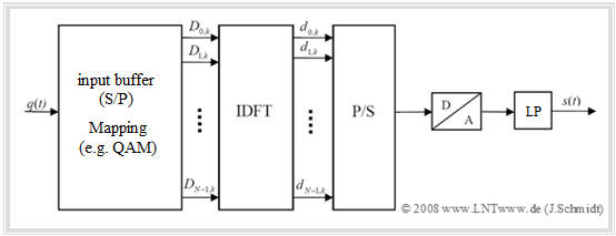
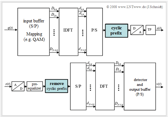
The diagram shows the block diagram for the realization of the OFDM transmitter using the "Inverse Discrete Fourier Transform" $\rm (IDFT)$.
- In the general model at the beginning of the last chapter, this replaces the very complex parallel demodulation of the $N$ orthogonal carriers.
- The implementation of the $\rm IDFT$ as $\rm IFFT$ (Inverse Fast Fourier Transform) results in a further reduction in effort.
One recognizes from this diagram:
- In the input buffer, the source signal $q(t)$ is implicitly serial/parallel $\rm (S/P)$ converted. After that, a signal space mapping to the $N$ spectral coefficients $D_{\mu,\hspace{0.08cm}k}$ is performed. The index $k$ again denotes the time frame.
- In $\rm 4–QAM$ mapping, each two source symbols together yield a complex coefficient $D_{\mu,\hspace{0.08cm}k}$, which can take four different values.
- The spectral coefficients $D_{\mu,\hspace{0.08cm}k}$ generated in this way are then fed to the $\rm IDFT$ block, which generates the time domain values $d_{ν,\hspace{0.08cm}k}$ from them. These are again parallel/serial $\rm (P/S)$ converted.
After the subsequent $\rm (D/A)$ conversion and low-pass filtering the $\rm OFDM$ transmitted signal $s(t)$ is finally obtained in the equivalent low-pass range.
Realization of the OFDM receiver
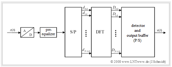
The diagram shows the block diagram for the realization of the OFDM receiver using the "Discrete Fourier Transform" $\rm (DFT)$.
This replaces in the general model (see last chapter) the very complex parallel demodulation of the $N$ orthogonal carriers.
The realization of the $\rm DFT$ as $\rm FFT$ ("Fast Fourier Transform") results in a further reduction of effort. The essential steps are:
- The input signal $r(t)$ of the receiver is first digitalized $(\rm A/D$ conversion$)$. This is followed by a pre-equalization in the time domain (optional), e.g. with Decision Feedback Equalization $($ $\rm DFE)$ or the Viterbi algorithm.
- It should be noted, that the decisive equalization happens in the frequency domain. This is explained in section OFDM equalization in the frequency domain at the end of the chapter and is not included in the diagram above.
- After serial/parallel $\rm (S/P)$ conversion, the discrete time values $d_{ν,\hspace{0.08cm}k}$ are fed to the DFT block. The generated spectral samples $D_{\mu,\hspace{0.08cm}k}$ are decoded by the QAM detector and implicitly parallel/serial converted in the output buffer, resulting in the sink signal $v(t)$.
- Note, that the receiver-side coefficients $d_{ν,\hspace{0.08cm}k}$ and $D_{\mu,\hspace{0.08cm}k}$ may well differ from the corresponding quantities of the OFDM transmitter due to channel distortion and noise, which is not reflected in the chosen nomenclature.
- Only in the case of error-free detection, the coefficients $\hat{a}_{\mu,\hspace{0.08cm}k}$ of the sink signal $v(t)$ are identical to the coefficients $a_{\mu,\hspace{0.08cm}k}$ of the source signal $q(t)$. In general, they differ, which is captured by the symbol error rate.
Intercarrier interference and intersymbol interference
$\text{Definitions:}$ Orthogonality of OFDM carriers is lost during transmission over a frequency-selective channel.
- The resulting interference between the individual carriers is called "intercarrier interference" $\rm (ICI)$.
- However, transmission over a multipath channel ultimately also causes superimposition of successive symbols and thus "intersymbol interference".
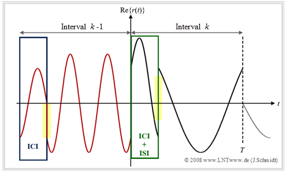
$\text{Example 1:}$ The diagram shows the real part of a received OFDM (equivalent low-pass) signal after transmission via a noise-free multipath channel with parameters:
- for the path "0": Attenuation $h_0 = 0.5$; delay $τ_0 = 0$,
- for the path "1": Attenuation $h_1 = 0.5$; delay $τ_1 = T/4$.
- The carrier of frequency $1 · f_0$ of the interval $k$ assigned with the coefficient "$+1$" is drawn in black.
- The carrier weighted with "$-1$" with frequency $3 · f_0$ in the previous interval $(k-\hspace{-0.08cm}1)$ is shown in red.
- Other intervals and carriers are not considered.
One can see from this diagram:
- Transient events at the symbol beginning lead to "intercarrier interference" $\rm (ICI)$ in the spectrum.
- In the time domain, $\rm ICI$ can be recognized by the jumps that occur (marked yellow in the diagram).
- As a result, orthogonality is lost with respect to the frequency grid points.
- Further one recognizes "intersymbol interference" $\rm (ISI)$ in the green framed time interval $0 ≤ t < τ_1$:
The red predecessor symbol $k-\hspace{-0.08cm}1$ $($frequency $3 · f_0)$ interferes with the black symbol $k$ $($frequency $1 · f_0)$.
Guard gap to reduce intersymbol interference
A first possible solution for the second problem $\rm (ISI)$ is the introduction of a guard gap of length $T_{\rm G}$:
- Here, the signal between two symbols is set to zero for the duration of the protection time $T_{\rm G}$.
- As a result, possible pulse trailers of symbol $k-\hspace{-0.08cm}1$ no longer extend into the following symbol $(k)$, provided that the guard gap is selected "wider" than the maximum channel delay.
- The new frame duration $T_{\rm R}$ – i.e. the distance between successive transmitted symbols – is thus given by
- $$T_{\rm R} = T + T_{\rm G}.$$
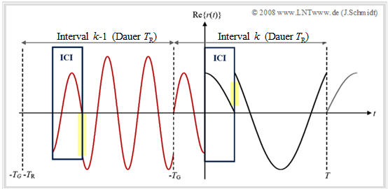
$\text{Example 2:}$ This diagram again shows the real part of the received OFDM signal, but now with "guard gap". The assumptions of $\text{Example 1}$ have been kept.
The diagram shows:
- In addition, $T_{\rm G} = T/4$ is set, which corresponds to the limiting case $T_{\rm G} = τ_{\rm max}$ for the present channel.
- By using a guard gap of corresponding width, intersymbol interference $\rm (ISI)$ can be avoided ⇒ in interval $k$ only one frequency occurs.
- But: Intercarrier interference $\rm (ICI)$ cannot be prevented by this, because the symbols still have a transient phase and thus jumps.
The "guard gap" approach will not be considered further. Rather, a better alternative is presented in the next section.
Cyclic Prefix
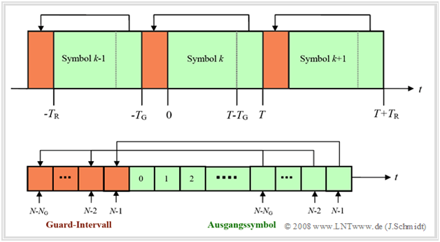
A better solution for the described problem is the introduction of a cyclic extension of the transmitted symbols in the so-called "guard interval" of length $T_{\rm G}$.
- For this, the end of a symbol in the time interval $T \ – \ T_{\rm G} ≤ t < T$ is prefixed again to the actual symbol.
- This procedure thus generates a cyclic prefix.
- As with the "guard gap", the interval duration increases from symbol duration $T$ to the new frame duration $T_{\rm R} = T + T_{\rm G}$.
- The new number of samples of the extended discrete-time signal in the $k$–th interval is then:
- $$N_{\rm{total}} = N + N_{\rm{G}} = N \cdot (1 + T_{\rm{G}} /T) .$$
- The number of carriers and the number of useful IDFT values is still $N$. Here, the expansion is only achieved by repeating the end of the symbol $N\hspace{-0.03cm}-\hspace{-0.08cm}N_0$, ... , $N\hspace{-0.08cm}-\hspace{-0.08cm}1$ in the guard interval (highlighted in red).
- The use of the "cyclic prefix" seems to be particularly useful if the $\rm ISI$ are mainly caused by tracking. This applies in particular to the copper twisted pairs used in DSL systems.
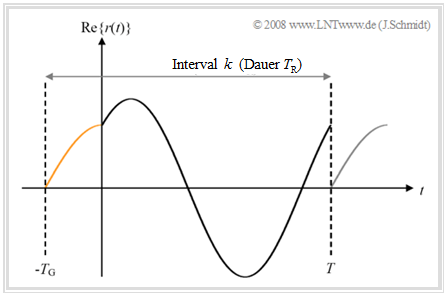
$\text{Example 3:}$ The diagram shows the operation of the guard interval in the continuous-time case. The parameters from the consideration of the guard gap in $\text{Example 1}$ still apply, although only one symbol $($with frequency $f_0)$ is now considered.
Further system parameters are again $T_{\rm G} = T/4$ and for path "0" or path "1":
- Attenuation $h_0 = 0.5$; delay $τ_0 = 0$,
- Attenuation $h_1 = 0.5$; delay $τ_1 = T/4$.
In the frame $k$ of duration $T_{\rm R}$, there is now no interference at all:
- Since the preceding symbols completely fade away during the guard interval, there is no "intersymbol interference" $\rm (ISI)$.
- Since the respective transients do not extend into the useful symbols, no "intercarrier interference" $\rm (ICI)$ occurs either.
$\text{Conclusion:}$
- By using a cyclic prefix alone, both "intercarrier interference" $\rm (ICI)$ and "intersymbol interference" $\rm (ISI)$ can be completely avoided.
- This requires that the length of the guard interval $(T_{\rm G})$ is at least equal to the maximum duration $τ_{\rm max}$ of the channel impulse response: $T_{\rm G} \ge τ_{\rm max}$.
- In the example considered, $T_{\rm G} = τ_{\rm max} = \tau_1$ .
- The quantity $τ_{\rm max}$ generally limits the ISI– and ICI–free section within the guard interval to the range $ \ –T_{\rm G} + τ_{\rm max} ≤ t < T$.
OFDM system with cyclic prefix
The "Cyclic prefix" block must therefore be added to the transmitter structure already shown at the beginning. At the receiver this prefix must be removed again.
- The definition of a suitable guard interval is an important design criterion for OFDM-based transmission systems. A possible approach to this is presented as an example in the section OFDM for 4G Networks.
- However, the use of a cyclic prefix degrades bandwidth efficiency. The degradation increases with increasing duration $T_{\rm G}$ of the guard interval - hereafter abbreviated as "GI".
- Under the simplifying assumption of a transmit spectrum $S(f)$ hard limited to $1/T$, the bandwidth efficiency – see [Kam04][1]:
- $$\beta = \frac{ {\rm symbol rate} }{ {\rm bandwidth} } = \frac{1/(T + T_{\rm G})}{1/T} = \frac{1}{{1 + T_{\rm{G}} /T}}.$$
- However, in a system using the so-called matched-filter approach, increasing the frame duration from $T$ to $T_{\rm G} + T$ leads to a decrease in the signal-to-noise ratio if the impulse responses $g_{\rm S}(t)$ and $g_{\rm E}(t)$ of the transmitted and reception filters are matched to the symbol duration $T$.
- The resulting Signal–to–Noise–Ratio $\rm (SNR)$ $\text{(in dB)}$ of the overall system can be calculated as follows, taking into account the guard interval:
- $${\rm{SNR}}_{\hspace{0.08cm}{\rm{ {\rm{with} }\hspace{0.08cm} GI} } } = {\rm{SNR}}_{\hspace{0.08cm}{\rm{{\rm{without}}\hspace{0.08cm} GI}}} + 10 \cdot \lg (\beta ), \quad {\rm{where}}$$
- $$\beta = \frac{{\left[ {\int\limits_0^T {g_{\rm{S}} (\tau ) \cdot g_{\rm{E}} ( - \tau )d\tau } } \right]^2 }}{{\int\limits_{ - T_{\rm{G}} }^T {g_{\rm{S}}^2 (\tau )} \,d\tau \cdot \int\limits_{\rm{0}}^T {g_{\rm{E}}^2 (\tau )} \,d\tau }} = \frac{ {T^2 } } { {(T + T_{\rm{G} } ) \cdot T} } = \frac{1}{ {1 + T_{\rm{G} } /T} }.$$
$\text{Example 4:}$ We assume a guard interval of length $T_{\rm G} = T/3$.
- Then the bandwidth efficiency is given by:
- $$\beta = \frac{1}{ {1 + 1/3} } = 3/4.$$
- The share of the cyclic prefix in the frame duration $T_{\rm R}$ is $25\%$ and the (logarithmic) SNR loss is then $10 · \lg \ (4/3) ≈ 1.25 \ \rm dB$.
The Applet OFDM Spectrum and Signals illustrates the operation of a cyclic prefix in the continuous-time case with respect to intercarrier interference $\rm (ICI)$.
OFDM equalization in the frequency domain
We continue to consider the OFDM system in the noise-free case and assume a time-invariant channel impulse response whose length is smaller than the duration $T_{\rm G}$ of the cyclic prefix added at the transmit end.
- The observation is made in the $k$–th interval, and indexing is omitted.
- The discrete-time channel impulse response can be written as $h_ν = h(ν · T_{\rm A})$ with the abbreviation $T_{\rm A} = T/N$.
- The discrete-time reception signal is thus obtained by linear convolution to:
- $$r_\nu = s_\nu * h_\nu = d_\nu * h_\nu.$$
This takes into account that the time samples $s_ν$ of the transmitted signal coincide with the IDFT coefficients $d_ν$.
$\text{To be noted:}$ In general, for the conventional linear convolution:
- $${\rm{DFT} } \{ d_\nu * h_\nu \} \ne {\rm{DFT} } \{d_\nu \} \cdot {\rm{DFT} } \{ h_\nu \}.$$
- Nevertheless, in order to specify the discrete received spectrum by the discrete Fourier transform $\rm (DFT)$, one needs the cyclic convolution (the terms circular convolution and periodic convolution are also used synonymously for this purpose):
- $$r_\nu = d_\nu * _{\rm (circ)} h_\nu \quad \circ\hspace{0.01cm}\!\!\!-\!\!\!-\!\!\!-\!\!\bullet \quad R_\mu = {\rm{DFT} } \{ d_\nu * _{\rm (circ)} h_\nu \}.$$
- Using the convolution theorem for linear time-invariant systems, one can then also write the spectrum as a product of two discrete Fourier transforms:
- $$R_\mu = {\rm{DFT} }\{ d_\nu \} \cdot {\rm{DFT} }\{ h_\nu \} = D_\mu \cdot H_\mu.$$
- To compensate for the influence of the channel on the reception sequence, it is convenient to multiply the spectrum by the inverse transfer function $1/H_{\mu}$.
- This "zero forcing" approach leads to the ideal signal reconstruction in the noise-free case. The equalization can be done point by point:
- $$\hat {D}_\mu = \frac{1}{ {H_\mu } } \cdot R_\mu.$$
$\text{Conclusion:}$
- In the OFDM system, channel equalization can be realized with a single multiplication per subcarrier if the channel frequency response is known.
- In contrast, a classic single-carrier system would require equalization of the entire frequency range used.
OFDM equalization in matrix-vector notation
In the following, a renewed but more in-depth consideration of OFDM equalization will be given, where we use matrix-vector notation. The consideration still refers to the $k$–th interval, without any special note:
- The vector of a channel with $L$ echoes is $\mathbf h = (h_0$, ... , $h_L)$. The transmission matrix with $N$ rows and $N + L$ columns is:
- $${\rm\bf{H}} = \left( {\begin{array}{*{20}c} {h_0 } & {h_1 } & \cdots & {h_L } & {} & {} & {} \\ {} & {h_0 } & {h_1 } & \cdots & {h_L } & {} & {} \\ {} & {} & \ddots & \ddots & {} & \ddots & {} \\ {} & {} & {} & {h_0 } & {h_1 } & \cdots & {h_L } \\ \end{array}} \right).$$
- Here, $N$ indicates the number of carriers and hence the number of time samples of the IDFT. With the transmit vector ${\bf d} = (d_0$, ... , $d_{N–1})$ the receive vector is:
- $$\bf r = d · H.$$
- Considering the cyclic prefix, the extended transmit vector is obtained:
- $${\rm\bf{d}}_{{\rm{ext}}} = (d_{N - N_G } , \ \ldots \ ,d_{N - 1} ,d_0 , \ \ldots \ ,d_{N - 1} ).$$
- Now one could extend the above transmission matrix $\bf H$ likewise accordingly on $(N + N_{\rm G})$ rows and $(N + L + N_{\rm G})$ columns as well as remove the prefix at the receiver again, which is not to be pursued here further.
Alternatively, one can use the cyclic matrix $\rm \bf H_C$ with $N$ rows and $N$ columns as well as the Fourier transform $\rm \bf F$ in matrix–vector notation:
- $${\rm\bf{H}}_{\rm{C}} = \left( {\begin{array}{*{20}c} {h_0 } & {h_1 } & \cdots & \cdots & {h_L } & {} & {} & {} \\ {} & {h_0 } & {h_1 } & \cdots & \cdots & {h_L } & {} & {} \\ {} & {} & \ddots & \ddots & {} & {} & \ddots & {} \\ {} & {} & {} & {h_0 } & {h_1 } & \cdots & \cdots & {h_L } \\ \hline {h_L } & {} & {} & {} & {h_0 } & {h_1 } & \cdots & {h_{L - 1} } \\ \vdots & \ddots & {} & {} & {} & \ddots & {} & \vdots \\ \vdots & {} & \ddots & {} & {} & {} & \ddots & \vdots \\ {h_1 } & \cdots & \cdots & {h_L } & {} & {} & {} & {h_0 } \\ \end{array}} \right), \hspace{1cm} {\rm\bf{F}} = \left( {\begin{array}{*{20}c} 1 & 1 & \cdots & 1 \\ 1 & {} & {} & {} \\ \vdots & {} & {{\rm{e}}^{ - {\rm{j \hspace{0.05cm}\cdot \hspace{0.03cm} 2\pi }}{\kern 1pt} \cdot \hspace{0.02cm}\nu {\kern 1pt} \cdot\mu /N} } & {} \\ 1 & {} & {} & {} \\ \end{array}} \right) .$$
- The Discrete Fourier Transform $\rm (DFT)$ can be represented by $1/N · \bf F$ and its inverse $\rm (IDFT)$ by $\rm \bf F^{\star}$ such that for the transmit vector: $\rm {\bf d} = {\bf D} · {\bf F}^{\star}$.
- The $N$ spectral coefficients are described by the vector ${\bf D} = 1/N · {\bf d} · {\bf F}$ and the reception vector is ${\bf r} = {\bf d} · {\bf H}_{\rm C} = {\bf D} · {\bf F}^{\star} · {\bf H}_{\rm C}$.
- The (discrete) Fourier transform $\rm \bf R$ of the reception vector $\rm \bf r$ can then be written in the following way:
- $${\rm\bf{R}} = \frac{1}{N} \cdot {\rm\bf{r}} \cdot {\rm\bf{F}} = {\rm\bf{D}} \cdot \left( {\begin{array}{*{20}c} {H_0 } & {} & {} & {} \\ {} & {H_1 } & {} & {} \\ {} & {} & \ddots & {} \\ {} & {} & {} & {H_{N - 1} } \\ \end{array}} \right),\hspace{0.25cm} {\rm with}\hspace{0.25cm} H_\mu = \sum\limits_{l = 0}^L {h_l \cdot {\rm{e}}^{ - {\rm{j \hspace{0.05cm}\cdot \hspace{0.03cm} 2\pi }}\hspace{0.05cm}\cdot \hspace{0.03cm} l \hspace{0.05cm}\cdot \hspace{0.03cm}\mu /N} }.$$
$\text{Conclusion:}$
- The reception symbol on the $\mu$–th carrier is:
- $$R_{\mu} = D_{\mu} · H_{\mu}.$$
- This can thus be equalized using the Zero Forcing approach:
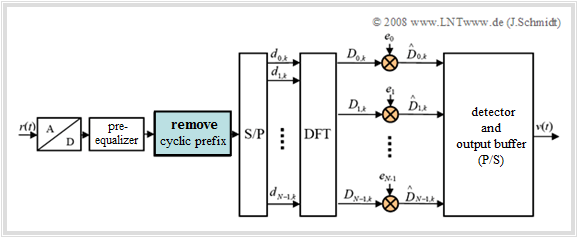
- $$\hat {D}_\mu = \frac{1}{ {H_\mu } } \cdot R_\mu = e_\mu \cdot R_\mu .$$
- Equalization with $e_{\mu} = 1/H_{\mu}, \ (\mu = 0,$ ... , $N–1)$ leads to the final block diagram of the OFDM receiver.
- The complete block diagram is shown on the right.
$\text{Example 5:}$ We assume a system with $N = 4$ carriers and a channel with $L = 2$ echoes, so that for the transmit vector ${\bf d} = (d_0, d_1, d_2, d_3)$ and for the channel impulse response ${\bf h} = (h_0, h_1, h_2)$.
(1) To represent the cyclic prefix, we use the cyclic transmission matrix ${\rm\bf{H} }_{\rm{C} }$, instead of the extended transmission vector with the corresponding transmission matrix, resulting in the reception vector ${\rm \bf r}= {\rm \bf d} \cdot {\rm \bf H}_{\rm{C} }$:
- $${\rm\bf{H} }_{\rm{C} } = \left( {\begin{array}{*{20}c} {h_0 } & {h_1 } & {h_2 } & { } \\ {} & {h_0 } & {h_1 } & {h_2 } \\ \hline {h_2 } & {} & {h_0 } & {h_1 } \\ {h_1 } & {h_2 } & {} & {h_0 } \\ \end{array} } \right), \hspace{1cm} {\rm\bf{r} } = \left( {r_0 ,r_1 ,r_2 ,r_3 } \right) = \left( {d_0 ,d_1 ,d_2 ,d_3 } \right) \cdot \left( {\begin{array}{*{20}c} {h_0 } & {h_1 } & {h_2 } & {} \\ {} & {h_0 } & {h_1 } & {h_2 } \\ \hline {h_2 } & {} & {h_0 } & {h_1 } \\ {h_1 } & {h_2 } & {} & {h_0 } \\ \end{array} } \right) $$
- $$\Rightarrow \hspace{0.3cm} r_0 = d_0 \cdot h_0 + d_2 \cdot h_2 + d_3 \cdot h_1, \hspace{0.5cm} r_1 = d_0 \cdot h_1 + d_1 \cdot h_0 + d_3 \cdot h_2,$$
- $$\Rightarrow \hspace{0.3cm} r_2 = d_0 \cdot h_2 + d_1 \cdot h_1 + d_2 \cdot h_0, \hspace{0.5cm} r_3 = d_1 \cdot h_2 + d_2 \cdot h_1 + d_3 \cdot h_0.$$
(2) The (discrete) Fourier transform of the receive vector is calculated to be
- $${\rm\bf{R} } = \frac{1}{N} \cdot {\rm\bf{r} } \cdot {\rm\bf{F} } = {\rm\bf{D} } \cdot \left( {\begin{array}{*{20}c} {H_0 } & {} & {} & {} \\ {} & {H_1 } & {} & {} \\ {} & {} & {H_2 } & {} \\ {} & {} & {} & {H_3 } \\ \end{array} } \right) ,\hspace{0.25cm} {\rm mit}\hspace{0.25cm} H_\mu = \sum\limits_{l = 0}^2 {h_l \cdot {\rm{e} }^{ - {\rm{j \hspace{0.05cm}\cdot \hspace{0.03cm} 2\pi } }\hspace{0.05cm}\cdot \hspace{0.03cm}l \hspace{0.05cm}\cdot \hspace{0.03cm} \mu /4} } .$$
(3) For the numerical calculation, we assume a known BPSK-encoded transmit sequence $\rm \bf D$ (in the frequency domain) and the following channel impulse response $\bf h$:
- $${\rm\bf{D} } = \frac{1}{N} \cdot {\rm\bf{d} } \cdot {\rm\bf{F} } = \left( D_0, D_1,D_2,D_3\right) = \left( +1,\ -1,\ +1,\ -1\right),$$
- $$ {\rm\bf{h} }= \left( h_0, h_1,h_2\right) = \left( 0.5,\ 0.3,\ 0.2\right).$$
(4) First, we determine the elements $H_{\mu}$ of the diagonal matrix:
- $$\begin{array}{l} H_0 = \sum\limits_{l = 0}^2 {h_l \cdot {\rm{e} }^0 = 0.5 + 0.3 + 0.2 = 1,} \\ H_1 = \sum\limits_{l = 0}^2 {h_l \cdot {\rm{e} }^{ - {\rm{j\hspace{0.05cm}\cdot \hspace{0.03cm} 2\pi } }\hspace{0.05cm}\cdot \hspace{0.03cm} l \hspace{0.05cm}\cdot \hspace{0.03cm} {1}/{4} } } = 0.5 \cdot {\rm{e} }^0 + 0.3 \cdot {\rm{e} }^{ - {\rm{j\hspace{0.05cm}\cdot \hspace{0.03cm}\pi } } /2 } + 0.2 \cdot {\rm{e} }^{ - {\rm{j\hspace{0.05cm}\cdot \hspace{0.03cm}\pi } } } = 0.3 - {\rm{j} } \cdot 0.3, \\ H_2 = \sum\limits_{l = 0}^2 {h_l \cdot {\rm{e} }^{ - {\rm{j\hspace{0.05cm}\cdot \hspace{0.03cm} 2\pi } }\hspace{0.05cm}\cdot \hspace{0.03cm} l \hspace{0.05cm}\cdot \hspace{0.03cm} {2}/{4} } } = 0.5 \cdot {\rm{e} }^0 + 0.3 \cdot {\rm{e} }^{ - {\rm{j\hspace{0.05cm}\cdot \hspace{0.03cm}\pi } } } + 0.2 \cdot {\rm{e} }^{ - {\rm{j\hspace{0.05cm}\cdot \hspace{0.03cm}2\pi } } } = 0.4, \\ H_3 = \sum\limits_{l = 0}^2 {h_l \cdot {\rm{e} }^{ - {\rm{j\hspace{0.05cm}\cdot \hspace{0.03cm} 2\pi } }\hspace{0.05cm}\cdot \hspace{0.03cm} l \hspace{0.05cm}\cdot \hspace{0.03cm} {3}/{4} } } = 0.5 \cdot {\rm{e} }^0 + 0.3 \cdot {\rm{e} }^{ - {\rm{j\hspace{0.05cm}\cdot \hspace{0.03cm} {3}/{2} \pi } } } + 0.2 \cdot {\rm{e} }^{ - {\rm{j\hspace{0.05cm}\cdot \hspace{0.03cm}3\pi } } } = 0.3 + {\rm{j} } \cdot 0.3. \\ \end{array}$$
(5) Thus, the vector of frequency support points at the receiver is given by
- $$\begin{align*}{\rm\bf{R} } &= \left( {\rm{1, -1, \; \; 1, -1} } \right) \cdot \left( {\begin{array}{*{20}c} 1 & {} & {} & {} \\ {} & {0.3 - {\rm{j} } \cdot 0.3} & {} & {} \\ {} & {} & {0.4} & {} \\ {} & {} & {} & {0.3 + {\rm{j} } \cdot 0.3} \\ \end{array} } \right) \ = \ {\rm{ (1, -0.3 + j \cdot 0.3, \; \; 0.4, -0.3 - j \cdot 0.3) } }.\end{align*}$$
(6) One chooses the equalizer coefficients according to $e_{\mu} = 1/H_{\mu}$, where $\mu = 0$, ... , $3$ holds:
- $$e_0 = 1, \quad e_1 = \frac{1}{ {0.3 - {\rm{j} } \cdot 0.3} }, \quad e_2 = \frac{1}{ {0.4} }, \quad e_3 = \frac{1}{{0.3 + {\rm{j} } \cdot 0.3} }.$$
(7) The rectified symbol sequence with ${\bf e} = (e_0, e_1, e_2, e_3)$ finally results in
- $$\hat {\rm\bf{D} } = {\rm\bf{R} } \cdot {\rm\bf{e} }^{\rm{T} } = (R_0 ,R_1 ,R_2 ,R_3) \cdot \left( {\begin{array}{*{20}c} {e_0 } \\ {e_1 } \\ {e_2 } \\ {e_3 } \\ \end{array}} \right) = \left( +1, -1, \; \; +1, -1 \right).$$
⇒ This corresponds exactly to the transmit symbol sequence $\bf D$. That is:
- Knowing the channel, the signal can be completely equalized, requiring only a single multiplication per symbol (carrier).
Advantages and disadvantages of OFDM
Major advantages of OFDM over single-carrier or other multi-carrier systems are:
- flexible with respect to adaptation to bad channel conditions,
- simple channel organization,
- very easy to realize equalization,
- very robust against multipath propagation due to guard interval technique,
- high spectral efficiency,
- simple implementation using $\rm IFFT/FFT$ (ast Fourier Transform),
- relatively insensitive to inaccurate time synchronization.
Major disadvantages of OFDM are:
- susceptible to Doppler spreading due to a relatively long symbol duration,
- sensitive to oscillator fluctuations,
- an unfavorable crest factor.
Note: The so-called "crest factor" describes the ratio of peak value to rms value of an alternating quantity. In an OFDM system, this can be very large. As a result, the resulting demands on the amplifier circuits used are very high (linearity over a wide range), if efficiency (energy consumption, waste heat) is not to be ignored.
$\text{Conclusion:}$ The advantages of OFDM far outweigh the disadvantages:
- Although the principle has been known at least since the publication [Wei71][2] OFDM systems have, however, only been used since the 1990s.
- The main reason for this is, among other things, that the powerful signal processors required for IFFT or FFT have only been available for a few years.
Exercises for the chapter
Exercise 5.7: OFDM Transmitter using IDFT
Exercise 5.7Z: Application of the IDFT
Exercise 5.8: Equalization in Matrix Vector Notation
Exercise 5.8Z: Cyclic Prefix and Guard Interval
References
