Contents
Voice and data transmission components
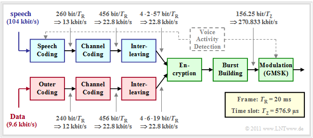
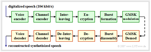
Below you can see the block diagram of the GSM transmission system at the transmitting end, which is
- is suitable for both digitized speech signals $($sampling rate: $8 \ \rm kHz$, quantization: $13$ bit ⇒ data rate: $104 \ \rm kbit/s)$
- as well as being suitable for $9.6 \ \rm kbit/s$ data signals.
Components for voice are shown in blue, those for data in red, and common blocks in green.
Here is a brief description of each component:
- Speech signals are compressed by speech coding from $104 \ \rm kbit/s$ to $13 \ \rm kbit/s$ - i.e. by a factor $8$. The bit rate given in the graph is for the full rate codec, which delivers $($duration $T_{\rm R} = 20\ \rm ms)$ exactly $260$ bits per speech frame.
- The AMR codec delivers in highest mode $12.2 \ \rm kbit/s$ $(244$ bits per speech frame$)$. However, the speech codec must also transmit additional information regarding the current mode, so the data rate before channel coding is also $13 \rm kbit/s$ .
- The task of the dashed Voice Activity Detection' is to decide whether the current voice frame actually contains a speech signal or just a voice pause during which the power of the transmit amplifier should be turned down.
- By channel coding redundancy is added again to allow error correction at the receiver. Per voice frame, the channel encoder outputs $456$ bits, resulting in the data rate $22.8 \ \rm kbit/s$ . The more important bits are specially protected.
- The interleaver scrambles the resulting bit sequence to reduce the influence of bundle errors. The $456$ input bits are split into four time frames of $114$ bits each. Thus, two consecutive bits are always transmitted in two different bursts.
- A data channel - marked in red in the figure - differs from a voice channel (marked in blue) only by the different input rate $(9.6 \ \rm kbit/s$ instead of $104 \ \rm kbit/s)$ and the use of a second, outer channel encoder instead of the speech encoder.
The components highlighted in green apply equally to voice and data transmission. The first common system component for voice and data transmission in the block diagram of the GSM transmitter is the encryption, which is intended to prevent unauthorized persons from gaining access to the data.
There are two fundamentally different encryption methods:
- Symmetric encryption: This knows only one secret key, which is used both for encrypting and enciphering the messages in the sender and for decrypting and deciphering them in the receiver. The key must be generated prior to communication and exchanged between the communication partners via a secure channel. The advantage of this encryption method used in conventional GSM is that it works very quickly.
- Asymmetric encryption: This method uses two independent but matching asymmetric keys. It is not possible to use one key to calculate the other. The "Public Key" is publicly available and is used for encryption. The "Private Key" is secret and used for decryption. In contrast to the symmetric encryption methods, the asymmetric methods are much slower, but also offer higher security.
The second green block is the bursting, where there are different burst types. In Normal Burst the $114$ encoded, scrambled and encrypted bits are mapped to $156.25$ bits by adding Guard Period, signaling bits, etc. These are transmitted within a time slot of duration $T_{\rm Z} = 576.9 \rm µ s$ by means of the modulation method "GMSK". This results in the gross data rate $270.833 \ \rm kbit/s$.
At the receiver there are in reverse order the blocks
- Demodulation,
- burst decomposition,
- decryption,
- de-interleaving,
- channel decoding,
- speech decoding.
In the next sections all blocks of the above transmission scheme are presented in detail.
Coding for speech signals
Uncoded radio data transmission leads to bit error rates in the percentage range. However, with Channel Coding some transmission errors can be detected or even corrected at the receiver. The bit error rate can thus be reduced to values smaller than $10^{-5}$.
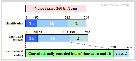
First, we consider GSM channel coding for voice channels, assuming as speech coder the "Full Rate Codec" . The channel coding of a voice frame of $20\ \rm ms$ duration is done in four consecutive steps according to the diagram.
From the description in chapter "Speech Coding" it can be seen that not all $260$ bits have the same influence on the subjectively perceived voice quality.
- Therefore, the data are divided into three classes according to their importance: The $50$ most important bits form the Class 1a, other $132$ are assigned to Class 1b and the remaining $78$ bits result in the rather unimportant Class 2.
- In the next step, a three-bit long "Cyclic Redundancy Check" (CRC) checksum is calculated for the $50$ particularly important bits of class 1a using a feedback shift register. The generator polynomial for this CRC check is:
- $$G_{\rm CRC}(D) = D^3 + D +1\hspace{0.05cm}. $$
- Subsequently, four (yellow) tail bits "0000" are added to the total of $185$ bits of class 1a and 1b including the three (red drawn) CRC parity bits. These four bits initialize the four memory registers of the following convolutional code with $0$ each, so that for each language frame a defined status can be assumed.
- The convolutional code with code rate $R_{\rm C} = 1/2$ doubles these $189$ most important bits to $378$ bits and thus significantly protects them against transmission errors. Then the $78$ bits of the less important class 2 are appended unprotected.
- This way, after channel coding, there are exactly $456$ bits per $20 \ \rm ms$ language frame. This corresponds to a (coded) data rate of $22.8\ \rm kbit/s$ compared to $13\ \rm kbit/s$ after speech coding. The effective channel coding rate is thus $260/456 = 57\%$.
Interleaving for speech signals
The result of convolutional decoding depends not only on the frequency of the transmission errors, but also on their distribution. To achieve good correction results, the channel should not have any memory, but should provide statistically independent bit errors as far as possible.
In mobile radio systems, however, transmission errors usually occur in blocks (error bursts) . By using the interleaving technique, such bundle errors are evenly distributed over several bursts and thus their effects are mitigated.
For a voice channel, the interleaver works in the following way:
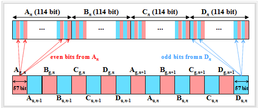
- The $456$ input bits per speech frame are divided into four blocks of $114$ bits each according to a fixed algorithm. We denote these for the $n$-th speech frame by $A_n$, $B_n$, $C_n$ and $D_n$. The index $n-1$ denotes the preceding frame and $n+1$ the succeeding one.
- The block $A_n$ is further divided into two sub-blocks $A_{{\rm g},\hspace{0.05cm}n}$ and $A_{{\rm u},\hspace{0.05cm}n}$ of $57$ bits each, where $A_{{\rm g},\hspace{0.05cm}n}$ denote only the even bit positions and $A_{{\rm u},\hspace{0.05cm}n}$ denote the odd bit positions of $A_n$ . In the graph, $A_{{\rm g},\hspace{0.05cm}n}$ and $A_{{\rm u},\hspace{0.05cm}n}$ can be recognized by the red and blue backgrounds, respectively.
- The subblock $A_{{\rm g},\hspace{0.05cm}n}$ of the $n$-th language frame is identified with the block $A_{{\rm u},\hspace{0.05cm}n-1}$ of the previous frame and gives the $114$ payload of a normal burst: $\left (A_{{\rm g},\hspace{0.05cm}n}, A_{{\rm u},\hspace{0.05cm}n-1}\right )$. The same applies to the next three bursts: $\left (B_{{\rm g},\hspace{0.05cm}n}, B_{{\rm u},\hspace{0.05cm}n-1}\right )$, $\left (C_{{\rm g},\hspace{0.05cm}n}, C_{{\rm u},\hspace{0.05cm}n-1}\right )$, $\left (D_{{\rm g},\hspace{0.05cm}n}, D_{{\rm u},\hspace{0.05cm}n-1}\right )$.
- In the same way, the odd subblocks of the $n$-th language frame are nested with the even sub-blocks of the following frame: $\left (A_{{\rm g},\hspace{0.05cm}n+1}, A_{{\rm u},\hspace{0.05cm}n}\right )$, ... , $\left (D_{{\rm g},\hspace{0.05cm}n+1}, D_{{\rm u},\hspace{0.05cm}n}\right )$.
$\text{Conclusion:}$ The scrambling type described here is called block-diagonal interleaving here specifically of degree $8$:
- This reduces the susceptibility to bunching errors.
- So two consecutive bits of a data block are never sent directly after each other.
- Multi-bit errors occur in isolation after the de-interleaver and can thus be corrected more effectively.
Encoding and interleaving for data signals
For GSM data transmission, each subscriber only has a net data rate of $9.6\ \rm kbit/s$ available. Two methods are used for error protection:
- Forward Error Correction (FEC) is implemented at the physical layer by applying convolutional codes.
- Automatic Repeat Request (ARQ); where defective packets that cannot be corrected are re-requested at the link layer.
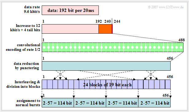
The graph illustrates channel coding and interleaving for the data channel with $9.6\ \rm kbit/s$, which in contrast to the channel coding of the voice channel $($with bit error rate $10^{-5}$... $10^{-6})$ allows an almost error-free reconstruction of the data:
- The data bit rate of $9.6\ \rm kbit/s$ is first increased in Terminal Equipment the mobile station by $25\%$ to $12\ \rm kbit/s$ through non-GSM specific channel coding to allow error detection in circuit switched networks.
- In data transmission, all bits are equivalent, so unlike speech channel coding, there are no classes. The $240$ bits per $20 \rm ms$ time frame are combined together with four tailbits $0000$ to form a single data frame.
- These $244$ bits are doubled to $488$ bits by a convolutional encoder of rate $1/2$ as in voice channels. Two code symbols are generated per incoming bit, for example according to the generator polynomials $G_0(D) = 1 + D^3 + D^4$ and $G_1(D) = 1 + D + D^3 + D^4$:
- The following interleaver expects - just like a "speech interleaver" - only $456$ bits per frame as input. Therefore, from the $488$ bits at the output of the convolutional encoder still $32$ bits at the positions $15 - j - 4 \ ( j = 1$, ... ,$ 32 )$ are removed ("puncturing").
- Since data transmission is less time critical than voice transmission, a higher interleaving degree is chosen here. The $456$ bits are distributed over up to $24$ interleaver blocks of $19$ bits each, which would not be possible for voice services for reasons of real-time transmission.
- Then the $456$ bits are split into four consecutive Normal Bursts and sent. When packing in the bursts, groupings of even and odd bits are again formed, similar to interleaving in the voice channel.
Receiver side of the GSM link - Decoding
The GSM receiver (highlighted in yellow) includes GMSK demodulation, burst decomposition, decoding, de-interleaving, and channel and speech decoding.
Regarding the last two blocks in the above image, it should be noted:
- The decoding method is not prescribed by the GSM specification, but is left to the individual network operators. The performance depends on the error correction algorithm used.
- For example, in the decoding procedure Maximum Likelihood Sequence Estimation (MLSE), the most probable bit sequence is determined using the Viterbi algorithm or a MAP receiver (Maximum A-posteriori Probability) .
- After error correction, the Cyclic Redundancy Check' (CRC) is performed, where for the full rate codec the degree of the CRC generator polynomial used is $G= 3$ . This will detect all error patterns up to weight $3$ and all bundle errors up to length $4$.
- The CRC is used to decide the usability of each language frame. If the test result is positive, the speech signals are synthesized from the speech parameters $(260$ bits per frame$)$ in the subsequent speech decoder.
- If frames are failed, the parameters of earlier frames detected as correct are used for interpolation ⇒ error concealment. If several incorrect speech frames occur in succession, the output is continuously lowered to mute.
Exercises for the chapter
Exercise 3.7: Components of the GSM System
