Contents
OVERVIEW OF THE FIRST MAIN CHAPTER
This first chapter serves as an introduction to the whole topic, which is covered by the nine books of the series $\rm LNTww$ .
This chapter describes in detail:
- the tasks and the basic structure of a communication system,
- the main functional units (source, transmitter, channel, receiver and sink) of such a system, and finally
- a classification of the signals occurring in a communication system according to several evaluation criteria: deterministic or stochastic, energy or power limited, continuous or discrete time, continuous or discrete value, analog or digital.
At the end of the chapter follows a short summary about "Calculating with complex numbers".
Message - Information - Signal
One distinguishes basically between the terms "message" and "information", which are often used synonymously nowadays.
$\text{Example 1:}$ An e–mail from Mr. Maier to Mrs. Miller is always a "message". For Mrs. Miller, however, receiving this e–mail only means an information gain if she learns something new. The "information" transmitted by a message therefore depends to a great extent on the knowledge level of the recipient. In practice, the information contained in a message is rather small, especially in the field of telephony.
The transmission and storage of a message always requires an energetic or material carrier called "signal". Physically the representation of a message is done by signals, which can be of very different nature.
Possible appearances are:
- electrical signals (for example current and voltage curve),
- electromagnetic waves (for example in radio transmission),
- Progression of pressure, temperature or other physical quantities,
- acoustic signals (for example, output signal of a loudspeaker),
- optical signals (for example output signal of a laser).
$\text{Please note:}$
- The signals used for message transmission are usually time functions. This means that (at least) one of the signal parameters is dependent on the time parameter $t$. Such signal parameters are for example for a signal tone the amplitude ("volume") and the frequency ("pitch").
- In a message memory the time functions are often mapped to spatial functions of suitable physical quantities such as magnetization (magnetic band) or degree of blackening (film).
The set of all message signals can be cataloged by different criteria, as described in chapter Signal classification.
Block diagram of a message transmission system
ODER: Block diagram of a Communication system?
In the following diagram a message transmission system is shown schematically.
The individual system components have the following tasks:
- The message source returns the source signal $q(t)$, which shall be transmitted over the message channel to the spatially distant sink. The message source can be for example a computer, a radio station or a telephone participant.
- In most cases the source signal $q(t)$ itself is unsuitable for transmission and must first be converted into the signal $s(t)$ in a suitable manner. This process is called „modulation” and is performed by the transmitter . Therefore $s(t)$ is called the transmitted signal in the following.
- At transmission over the channel this signal $s(t)$ is changed in its form; at the same time more or less strong noise– and noise signals are added. The signal at the channel output and simultaneously at the receiver input is called the received signal $r(t)$.
- The receiver must undo the conversion made by the sender. If, for example, the low-frequency source signal $q(t)$ was converted to the higher-frequency transmitter signal $s(t)$ the receiver must also contain a demodulator and undo this conversion.
- The last block in the model above is the message sink. The sink signal $v(t)$ is like the transmitted signal $q(t)$ again low frequency. In the ideal case, however, which in practice (due to the unavoidable noise) can never be reached exactly, should apply for all times $v(t) = q(t)$ .
Message source
As examples for news sources or for the source signal $q(t)$ can be mentioned
- Audio signals, for example speech or music,
- Video signals, for example an analog television signal or an MPEG encoded streaming video,
- Data signals, for example the data stream of a USB interface or an email on the Internet,
- Measure–signals, for example for control or regulation in a production process.
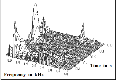
$\text{Example 2:}$ On the right you see the frequency-time representation of a speech signal.
- You can see the different frequency components in the kilohertz range at different times.
- By the way: This is a male speaker.
We thank Markus Kaindl [1], LNT/TUM, for providing the graphic.
A distinction is made between analog and digital news sources. The forms of description presented in this book „Signal Representation” apply equally to analog and digital signals.
The basic differences between analog and digital signals are
- discussed in the chapter Classification of signals ,and
- clarified throughout the video Analog and digital signals with examples.
Tasks of the transmitter
The essential task of the transmitter is to convert the source signal $q(t)$ into a transmitted signal $s(t)$ in such a way that it is adapted as well as possible to the transmission channel while maintaining the specified performance characteristics. For this purpose each transmitter contains corresponding functional units such as
- Transducer - for example a microphone for converting the physical quantity "pressure" (acoustic wave) into an electrical signal,
- Signal converter - for example from "analog" to "digital" using the components sampling, quantization and binary coding,
- Encoder for removing redundancy to data compression (source coding) or for systematically adding redundancy, which can be used at the receiver for error detection and/or error correction (channel coding)
- Modulator for adaptation to the transmission channel - for example a frequency conversion by means of amplitude, phase or frequency modulation or the corresponding digital methods ASK, PSK or FSK.
Depending on the application, the performance characteristics mentioned above mean that very specific properties are required for signal transmission.
Such features are for example:
- Power limitation - due to the discussions on the topic „electrosmog” highly topical,
- Bandwidth efficiency - the UMTS–auction in 2000 has shown what amounts are involved,
- distance or range - unfavorable values increase the infrastructure costs
- Transmission quality - for example a high signal–to–signal-to-noise ratio or a low error rate.
Communication channel
The transmission medium with its physical properties plays an essential role in the feasibility of certain transmission properties.
Examples of transmission media are:
- electrical cables, for example copper wire, twisted pair,
- Coaxial cable, for example antenna line or cable network,
- Fiber optic cables, for example multimode and single mode fiber optic,
- Radio channels, for example broadcasting, mobile and satellite radio.
$\text{Please note:}$ These transmission media are not ideal in practice and impair the transmission.
This means: The received signal $r(t)$ is different from the transmitted signal $s(t)$, possibly due to
- the channel attenuation,
- of delays on the channel,
- of linear and non-linear distortions.
In addition, the channel transmission properties can change significantly over time („time variance”, example: mobile radio).
In addition, the interfering signals that occur during signal transmission must always be taken into account. Here one can give the following examples:
- Noise signals - for example resistance and semiconductor noise,
- Pulse interference - for example power lines, spark interference and discharges,
- adjacent channel interference (crosstalk of other users, interference, cross modulation).
You will find basic information about modeling the message channel in general and the simple AWGN channel in the video Eigenschaften des Übertragungskanals.
Receiver - Message sink
As examples of the news sinks we can mention
- Eye and ear of man,
- Video recorder and call recorder,
- a smartphone that downloads a file from the Internet, or
- A control system that processes received measurement and dash signals.
To ensure that at least in the - in practice however never attainable - ideal case the sink signal $v(t)$ could coincide with the source signal $q(t)$ all measures taken on the transmission side must be reversed by the receiver.
Corresponding functional units of the recipient are:
- Transducer - for example a speaker to convert an electric signal into an acoustic signal (counterpart of the microphone),
- Signal reset - for example the reconstruction of the analog signal from the digital samples (D/A converter ⇒ counterpart to A/D converter),
- Decoding - for example with the possibility of error detection and error correction (counterpart of the channel coder)
Another important task of the receiver is to eliminate as much as possible the signal distortions and interference that occur during transmission.
The realization of such system components for transmitters and receivers is done by different electrical networks and assemblies. Here, too, some functional units can be named as examples:
- Amplifier, filter and equalizer,
- Oscillators and nonlinear components for (de-)modulation and synchronization,
- digital signal processing components and signal processors.
Signal distortions
It has already been mentioned that ideally $v(t) = q(t)$ should be valid. However, as with any real transmission channel $r(t) \neq s(t)$, the sink signal $v(t)$ will be different from the source signal $q(t)$ . Here are some examples:
$\text{Definition:}$ One speaks of noise, if for the sink signal applies:
- \[ v(t)=q(t)+n(t).\]
The additive noise component $n(t)$ is always of stochastic nature and usually has no relation to the message signal $q(t)$. Such a noise term is inevitable for every transmission.
$\text{Definition:}$ The transmission is distortion-free if the sink signal is as follows:
- \[v(t)=a \cdot q(t-\tau)+n(t).\]
In this case the sink signal differs from the source signal - except for the noise component $n(t)$ - only the (same for all frequencies) attenuation factor $\alpha$ and the (also the same for all frequencies) transit time $\tau$.
$\text{Definition:}$ If the equation $v(t)=a\cdot q(t-\tau)+n(t)$ is not fulfilled, then there are distortions . One distinguishes between
as described in the book Linear and Time Invariant Systems
In this context we refer to the learning video Linear and nonlinear distortions.
Here again in slightly different words:
- The attenuation factor $\alpha$ only causes the signal $v(t)$ to be slightly "quieter" than $q(t)$; but both signals have the same shape.
- The runtime $\tau$ causes the signal $v(t)$ to arrive at the receiver later than $q(t)$ was sent
Both effects are not particularly disturbing for a unidirectional transmission For example, one can still speak of a live transmission if the television picture arrives delayed by (a fraction of) seconds.
With a bidirectional transmission however, a long runtime can lead to problems. During a telephone call, the two conversation partners then start talking to each other.
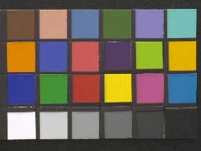
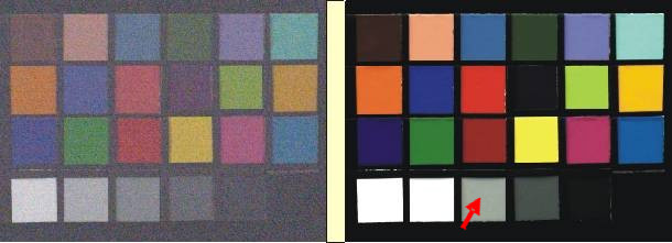
$\text{Example 3:}$ The terms used here shall now be clarified by an image signal.
On the right you see as original image a color template with $291 × 218$ pixels and $24$ bit color depth. Of the possible $2^{24} = 16\hspace{0.08cm} 777\hspace{0.08cm} 216$ only a few colors are used here.
- In the lower left image, the signal is superposed with additive noise $n(t)$ which is perceived as "snow".
- The lower right image shows the influence of (non-linear) distortions, which lead to a distortion of both brightness values and color information at the selected setting of the CCD camera.
- In the marked field of the gray staircase, the brightness corresponds approximately to the original image (above).
- On the other hand, other fields appear as too light or too dark or filled with missing colors.
- Noise effects play no role in the right image as opposed to the left image.
Exercises for the chapter
Exercise 1.1Z: ISDN Connection
List of sources
- ↑ Kaindl, M.: Kanalcodierung für Sprache und Daten in GSM-Systemen. Dissertation. Lehrstuhl für Nachrichtentechnik, TU München. VDI Fortschritt-Berichte, Reihe 10, Nr. 764, 2005.


