Contents
- 1 # OVERVIEW OF SECOND MAIN CHAPTER #
- 2 Description in the frequency domain
- 3 Description in the time domain
- 4 Ring modulator
- 5 AM signals and spectra with a harmonic input signal
- 6 Double-Sideband Amplitude Modulation with carrier
- 7 Describing DSB-AM using the analytical signal
- 8 Amplitudenmodulation durch quadratische Kennlinie
- 9 Aufgaben zum Kapitel
# OVERVIEW OF SECOND MAIN CHAPTER #
$\Rightarrow \hspace{0.5cm}\text{We are just beginning the English translation of this chapter.}$
After some general explanations of modulation and demodulation, a detailed description of amplitude modulation and their associated demodulators. This chapter deals in detail with:
- the description and realization of double-sideband amplitude modulation (DSB–AM) in the frequency and time domains,
- the characteristics of a synchronous demodulator and the possible applications of an envelope demodulator,
- the similarities/differences of single-sideband modulation compared to DSB-AM and modified AM methods.
Description in the frequency domain
We consider the following problem: a message signal $q(t)$, whose spectrum $Q(f)$ is bandlimited to the range $\pm B_{\rm NF}$ (subscript NF from German "Niederfrequenz" ⇒ low frequency), is to be shifted to a higher frequency range where the channel frequency response $H_{\rm K}(f)$ has favorable characteristics, using a harmonic oscillation of frequency $f_{\rm T}$, which we will refer to as the carrier signal $z(t)$ .
The diagram illustrates the task, with the following simplifying assumptions:
- The spectrum $Q(f)$ drawn here is schematic. It states that only spectral components in the range $|f| ≤ B_{\rm NF}$ are included in $q(t)$ . $Q(f)$ could also be a line spectrum.
- Let the channel be ideal in a bandwidth range $B_{\rm K}$ around frequency $f_{\rm M}$ , that is, let $H_{\rm K}(f) = 1$ for $|f - f_{\rm M}| ≤ B_{\rm K}/2.$ Noise interference is ignored for now.
- Let the carrier signal be cosine $($phase $ϕ_T = 0)$ and have amplitude $A_{\rm T} = 1$ (without a unit). Let the carrier frequency $f_{\rm T}$ be equal to the center frequency of the transmission band.
- Thus, the spectrum of the carrier signal $z(t) = \cos(ω_{\rm T} · t)$ (plotted in green in the graph) is:
- $$Z(f) = {1}/{2} \cdot \delta (f + f_{\rm T})+{1}/{2} \cdot \delta (f - f_{\rm T})\hspace{0.05cm}.$$
Those familiar with the laws of spectral transformation and in particular with the Convolution Theorem can immediately give a solution for the spectrum $S(f)$ of the modulator output signal:
- $$S(f)= Z(f) \star Q(f) = 1/2 \cdot \delta (f + f_{\rm T})\star Q(f)+1/2 \cdot \delta (f - f_{\rm T})\star Q(f) = 1/2 \cdot Q (f + f_{\rm T})+ 1/2 \cdot Q(f - f_{\rm T}) \hspace{0.05cm}.$$
$\text{Please note:}$ This equation takes into account that the convolution of a shifted Dirac function $δ(x – x_0)$ with an arbitrary function $f(x)$ yields the shifted function $f(x - x_0)$ .
The diagram displays the result. One can identify the following characteristics:
- Due to the system-theoretic approach with positive and negative frequencies, $S(f)$ is composed of two parts around $\pm f_{\rm T}$ , each of which have the same shape as $Q(f)$ .
- The factor $1/2$ results from the carrier amplitude $A_{\rm T} = 1$. Thus, $s(t = 0) = q(t = 0)$, and the integrals over their spectral functions $S(f)$ and $Q(f)$ must also be equal.
- The channel bandwidth $B_{\rm K}$ must be at least twice the signal bandwidth $B_{\rm NF}$, which gives the name "double-sideband amplitude modulation"(DSB–AM).
- It should be noted that $B_{\rm NF}$ and $B_{\rm K}$ are absolute and non-equivalent bandwidths. The latter are defined over rectangles of equal area and are denoted by $Δf_q$ and $Δf_{\rm K}$ in our tutorial, respectively.
- The Spectral function $S(f)$ does not include any Dirac-lines at the carrier frequency $(\pm f_{\rm T})$. Therefore, this method is also referred to as "DSB-AM without carrier".
- The frequency components above the carrier frequency $f_{\rm T}$ are called the upper sideband (USB), and those below $f_{\rm T}$ are the lower sideband (LSB).
Description in the time domain
Adapting the notation and nomenclature to this problem, the convolution theorem reads:
- $$S(f) = Z(f) \star Q(f)\hspace{0.2cm}\bullet\!\!-\!\!\!-\!\!\!-\!\!\circ\, \hspace{0.2cm} s(t) = q(t) \cdot z(t) = q(t) \cdot \cos(\omega_{\rm T}\cdot t + \phi_{\rm T})\hspace{0.05cm}.$$
This result is still true if the restrictions made on the last page $($real-valued spectrum $Q(f)$, carrier phase $ϕ_{\rm T} = 0)$ are removed. In general, this results in a complex-valued spectral function $S(f)$.
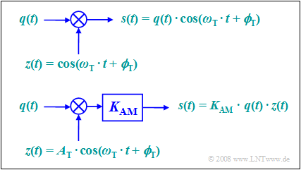
According to this equation, two models can be given for double-sideband amplitude modulation. These are to be interpreted as follows:
- The first model directly describes the relationship given above, where here the carrier $z(t) = \cos(ω_{\rm T}t + ϕ_{\rm T})$ is applied without a unit.
- The second model is more in line with the physical conditions, after each signal also has a unit. If $q(t)$ and $z(t)$ are voltages respectively, the model still needs to provide a scaling with the modulator constant $K_{\rm AM}$ (unitso that the output signal $s(t)$ also represents a voltage waveform.
- If we set $K_{\rm AM} = 1/A_{\rm T}$, both models are the same. In the following, we will always assume the simpler model.
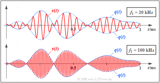
$\text{Example 1:}$ The graph shows in red the transmitted signals $s(t)$ for DSB–AM with two different carrier frequencies.
- The source signal $q(t)$ with bandwidth $B_{\rm NF} = 4\text{ kHz}$, which is the same in both cases, is drawn in solid blue and the signal $-q(t)$  is dashed.
- The carrier signal $z(t)$ has a cosine shape in both cases.
- In the upper image, the carrier frequency is $f_{\rm T} = 20\text{ kHz}$ and the lower image $f_{\rm T} = 100\text{ kHz}$.
Ring modulator
One possibility to realize "double sideband amplitude modulation with carrier suppression" is offered by a so-called ring modulator, also known as double push-pull diode modulator. Below you can see the circuit on the left and a simple functional diagram on the right.
Without claiming to be complete, the principle can be stated as follows:
- Let the amplitude of the harmonic carrier oscillation $z(t)$ be much larger than the maximum value $q_{\rm max}$ of the message signal $q(t)$. Thus, all diodes are operated as switches.
- When the half-wave of the carrier is positive $(z(t) > 0)$ the two magenta diodes conduct while the light green ones block. Thus, without considering losses, $s(t) = q(t)$ holds.
- For a negative half-wave, the light green diodes conduct and the diodes in the longitudinal branches block. As can be seen from the right image,;$s(t) = \ – q(t)$ holds for this lower switch position.
- Due to the operation of this switch, the harmonic oscillation $z(t)$ can also be replaced by a periodic square wave signal with identical period duration:
- $$z_{\rm R}(t) = \left\{ \begin{array}{c} +1 \\ -1 \\ \end{array} \right.\quad \begin{array}{*{10}c} {\rm{for}} \\ {\rm{for}} \\ \end{array}\begin{array}{*{20}c} {z(t) >0,} \\ {z(t) <0.} \\ \end{array}$$
- The modulated signal $s(t)$ is then obtained as the product of the message signal $q(t)$ and this square wave signal $z_{\rm R}(t)$, whereas in ideal DSB-AM one multiplies by a cosine signal.
- The carrier $z(t)$ is not itself included in the signal $s(t)$. Since this is supplied via the center taps of the transformers, the induced voltages cancel out ("DSB-AM without a carrier").
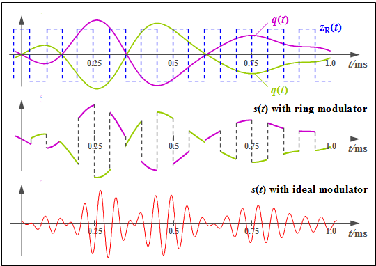
$\text{Example 2:}$ Now we will explain the mode of operation of a ring modulator using typical signal characteristics. Let the carrier frequency be $f_{\rm T} = 10\text{ kHz}$.
- The top graph shows the signals $q(t)$ and $-q(t)$ as magenta and light green waveforms respectively.
- The bipolar square wave signal $z_{\rm R}(t)$ is shown in blue dashes, and takes the values $±1$ .
- The middle chart shows the modulated signal from the ring modulator:
- $$s_{\rm RM}(t) = q(t) · z_{\rm R}(t).$$
- For comparison, the conventional DSB-AM signal is shown in the bottom graph:
- $$s(t) = q(t) · \cos(ω_{\rm T} · t).$$
One can see significant differences, but these can be compensated for in a simple way:
- The Fourier series representation of the periodic square wave signal $z_{\rm R}(t)$ is:
- $$z_{\rm R}(t) = \frac{4}{\pi} \cdot \cos(\omega_{\rm T}\cdot t)-\frac{4}{3\pi} \cdot \cos(3\omega_{\rm T}\cdot t) +\frac{4}{5\pi} \cdot \cos(5\omega_{\rm T}\cdot t)- \text{ ...}$$
- The associated spectral function consists of Dirac lines at $±f_{\rm T}, ±3f_{\rm T}, ±5f_{\rm T}$, etc. Convolution with $Q(f)$ leads to the spectral function (the subscript stands for "ring modulator"):
- $$S_{\rm RM}(f) = \frac{2}{\pi} \cdot Q (f \pm f_{\rm T})-\frac{2}{3\pi} \cdot Q (f \pm 3f_{\rm T})+\frac{2}{5\pi} \cdot Q (f \pm 5f_{\rm T}) -\text{ ...} \hspace{0.05cm}$$
- From this, it can be seen that by appropriately band-limiting $($for example, to $±2f_{\rm T})$ and attenuating with $π/4 ≈ 0.785$ the familiar DSB-AM spectrum can be obtained:
- $$S(f) = {1}/{2} \cdot Q (f \pm f_{\rm T})\hspace{0.05cm}.$$
Here it must be taken into account that in the above reasoning, $B_{\rm NF} \ll f_{\rm T}$ can always be assumed.
AM signals and spectra with a harmonic input signal
Now we will consider a special case, which is important for testing purposes, where not only the carrier signal $z(t)$ is a harmonic oscillation, but also the message signal to be modulated $q(t)$ :
- $$\begin{align*}q(t) & = A_{\rm N} \cdot \cos(\omega_{\rm N} \cdot t + \phi_{\rm N})\hspace{0.05cm}, \\ \\ z(t) & = \hspace{0.15cm}1 \hspace{0.13cm} \cdot \hspace{0.1cm}\cos(\omega_{\rm T} \cdot t + \phi_{\rm T})\hspace{0.05cm}.\end{align*}$$
Please note: since we are describing modulation processes, the phase term is used with a plus sign in the above equations.
- Thus, $ϕ_{\rm N} = - 90^\circ$ represents a sinusoidal input signal $q(t)$ and $ϕ_{\rm T} = - 90^\circ$ denotes a sinusoidal carrier signal $z(t)$.
- Therefore, the equation for the modulated signal is:
- $$s(t) = q(t) \cdot z(t) = A_{\rm N} \cdot \cos(\omega_{\rm N} t + \phi_{\rm N})\cdot \cos(\omega_{\rm T} t + \phi_{\rm T})\hspace{0.05cm}.$$
This equation can be transformed using the trigonometric addition theorem:
- $$s(t) = A_{\rm N}/{2} \cdot \cos \big [(\omega_{\rm T} +\omega_{\rm N})\cdot t + \phi_{\rm T}+ \phi_{\rm N} \big ] + A_{\rm N}/{2} \cdot \cos \big [(\omega_{\rm T} -\omega_{\rm N})\cdot t + \phi_{\rm T}- \phi_{\rm N} \big ]\hspace{0.05cm}.$$
- For cosinusoidal signals $(ϕ_{\rm T} = ϕ_{\rm N} = 0)$ , this equation simplifies to
- $$s(t) = {A_{\rm N}}/{2} \cdot \cos\big[(\omega_{\rm T}+\omega_{\rm N})\cdot t\big] + {A_{\rm N}}/{2} \cdot \cos\big[(\omega_{\rm T} -\omega_{\rm N})\cdot t \big]\hspace{0.05cm}.$$
- Using a Fourier transform we arrive at the spectral function:
- $$S(f) = {A_{\rm N}}/{4} \cdot \big[\delta ( f - f_{\rm T} - f_{\rm N})+\delta ( f + f_{\rm T} + f_{\rm N})\big)] + {A_{\rm N}}/{4} \cdot \big[ \delta ( f - f_{\rm T}+ f_{\rm N})+\delta ( f+ f_{\rm T} - f_{\rm N} ) \big]\hspace{0.05cm}.$$
This result, which would also have been arrived at via convolution, states:
- The spectrum consists of four Dirac lines at frequencies $±(f_{\rm T} + f_{\rm N})$ and $±(f_{\rm T} - f_{\rm N})$, where in both bracket expressions the first Dirac function indicates the one for positive frequencies.
- The weights of all Dirac functions are equal and each is $A_{\rm N}/4$. The sum of these weights - that is, the integral over $S(f)$ – is equal to the signal value $s(t = 0) = A_{\rm N}$.
- The Dirac lines remain for $ϕ_{\rm T} ≠ 0$ and/or $ϕ_{\rm N} ≠ 0$ at the same frequencies. However, complex rotation factors must then be added to the weights $A_{\rm N}/4$ .
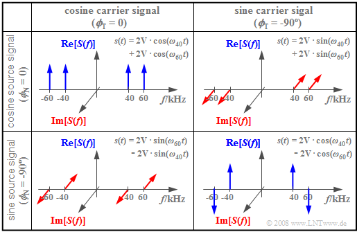
$\text{Example 3:}$ The following diagram shows the spectral functions $S(f)$ for different values of $ϕ_{\rm T}$ and $ϕ_{\rm N}$, respectively. The other parameters are assumed to be $f_{\rm T} = 50\text{ kHz}$, $f_{\rm N} = 10\text{ kHz}$ and $A_{\rm N} = 4\text{ V}$ . Thus, the magnitudes of all Dirac lines are $A_{\rm N}/4 = 1\text{ V}$.
- The upper left image shows the case just discussed: both the carrier and the message signal are cosine. Thus, the amplitude modulated signal $s(t)$ s composed of two cosine oscillations with $ω_{60} = 2 π · 60\text{ kHz}$ and $ω_{40} = 2 π · 40\text{ kHz}$ .
- For the other three constellations, at least one of the signals $q(t)$ or $z(t)$ sinusförmig, is sinusoidal, so that $s(0) = 0$ always holds. Thus, for these spectra, the sum of the four impulse weights each add up to zero.
- The bottom right image depicts $s(t) = A_{\rm N} · \sin(ω_{\rm N} t) · \sin(ω_{\rm T}t)$. Multiplying two odd functions yields the even function $s(t)$ and thus a real spectrum $S(f)$. In contrast, the other two constellations each result in imaginary spectral functions.
Double-Sideband Amplitude Modulation with carrier
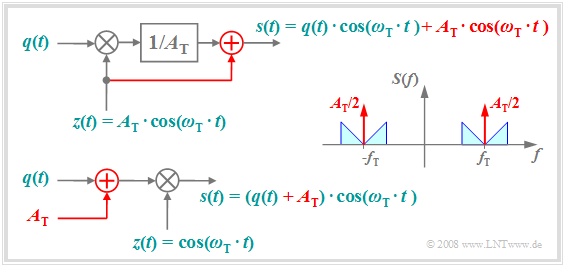
The following diagram shows how to get from "DSB-AM without a carrier" to the better known variant "DSB-AM with carrier". This has the advantage that the demodulator can be realized much more easily and cheaply by a simple manipulation at the transmitter.
The diagram is to be interpreted as follows:
- The top plot shows the physical model of the "DSB-AM with carrier", with changes from the "DSB-AM without a carrier" highlighted in red.
- The carrier signal $z(t) = A_{\rm T} · \cos(ω_{\rm T} · t)$ is added to the signal $s(t)$ , which causes two additional Dirac functions in the spectrum $±f_{\rm T}$ bewirkt, ach with impulse weight $A_{\rm T}/2$.
- Adding the DC signal $A_{\rm T}$ to the source signal and then multiplying by the dimensionless carrier $z(t)$ as shown in the lower sketch results in the same signal $s(t)$ and spectrum $S(f)$ as above.
- Thus, the second representation is equivalent to the upper model. In both cases the carrier phase is only set to $ϕ_{\rm T} = 0$ for the sake of simplified presentation.
$\text{Example 4:}$ The Double-sideband with carrier still finds its main application in radio transmissions for
- long wave $($frequency range $\text{30 kHz}$ ... $\text{300 kHz})$,
- medium wave $($frequency range $\text{300 kHz}$ ... $\text{3 MHz})$,
- short wave $($frequency range $\text{3 MHz}$ ... $\text{30 MHz})$.
However, these frequencies are increasingly being made available for digital applications, for example Digital Video Broadcast (DVB).
An application of Double-sideband amplitude modulation without a carrier exists for example in FM stereo broadcasting:
- Here, the differential signal between the two stereo channels is amplitude modulated without a carrier at $\text{39 kHz}$ .
- Then the sum signal of the two channels $($each in the range $\text{30 Hz}$ ... $\text{15 kHz})$ is combined with an auxiliary carrier at $\text{19 kHz}$ and the dofferential signal and frequency modulated.
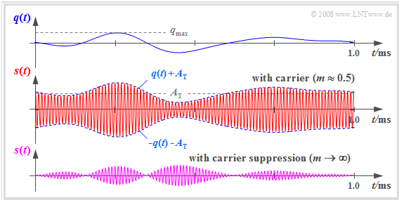
$\text{Example 5:}$ The following signal waveforms are intended to further clarify the principle of the "DSB-AM with carrier".
- Above is a section of the source signal $q(t)$ in the frequency range $\vert f \vert \le 4\text{ kHz}$ .
- $s(t)$ is obtained by adding the DC component nbsp;$A_{\rm T}$ is added to $q(t)$ and multiplying this summed signal by the carrier signal $z(t)$ of frequency $f_{\rm T} = 100\text{ kHz}$ .
- Below is the transmitted signal of the "DSB-AM without carrier" for comparison.
A comparison of these signal waveforms shows:
- By adding the DC component $A_{\rm T}$ the message signal $q(t)$ can now be seen in the envelope of $s(t)$ .
- Thus, envelope demodulation can be applied, which is easier and cheaper to implement than coherent synchronous demodulation.
- However, a prerequisite for the application of the envelope demodulator is a modulation depth $m <1$. This is defined as follows:
- $$m = \frac{q_{\rm max} }{A_{\rm T} } \hspace{0.3cm}{\rm mit}\hspace{0.3cm} q_{\rm max} = \max_{t} \hspace{0.05cm} \vert q(t) \vert\hspace{0.05cm}.$$
- The advantage of a simpler demodulator is traded off with a much higher transmission power, since the power contribution of the carrier cannot be used for demodulation.
- Furthermore, care must be taken to ensure that the source signal does not contain a DC component, since this would be masked by the carrier. For speech and music signals, however, this is not a major restriction.
Describing DSB-AM using the analytical signal
In the further course of this chapter, for the sake of simplifying the graphs, the spectrum $S_+(f)$ of the analytical signal is usually given instead of the actual, physical spectrum $S(f)$ .
As an example, let us consider a "DSB-AM with carrier" and the following signals:
- $$\begin{align*}s(t) & = \left(q(t) + A_{\rm T}\right) \cdot \cos(\omega_{\rm T}\cdot t + \phi_{\rm T})\hspace{0.05cm}, \\ \\ q(t) & = A_{\rm N} \cdot \cos(\omega_{\rm N}\cdot t + \phi_{\rm N})\hspace{0.05cm}.\end{align*}$$
Then the corresponding analytical signal is:
- $$s_+(t) = A_{\rm T} \cdot {\rm e}^{{\rm j}\hspace{0.03cm} \cdot \hspace{0.01cm}(\omega_{\rm T}\cdot \hspace{0.02cm}t \hspace{0.05cm}+ \hspace{0.05cm}\phi_{\rm T})}+ \frac{A_{\rm N}}{2} \cdot {\rm e}^{{\rm j}\hspace{0.03cm} \cdot \hspace{0.01cm}((\omega_{\rm T} \hspace{0.05cm}+ \hspace{0.05cm} \omega_{\rm N} )\hspace{0.02cm}\cdot \hspace{0.02cm}t \hspace{0.05cm}+ \hspace{0.05cm} \phi_{\rm T}+ \phi_{\rm N})} + \frac{A_{\rm N}}{2} \cdot {\rm e}^{{\rm j}\hspace{0.03cm} \cdot \hspace{0.01cm}((\omega_{\rm T} \hspace{0.05cm}- \hspace{0.05cm} \omega_{\rm N} )\hspace{0.02cm}\cdot \hspace{0.02cm}t \hspace{0.05cm}+ \hspace{0.05cm} \phi_{\rm T}- \phi_{\rm N})} \hspace{0.05cm}.$$
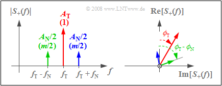
The corresponding spectral function $S_+(f)$ consists of three Dirac lines, each with complex weights corresponding to the graph:
- The left sketch shows the magnitude $|S_+(f)|$, where $A_{\rm T}$ indicates the weight of the carrier and $A_{\rm N}/2$ indicates the weights of USB (upper sideband) and LSB (lower sideband).
- The values normalized to $A_{\rm T}$ are given in parentheses. Since $q_{\rm max} = A_{\rm N}$ holds here, the modulation depth $m = A_{\rm N}/A_{\rm T}$ gives $m/2$ as the normalized weights of both the upper and lower sideband.
- The right sketch depicts the direction of the frequency axis and shows the phase angles of carrier $(ϕ_{\rm T})$, LSB $(ϕ_{\rm T} – ϕ_{\rm N})$ and USB $(ϕ_{\rm T} + ϕ_{\rm N})$.
Amplitudenmodulation durch quadratische Kennlinie
Nichtlinearitäten sind in der Nachrichtentechnik meist unerwünscht und störend. Wie im Kapitel Nichtlineare Verzerrungen des Buches „Lineare zeitinvariante Systeme” dargelegt, führen sie dazu, dass
- das Superpositionsprinzip nicht mehr anwendbar ist,
- das Übertragungsverhalten von der Größe des Eingangssignals abhängt, und
- die Verzerrungen von nichtlinearer Art und damit irreversibel sind.
Eine Nichtlinearität der allgemeinen Form
- $$y(t) = c_0 + c_1 \cdot x(t) + c_2 \cdot x^2(t)+ c_3 \cdot x^3(t) + \text{...}$$
kann aber auch zur Realisierung einer ZSB–AM genutzt werden. Unter der Voraussetzung, dass
- nur die Koeffizienten $c_1$ und $c_2$ vorhanden sind, und
- das Eingangssignal $x(t) = q(t) + z(t)$ angelegt wird,
erhält man für das Ausgangssignal der Nichtlinearität:
- $$y(t) = c_1 \cdot q(t) + c_1 \cdot z(t) + c_2 \cdot q^2(t)+ 2 \cdot c_2 \cdot q(t)\cdot z(t)+ c_2 \cdot z^2(t)\hspace{0.05cm}.$$
Der erste, der dritte und der letzte Anteil liegen – spektral gesehen – bei $| f | ≤ 2 · B_{\rm NF}$ bzw. $| f | = 2 · f_{\rm T}$.
Entfernt man diese Signalanteile durch einen Bandpass und berücksichtigt $z(t) = A_{\rm T} · \cos(ω_{\rm T} · t)$, so erhält man die für „ZSB–AM mit Träger” typische Gleichung
(nur noch der zweite und der vierte Term):
- $$s(t) = c_1 \cdot A_{\rm T} \cdot \cos(\omega_{\rm T} \cdot t ) + 2 \cdot c_2 \cdot A_{\rm T} \cdot q(t)\cdot \cos(\omega_{\rm T} \cdot t )\hspace{0.05cm}.$$
Der Modulationsgrad ist bei dieser Realisierungsform durch die Koeffiziente $c_1$ und $c_2$ veränderbar:
- $$m = \frac{2 \cdot c_2 \cdot q_{\rm max}}{c_1} \hspace{0.05cm}.$$
Eine Diode und der Feldeffekttransistor besitzen mit guter Näherung eine solche quadratische Kennlinie und können zur Realisierung einer ZSB–AM genutzt werden. Kubische Anteile $(c_3 ≠ 0)$ und Nichtlinearitäten höherer Ordnung führen allerdings zu (großen) nichtlinearen Verzerrungen.
Aufgaben zum Kapitel
Aufgabe 2.1: ZSB-AM mit Cosinus? Oder mit Sinus?
Aufgabe 2.1Z: ZSB-AM ohne/mit Träger
Aufgabe 2.2Z: Leistungsbetrachtung
Aufgabe 2.3: ZSB–AM–Realisierung
Aufgabe 2.3Z: ZSB durch Nichtlinearität


