Contents
Channel coding theorem and channel capacity
We further consider a binary block code with
- $k$ information bits per block,
- code words of length $n$,
- resulting in the code rate $R=k/n$ with the unit "information bit/code symbol".
The ingenious information theorist Claude E. Shannon has dealt very intensively with the correctability of such codes already in 1948 and has given for this a limit for each channel which results from information-theoretical considerations alone. Up to this day, no code has been found which exceeds this limit, and this will remain so.
$\text{Shannon's channel coding theorem:}$ For each channel with channel capacity $C > 0$ there always exists (at least) one code whose error probability approaches zero as long as the code rate $R$ is smaller than the channel capacity $C$. The prerequisite for this is that the following holds for the block length of this code:
- $$n \to \infty.$$
Notes:
- The statement "The error probability approaches zero" is not identical with the statement "The transmission is error-free". Example: For an infinitely long sequence, finitely many symbols are corrupted.
- For some channels, even with $R=C$ the error probability still goes towards zero (but not for all).
The inverse of the channel coding theorem is also true and states:
$\text{Inverse:}$ If the code rate $R$ is larger than the channel capacity $C$, then an arbitrarily small error probability cannot be achieved in any case
.
To derive and calculate the channel capacity, we first assume a digital channel with $M_x$ possible input values $x$ and $M_y$ possible output values $y$. Then, for the mean mutual information – briefly, the "mutual information" – between the random variable $x$ at the channel input and the random variable $y$ at its output:
- \[I(x; y) =\sum_{i= 1 }^{M_X} \hspace{0.15cm}\sum_{j= 1 }^{M_Y} \hspace{0.15cm}{\rm Pr}(x_i, y_j) \cdot {\rm log_2 } \hspace{0.15cm}\frac{{\rm Pr}(y_j \hspace{0.05cm}| \hspace{0.05cm}x_i)}{{\rm Pr}(y_j)} = \sum_{i= 1 }^{M_X} \hspace{0.15cm}\sum_{j= 1 }^{M_Y}\hspace{0.15cm}{\rm Pr}(y_j \hspace{0.05cm}| \hspace{0.05cm}x_i) \cdot {\rm Pr}(x_i) \cdot {\rm log_2 } \hspace{0.15cm}\frac{{\rm Pr}(y_j \hspace{0.05cm}| \hspace{0.05cm}x_i)}{\sum_{k= 1}^{M_X} {\rm Pr}(y_j \hspace{0.05cm}| \hspace{0.05cm}x_k) \cdot {\rm Pr}(x_k)} \hspace{0.05cm}.\]
In the transition from the first to the second equation, the "Theorem of Bayes" and the "Theorem of Total Probability" were considered.
Further, it should be noted:
- The "binary logarithm" is denoted here with "log2". Partially, we also use "ld" ("logarithm dualis") for this in our learning tutorial.
- In contrast to the book "Information Theory" we do not distinguish in the following between the random variable $($upper case letters $X$ resp. $Y)$ and the realizations $($lower case letters $x$ resp. $y)$.
$\text{Definition:}$ The channel capacity introduced by Shannon gives the maximum mutual information $I(x; y)$ between the input variable $x$ and the output variable $y$:
- \[C = \max_{{{\rm Pr}(x_i)}} \hspace{0.1cm} I(X; Y) \hspace{0.05cm}.\]
The pseudo–unit "bit/channel use" must be added.
- Since the maximization of the mutual information $I(x; y)$ must be done over all possible (discrete) input distributions ${\rm Pr}(x_i)$,
- the channel capacity is independent of the input and thus a pure channel parameter.
- the channel capacity is independent of the input and thus a pure channel parameter.
Channel capacity of the BSC model
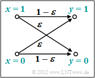
We now apply these definitions to the "BSC model" ("Binary Symmetric Channel"):
- \[I(x; y) = {\rm Pr}(y = 0 \hspace{0.03cm}| \hspace{0.03cm}x = 0) \cdot {\rm Pr}(x = 0) \cdot {\rm log_2 } \hspace{0.15cm}\frac{{\rm Pr}(y = 0 \hspace{0.03cm}| \hspace{0.03cm}x = 0)}{{\rm Pr}(y = 0)} + {\rm Pr}(y = 1 \hspace{0.03cm}| \hspace{0.03cm}x = 0) \cdot {\rm Pr}(x = 0) \cdot {\rm log_2 } \hspace{0.15cm}\frac{{\rm Pr}(Y = 1 \hspace{0.03cm}| \hspace{0.03cm}x = 0)}{{\rm Pr}(y = 1)} + \]
- \[\hspace{1.45cm} + \hspace{0.15cm}{\rm Pr}(y = 0 \hspace{0.05cm}| \hspace{0.05cm}x = 1) \cdot {\rm Pr}(x = 1) \cdot {\rm log_2 } \hspace{0.15cm}\frac{{\rm Pr}(Y = 0 \hspace{0.05cm}| \hspace{0.05cm}x = 1)}{{\rm Pr}(y = 0)} + {\rm Pr}(y = 1 \hspace{0.05cm}| \hspace{0.05cm}x = 1) \cdot {\rm Pr}(x = 1) \cdot {\rm log_2 } \hspace{0.15cm}\frac{{\rm Pr}(y = 1 \hspace{0.05cm}| \hspace{0.05cm}x = 1)}{{\rm Pr}(y = 1)} \hspace{0.05cm}.\]
The channel capacity is arrived at by the following considerations:
- Maximization with respect to the input distribution leads to equally probable symbols:
- \[{\rm Pr}(x = 0) = {\rm Pr}(x = 1) = 1/2 \hspace{0.05cm}.\]
- Due to the symmetry evident from the model, the following then holds simultaneously:
- \[{\rm Pr}(y = 0) = {\rm Pr}(y = 1) = 1/2 \hspace{0.05cm}.\]
- We also consider the BSC transmission probabilities:
- \[{\rm Pr}(y = 1 \hspace{0.05cm}| \hspace{0.05cm}x = 0) = {\rm Pr}(y = 0 \hspace{0.05cm}| \hspace{0.05cm}x = 1) = \varepsilon \hspace{0.05cm},\]
- \[{\rm Pr}(y = 0 \hspace{0.05cm}| \hspace{0.05cm}x = 0) = {\rm Pr}(y = 1 \hspace{0.05cm}| \hspace{0.05cm}x = 1) = 1-\varepsilon \hspace{0.05cm}.\]
- After combining two terms each, we thus obtain:
- \[C \hspace{0.15cm} = \hspace{0.15cm} 2 \cdot 1/2 \cdot \varepsilon \cdot {\rm log_2 } \hspace{0.15cm}\frac{\varepsilon}{1/2 }+
2 \cdot 1/2 \cdot (1- \varepsilon) \cdot {\rm log_2 } \hspace{0.15cm}\frac{1- \varepsilon}{1/2 }
\varepsilon \cdot {\rm ld } \hspace{0.15cm}2 - \varepsilon \cdot {\rm log_2 } \hspace{0.15cm} \frac{1}{\varepsilon }+ (1- \varepsilon) \cdot {\rm log_2 } \hspace{0.15cm} 2 - (1- \varepsilon) \cdot {\rm log_2 } \hspace{0.15cm}\frac{1}{1- \varepsilon}\]
- \[\Rightarrow \hspace{0.3cm} C \hspace{0.15cm} = \hspace{0.15cm} 1 - H_{\rm bin}(\varepsilon). \]
- Here, the "binary entropy function" is used:
- \[H_{\rm bin}(\varepsilon) = \varepsilon \cdot {\rm log_2 } \hspace{0.15cm}\frac{1}{\varepsilon}+ (1- \varepsilon) \cdot {\rm log_2 } \hspace{0.15cm}\frac{1}{1- \varepsilon}\hspace{0.05cm}.\]
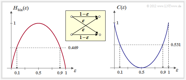
The right graph shows the BSC channel capacity depending on the falsificaion probability $\varepsilon$. On the left, for comparison, the binary entropy function is shown, which has already been defined in the chapter "memoryless sources" of the book "Information Theory".
One can see from this representation:
- The falsificaion probability $\varepsilon$ leads to the channel capacity $C(\varepsilon)$. According to the "channel coding theorem" error-free decoding is only possible if the code rate $R \le C(\varepsilon)$.
- With $\varepsilon = 10\%$, error-free decoding is impossible if the code rate $R > 0.531$ $($because: $C(0.1) = 0.531)$.
- With $\varepsilon = 50\%$, error-free decoding is impossible even if the code rate is arbitrarily small $($because: $C(0.5) = 0)$.
- From an information theory point of view $\varepsilon = 1$ $($inversion of all bits$)$ is equivalent to $\varepsilon = 0$ $($"error-free transmission"$)$.
- Error-free decoding is achieved here by swapping the zeros and ones, i.e. by a so-called mapping".
- Similarly $\varepsilon = 0.9$ is equivalent to $\varepsilon = 0.1$.
Channel capacity of the AWGN model
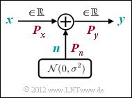
We now consider the "AWGN channel" ("Additive White Gaussian Noise").
Here, for the output signal $y = x + n$, where $n$ describes a "Gaussian distributed random variable" and it applies to their expected values ("moments"):
- ${\rm E}[n] = 0,$
- ${\rm E}[n^2] = P_n.$
Thus, regardless of the input signal $x$ $($analog or digital$)$, there is always a continuous-valued output signal $y$, and in the "equation for mutual information" is to be used:
- $$M_y \to\infty.$$
The calculation of the AWGN channel capacity is given here only in keywords. The exact derivation can be found in the fourth main chapter "Discrete Value Information Theory" of the textbook "Information theory".
- The input quantity $x$ optimized with respect to maximum mutual information will certainly be continuous-valued, that is, for the AWGN channel in addition to $M_y \to\infty$ also holds $M_x \to\infty$.
- While for discrete-valued input optimization is to be done over all probabilities ${\rm Pr}(x_i)$ now optimization is done using the "probability density funcion $\rm (PDF)$" $f_x(x)$ of the input signal under the constraint "power limitation":
- \[C = \max_{f_x(x)} \hspace{0.1cm} I(x; y)\hspace{0.05cm},\hspace{0.3cm}{\rm where \hspace{0.15cm} must \hspace{0.15cm} apply} \text{:}\hspace{0.15cm} {\rm E} \left [ x^2 \right ] \le P_x \hspace{0.05cm}.\]
- The optimization also yields a Gaussian distribution for the input PDF ⇒ $x$, $n$ and $y$ are Gaussian distributed according to the probability density functions $f_x(x)$, $f_n(n)$ and $f_y(y)$. We designate the corresponding powers $P_x$, $P_n$ and $P_y$.
- After longer calculation one gets for the channel capacity using the "binary logarithm" $\log_2(\cdot)$ – again with the pseudo-unit "bit/channel use":
- \[C = {\rm log_2 } \hspace{0.15cm} \sqrt{\frac{P_y}{P_n }} = {\rm log_2 } \hspace{0.15cm} \sqrt{\frac{P_x + P_n}{P_n }} = {1}/{2 } \cdot {\rm log_2 } \hspace{0.05cm}\left ( 1 + \frac{P_x}{P_n } \right )\hspace{0.05cm}.\]
- If $x$ describes a discrete-time signal with symbol rate $1/T_{\rm S}$, it must be bandlimited to $B = 1/(2T_{\rm S})$, and the same bandwidth $B$ must be applied to the noise signal $n$ ⇒ "noise bandwidth":
- \[P_X = \frac{E_{\rm S}}{T_{\rm S} } \hspace{0.05cm}, \hspace{0.4cm} P_N = \frac{N_0}{2T_{\rm S} }\hspace{0.05cm}. \]
- Thus, the AWGN channel capacity can also be expressed by the transmit energy per symbol $(E_{\rm S})$ and the noise power density $(N_0)$:
- \[C = {1}/{2 } \cdot {\rm log_2 } \hspace{0.05cm}\left ( 1 + {2 E_{\rm S}}/{N_0 } \right )\hspace{0.05cm}, \hspace{1.9cm} \text {unit:}\hspace{0.3cm} \frac{\rm bit}{\rm channel\:use}\hspace{0.05cm}.\]
- The following equation gives the channel capacity per unit time $($denoted by $^{\star})$:
- \[C^{\star} = \frac{C}{T_{\rm S} } = B \cdot {\rm log_2 } \hspace{0.05cm}\left ( 1 + {2 E_{\rm S}}/{N_0 } \right )\hspace{0.05cm}, \hspace{0.8cm}
\text {unit:} \hspace{0.3cm} \frac{\rm bit}{\rm time\:unit}\hspace{0.05cm}.\]
$\text{Example 1:}$
- For $E_{\rm S}/N_0 = 7.5$ ⇒ $10 \cdot \lg \, E_{\rm S}/N_0 = 8.75 \, \rm dB$ the channel capacity is
- $$C = {1}/{2 } \cdot {\rm log_2 } \hspace{0.05cm} (16) = 2 \, \rm bit/channel\:use.$$
- For a channel with the (physical) bandwidth $B = 4 \, \rm kHz$, which corresponds to the sampling rate $f_{\rm A} = 8\, \rm kHz$:
- $$C^\star = 16 \, \rm kbit/s.$$
- However, a comparison of different coding methods at constant "energy per transmitted symbol" ⇒ $E_{\rm S}$ is not fair.
- Rather, for this comparison, the "energy per source bit" ⇒ $E_{\rm B}$ should be fixed. The following relationships apply:
- \[E_{\rm S} = R \cdot E_{\rm B} \hspace{0.3cm} \Rightarrow \hspace{0.3cm} E_{\rm B} = E_{\rm S} / R \hspace{0.05cm}. \]
$\text{Channel Coding Theorem for the AWGN channel:}$
- Error-free decoding $($at infinitely long blocks ⇒ $n \to \infty)$ is always possible if the code rate $R$ is smaller than the channel capacity $C$:
- \[R < C = {1}/{2 } \cdot {\rm log_2 } \hspace{0.05cm}\left ( 1 +2 \cdot R\cdot E_{\rm B}/{N_0 } \right )\hspace{0.05cm}.\]
- For each code rate $R$ the required $E_{\rm B}/N_0$ of the AWGN channel can thus be determined so that error-free decoding is just possible.
- One obtains for the limiting case $R = C$:
- \[{E_{\rm B} }/{N_0} > \frac{2^{2R}-1}{2R } \hspace{0.05cm}.\]
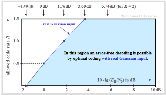
The graph summarizes the result, with the ordinate $R$ plotted on a linear scale and the abscissa $E_{\rm B}/{N_0 }$ plotted logarithmically.
- Error-free coding is not possible outside the blue area.
- The blue limit curve indicates the AWGN channel capacity $C$.
From this graph and the above equation, the following can be deduced:
- Channel capacity $C$ increases with $10 \cdot \lg \, E_{\rm B}/N_0 $ somewhat less than linearly. In the graph, some selected function values are indicated as blue crosses.
- If $10 \cdot \lg \, E_{\rm B}/N_0 < -1.59 \, \rm dB$, error-free decoding is impossible in principle. If the code rate $R = 0.5$, then $10 \cdot \lg \, E_{\rm B}/N_0 > 0 \, \rm dB$ must be ⇒ $E_{\rm B} > N_0$.
- For all binary codes holds per se $0 < R ≤ 1$. Only with non-binary codes ⇒ rates $R > 1$ are possible. For example, the maximum possible code rate of a quaternary code: $R = \log_2 \, M_y = \log_2 \, 4 = 2$.
- All one-dimensional modulation types – i.e., those methods that use only the in-phase– or only the quadrature component such as "2–ASK", "BPSK" and "2–FSK" must be in the blue area of the present graphic.
- As shown in the chapter "Maximum code rate for QAM structures", there is a "friendlier" limit curve for two-dimensional modulation types such as the "Quadrature Amplitude Modulation".
AWGN channel capacity for binary input signals
In this book we restrict ourselves mainly to binary codes, that is, to the Galois field ${\rm GF}(2^n)$. With this
- firstly, the code rate is limited to the range $R ≤ 1$,
- secondly, also for $R ≤ 1$ not the whole blue region is available (see previous page).
- The now valid region results from the "general equation" of mutual information by
- the parameters $M_x = 2$ and $M_y \to \infty$,
- bipolar signaling ⇒ $x=0$ → $\tilde{x} = +1$ and $x=1$ → $\tilde{x} = -1$,
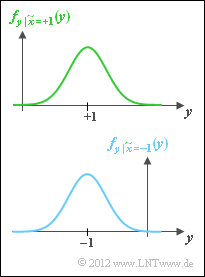
- the transition from conditional probabilities ${\rm Pr}(\tilde{x}_i)$ to conditional probability density functions,
- replace the sum with an integration.
- The optimization of the source leads to equally probable symbols:
- \[{\rm Pr}(\tilde{x} = +1) = {\rm Pr}(\tilde{x} = -1) = 1/2 \hspace{0.05cm}. \]
- This gives for the maximum of the mutual information, i.e. for the channel capacity:
- \[C \hspace{-0.15cm} = {1}/{2} \cdot \int_{-\infty }^{+ \infty} \left [ f_{y\hspace{0.05cm} |\hspace{0.05cm}\tilde{x} = +1}(y)\cdot {\rm log_2 } \hspace{0.15cm}\frac {f_{y\hspace{0.05cm} |\hspace{0.05cm}\tilde{x} = +1}(y)}{f_y(y)} + f_{y\hspace{0.05cm} |\hspace{0.05cm}\tilde{x} = -1}(y)\cdot {\rm log_2 } \hspace{0.15cm}\frac {f_{y\hspace{0.05cm} |\hspace{0.05cm}\tilde{x} = -1}(y)}{f_y(y)} \right ]\hspace{0.1cm}{\rm d}y \hspace{0.05cm}.\]
The integral cannot be solved in mathematical closed form, but can only be evaluated numerically.
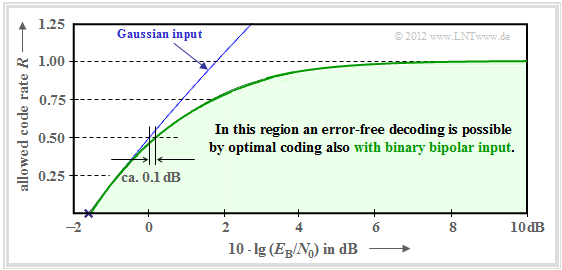
- The green curve shows the result.
- The blue curve gives for comparison the channel capacity for Gaussian distributed input signals derived on the last page.
It can be seen:
- For $10 \cdot \lg \, E_{\rm B}/N_0 < 0 \, \rm dB$ the two capacitance curves differ only slightly.
- So, for binary bipolar input, compared to the optimum (Gaussian) input, the characteristic $10 \cdot \lg \, E_{\rm B}/N_0$ only needs to be increased by about $0.1 \, \rm dB$ to also allow the code rate $R = 0.5$.
- From $10 \cdot \lg \, E_{\rm B}/N_0 \approx6 \, \rm dB$ the capacity $C = 1 \, \rm bit/channel\:use$ of the AWGN channel for binary input is almost reached.
- In between, the limit curve is approximately exponentially increasing.
Common channel codes versus channel capacity
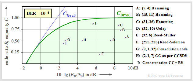
Now it shall be shown to what extent established channel codes approximate the BPSK channel capacity (green curve). In the following graph the rate $R=k/n$ of these codes or the capacity $C$ (with the additional pseudo–unit "bit/channel use") is plotted as ordinate.
Further, it is assumed:
- the AWGN–channel, denoted by $10 \cdot \lg \, E_{\rm B}/N_0$ in dB, and
- bit error rate $\rm BER=10^{-5}$ for all codes marked by crosses.
$\text{Please note:}$
- The channel capacity curves always apply to $n \to \infty$ and $\rm BER \to 0$ .
- If one would apply this strict requirement "error-free" also to the considered channel codes of finite code length $n$, this would always require $10 \cdot \lg \, E_{\rm B}/N_0 \to \infty$ .
- But this is an academic problem of little practical significance. For $\rm BER = 10^{-10}$ a qualitatively and also quantitatively similar graph would result.
- For convolutional codes, the third identifier parameter has a different meaning than for block codes. For example, $\text{CC (2, 1, 32)}$ indicates the memory $m = 32$
The following are some explanations of the data taken from the lecture [Liv10][1]:
- The points $\rm A$, $\rm B$ and $\rm C$ mark "Hamming codes" of different rate. They all require for $\rm BER = 10^{-5}$ more than $10 \cdot \lg \, E_{\rm B}/N_0 = 8 \, \rm dB$.
- $\rm D$ denotes the binary "Golay code" with rate $1/2$ and $\rm E$ denotes a "Reed–Muller code". This very low rate code was used 1971 on the Mariner 9 spacecraft.
- Marked by $\rm F$ is a high rate "Reed–Solomon codes" $(R = 223/255 > 0.9)$ and a required $10 \cdot \lg \, E_{\rm B}/N_0 < 6 \, \rm dB$.
- The markers $\rm G$ and $\rm H$ denote exemplary "convolutional codes" medium rate. The code $\rm G$ was used as early as 1972 on the Pioneer10 mission.
- The channel coding of the Voyager–mission in the late 1970s is marked by $\rm I$. It is the concatenation of a $\text{CC (2, 1, 7)}$ with a "Reed–Solomon code".
Much better results can be achieved with iterative decoding methods (see fourth main chapter), as the second graph shows.
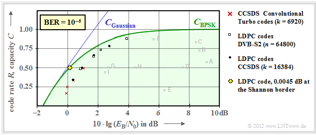
- This means: The individual marker points are much closer to the capacity curve $C_{\rm BPSK}$ for digital input.
- The solid blue Gaussian capacity curve is labeled $C_{\rm Gaussian}$.
Here are some more explanations about this graph:
- Red crosses mark so-called "turbo codes" accordingt to "CCSDS" ("Consultative Committee for Space Data Systems") with each $k = 6920$ information bits and different code lengths $n$.
- These codes, invented by Claude Berrou around 1990, can be decoded iteratively. The (red) marks are each less than $1 \, \rm dB$ from the Shannon bound.
- Similar behavior is shown by "LDPC codes" ("Low Density Parity–check Codes") marked by white rectangles, which have been used since in 2006 on "DVB–S(2)" ("Digital Video Broadcast over Satellite").
- These are well suited for iterative decoding using "factor–graphs" and "exit charts" due to the sparse occupancy of the parity-check matrix $\boldsymbol {\rm H}$ (with "ones"). See [Hag02][2]
- The black dots mark the CCSDS specified "LDPC codes", all of which assume a constant number of information bits $(k = 16384)$.
- In contrast, for all white rectangles, the code length $n = 64800$ is constant, while the number $k$ of information bits changes according to the rate $R = k/n$.
- Around the year 2000, many researchers had the ambition to approach the Shannon bound to within fractions of a $\rm dB$. The yellow cross marks such a result from [CFRU01][3]. Used an irregular rate–1/2–LDPC of code length $n = 2 \cdot10^6$.
$\text{Conclusion:}$ It should be noted that Shannon recognized and proved as early as 1948 that no one-dimensional modulation method can lie to the left of the AWGN limit curve "Gaussian (real)" drawn throughout.
- For two-dimensional methods such as QAM and multilevel PSK, on the other hand, the "Gaussian (complex)" limit curve applies, which is drawn here as a dashed line and always lies to the left of the solid curve.
- For more details, see the "Maximum code rate for QAM structures" section of the "Information Theory" book.
- Also, this limit curve has now been nearly reached with QAM procedures and very long channel codes, without ever being exceeded.
Exercises for the chapter
Exercise 1.17: About the Channel Coding Theorem
Exercise 1.17Z: BPSK Channel Capacity
References
- ↑ Liva, G.: Channel Coding. Lecture manuscript, Chair of Communications Engineering, TU Munich and DLR Oberpfaffenhofen, 2010.
- ↑ Hagenauer, J.: The Turbo Principle in Mobile Communications. In: Int. Symp. on Information Theory and Its Applications, Oct.2010, PDF–Dokument.
- ↑ Chung S.Y; Forney Jr., G.D.; Richardson, T.J.; Urbanke, R.: On the Design of Low-Density Parity- Check Codes within 0.0045 dB of the Shannon Limit. – In: IEEE Communications Letters, vol. 5, no. 2 (2001), pp. 58–60.
