Difference between revisions of "Digital Signal Transmission/Consideration of Channel Distortion and Equalization"
| Line 31: | Line 31: | ||
{{GraueBox|TEXT= | {{GraueBox|TEXT= | ||
| − | $\text{Example 1:}$ We consider again a binary system with NRZ rectangular pulses and a Gaussian receiver filter $H_{\rm E}(f) = H_{\rm G}(f)$ with (normalized) cutoff frequency $f_\text{G, opt} \cdot T = 0.4$. | + | $\text{Example 1:}$ We consider again a binary system with NRZ rectangular pulses and a Gaussian receiver filter $H_{\rm E}(f) = H_{\rm G}(f)$ with (normalized) cutoff frequency $f_\text{G, opt} \cdot T = 0.4$. Due to this unfavorable receiver filter $H_{\rm E}(f)$ intersymbol interference $\rm (ISI)$ occurs in all variants presented here. |
*The middle graph shows the eye diagram of the signal component $d_{\rm S}(t)$ of the detection signal for this case – i.e. without taking the noise into account. | *The middle graph shows the eye diagram of the signal component $d_{\rm S}(t)$ of the detection signal for this case – i.e. without taking the noise into account. | ||
| Line 41: | Line 41: | ||
⇒ The left (noisy) diagram is obtained for the ideal channel, i.e., for | ⇒ The left (noisy) diagram is obtained for the ideal channel, i.e., for | ||
:$$H_{\rm K}(f) = 1 \ \ ⇒ \ \ 1/H_{\rm K}(f) = 1.$$ | :$$H_{\rm K}(f) = 1 \ \ ⇒ \ \ 1/H_{\rm K}(f) = 1.$$ | ||
| − | It takes into account the AWGN noise, but here it was assumed to be very small, $10 \cdot {\rm lg}\hspace{0.1cm} E_{\rm B}/N_0 = 30 \ \rm dB$. For this configuration, the | + | It takes into account the AWGN noise, but here it was assumed to be very small, $10 \cdot {\rm lg}\hspace{0.1cm} E_{\rm B}/N_0 = 30 \ \rm dB$. For this configuration, the worst-case SNR it was determined by simulation: |
:$$10 \cdot {\rm | :$$10 \cdot {\rm | ||
lg}\hspace{0.1cm}\rho_{\rm U}\approx 26.8\,{\rm dB} | lg}\hspace{0.1cm}\rho_{\rm U}\approx 26.8\,{\rm dB} | ||
| Line 47: | Line 47: | ||
10^{-40}\hspace{0.05cm}.$$ | 10^{-40}\hspace{0.05cm}.$$ | ||
| − | ⇒ The right (also noisy) diagram applies to a [[Digital_Signal_Transmission/Causes_and_Effects_of_Intersymbol_Interference#Frequency_response_of_a_coaxial_cable| | + | ⇒ The right (also noisy) diagram applies to a [[Digital_Signal_Transmission/Causes_and_Effects_of_Intersymbol_Interference#Frequency_response_of_a_coaxial_cable|coaxial cable]], where the characteristic cable attenuation $a_\star = 40 \ \rm dB$. This results in significantly worse system performance for the same $E_{\rm B}/N_0$: |
:$$10 \cdot {\rm | :$$10 \cdot {\rm | ||
lg}\hspace{0.1cm}\rho_{\rm U}\approx -4.6\,{\rm dB} | lg}\hspace{0.1cm}\rho_{\rm U}\approx -4.6\,{\rm dB} | ||
| Line 53: | Line 53: | ||
0.28\hspace{0.05cm}.$$ | 0.28\hspace{0.05cm}.$$ | ||
| + | This result can be interpreted as follows: | ||
| + | *Assuming an ideal channel equalizer $1/H_{\rm K}(f)$, the same "eye diagram without noise" (left diagram) results for the distorting channel as for the ideal, distortion-free channel $H_{\rm K}(f) = 1$ (middle graph).<br> | ||
| − | + | *Channel equalization $1/H_{\rm K}(f)$ extremely amplifies the noise component $d_{\rm N}(t)$ of the detection signal. In the right-hand example, equally strong equalization is required over a wide frequency range because of the strong distortion. | |
| − | * | ||
| − | + | *The noise power $\sigma_d^2$ here is larger by a factor of $1300$ than in the left constellation $($no distortion ⇒ no equalization$)$. Thus, the error probability results in $p_{\rm S}\approx p_{\rm U}\approx 50 \%$.<br> | |
| − | *The noise power $\sigma_d^2$ here is larger by a factor of $1300$ than in the left constellation (no distortion ⇒ no equalization). Thus, the error probability results in $p_{\rm S}\approx p_{\rm U}\approx 50 \%$.<br> | ||
| − | *An acceptable error probability results only with smaller noise power density $N_0$. For example, with $10 \cdot {\rm lg}\hspace{0.1cm} E_{\rm B}/N_0 = 50 \ \rm dB$ $($instead of $30 \ \rm dB)$ the following result is obtained: | + | *An acceptable worst-case error probability results only with smaller noise power density $N_0$. For example, with $10 \cdot {\rm lg}\hspace{0.1cm} E_{\rm B}/N_0 = 50 \ \rm dB$ $($instead of $30 \ \rm dB)$ the following result is obtained: |
:$$10 \cdot {\rm | :$$10 \cdot {\rm | ||
lg}\hspace{0.1cm}\rho_{\rm U} = -4.6 +20 \approx 15.4\,{\rm dB} | lg}\hspace{0.1cm}\rho_{\rm U} = -4.6 +20 \approx 15.4\,{\rm dB} | ||
| Line 68: | Line 68: | ||
== Increase of the noise power by linear equalization== | == Increase of the noise power by linear equalization== | ||
<br> | <br> | ||
| − | The eye diagrams on the last section impressively document the increase of the noise power $\sigma_d^2$ with unchanged vertical eye opening, if one compensates the channel frequency response $H_{\rm K}(f)$ on the receiving side by its inverse. This result shall now be interpreted in terms of the noise power density ${\it \Phi}_{d{\rm N}}(f)$ after the receiver filter (before the decision), with the following settings: | + | The eye diagrams on the last section impressively document the increase of the noise power $\sigma_d^2$ with unchanged vertical eye opening, if one compensates the channel frequency response $H_{\rm K}(f)$ on the receiving side by its inverse. This result shall now be interpreted in terms of the noise power density ${\it \Phi}_{d{\rm N}}(f)$ after the receiver filter (before the decision), with the following settings: |
| − | *Let the channel be a [[Digital_Signal_Transmission/Causes_and_Effects_of_Intersymbol_Interference#Frequency_response_of_a_coaxial_cable| | + | *Let the channel be a [[Digital_Signal_Transmission/Causes_and_Effects_of_Intersymbol_Interference#Frequency_response_of_a_coaxial_cable|coaxial cable]] with the magnitude frequency response |
:$$|H_{\rm K}(f)| = {\rm exp}\left [- a_{\star}\cdot \sqrt{2 f | :$$|H_{\rm K}(f)| = {\rm exp}\left [- a_{\star}\cdot \sqrt{2 f | ||
T}\hspace{0.05cm} \right ]\hspace{0.2cm}{\rm with}\hspace{0.2cm} a_{\star} | T}\hspace{0.05cm} \right ]\hspace{0.2cm}{\rm with}\hspace{0.2cm} a_{\star} | ||
| − | = 1.7\,\,{\rm Np}\hspace{0.2cm} ({\rm corresponding to} \hspace{0.2cm} | + | = 1.7\,\,{\rm Np}\hspace{0.2cm} ({\rm corresponding \hspace{0.2cm} to} \hspace{0.2cm} |
15\,\,{\rm dB}) \hspace{0.05cm}.$$ | 15\,\,{\rm dB}) \hspace{0.05cm}.$$ | ||
| + | [[File:P ID1399 Dig T 3 3 S2 version1.png|right|frame|Noise power-spectral density before the decision due to distorting channel;<br>note that here, for reasons of presentation, the characteristic cable attenuation of $a_\star = 15 \ \rm dB$ $($corresponding to $1.7 \ \rm Np)$ is chosen to be significantly smaller than in the right eye diagram in [[Digital_Signal_Transmission/Consideration_of_Channel_Distortion_and_Equalization#Ideal_channel_equalizer|Example 1]] in the last section $($valid for $a_\star = 40 \ \rm dB)$.|class=fit]] | ||
| + | *The [[Digital_Signal_Transmission/Consideration_of_Channel_Distortion_and_Equalization#Ideal_channel_equalizer|ideal channel equalizer]] $1/H_{\rm K}(f)$ compensates the channel frequency response completely. No statement is made here about the realization of the attenuation and phase equalization.<br> | ||
| − | * | + | *For noise power limitation a [[Linear_and_Time_Invariant_Systems/Some_Low-Pass_Functions_in_Systems_Theory#Gaussian_low-pass_filter|Gaussian low-pass filter]] is used: |
| + | :$$|H_{\rm G}(f)| = {\rm exp}\left [- \pi \cdot \left (\frac{f }{2 f_{\rm G}}\right )^2 \right ] \hspace{0.05cm}.$$ | ||
| − | + | Thus, the noise power-spectral density before the decision is: | |
| − | |||
| − | |||
| − | |||
| − | |||
| − | |||
:$${\it \Phi}_{d{\rm N}}(f) = \frac{N_0}{2} \cdot \frac{|H_{\rm G | :$${\it \Phi}_{d{\rm N}}(f) = \frac{N_0}{2} \cdot \frac{|H_{\rm G | ||
| − | }(f)|^2}{|H_{\rm K}(f)|^2} = \frac{N_0}{2} \cdot {\rm exp}\left [2 \cdot | + | }(f)|^2}{|H_{\rm K}(f)|^2} $$ |
| + | :$$\Rightarrow \hspace{0.3cm} {\it \Phi}_{d{\rm N}}(f) = \frac{N_0}{2} \cdot {\rm exp}\left [2 \cdot | ||
a_{\star}\cdot \sqrt{2 f T} - {\pi}/{2} \cdot \left ({f }/{f_{\rm G}}\right )^2 \right ] \hspace{0.05cm}.$$ | a_{\star}\cdot \sqrt{2 f T} - {\pi}/{2} \cdot \left ({f }/{f_{\rm G}}\right )^2 \right ] \hspace{0.05cm}.$$ | ||
| − | + | This curve is shown for two (normalized) cutoff frequencies | |
| + | *$f_\text{G} \cdot T = 0.8$ (on the left), | ||
| + | *$f_\text{G} \cdot T = 0.4$ (on the right). | ||
| − | |||
| − | |||
| − | |||
| + | Let us first consider the left graph for the (normalized) cutoff frequency $f_\text{G} \cdot T = 0.8$, which – according to the calculations in the [[Digital_Signal_Transmission/Error_Probability_with_Intersymbol_Interference#Optimization_of_the_cutoff_frequency|last chapter]] – represents the optimum for the ideal channel ⇒ $H_{\rm K}(f) = 1$. | ||
| + | #The constant noise power density $N_0/2$ at the receiver input is highlighted in yellow. With an ideal channel, this is limited by the Gaussian receiver filter $H_{\rm E}(f) = H_{\rm G}(f)$ and results in the detection noise power $\sigma_d^2$ (indicated by the blue area in the graph).<br><br> | ||
| + | #If – as usual for "Wireline Transmission Technology" – higher frequencies are strongly attenuated, $|H_{\rm E}(f)| = |H_{\rm G}(f)|/|H_{\rm K}(f)|$ increases very strongly due to the ideal channel equalizer before the attenuating influence of the Gaussian filter becomes effective for $f \cdot T \ge 0.6$ $($only valid for $a_\star = 15 \ \rm dB$ and $f_\text{G} \cdot T = 0.8)$. <br><br> | ||
| + | #The noise power $\sigma_d^2$ is now equal to the area under the red curve, which is about a factor of $28$ larger than the blue area. The effects of these different noise powers can be seen qualitatively in the left and right eye diagrams on the last section, but for $a_\star = 40 \ \rm dB$.<br><br> | ||
| − | + | The right graph shows the noise power density ${\it \Phi}_{d{\rm N}}(f)$ for the normalized cutoff frequency $f_\text{G} \cdot T = 0.4$. Here the noise power is only increased by a factor of $9$ by the ideal channel equalizer (ratio between the area under the red curve and the blue area).<br> | |
| − | |||
| − | |||
| − | |||
| − | |||
| − | |||
| − | |||
| − | |||
| − | |||
| − | The right graph shows the noise power density ${\it \Phi}_{d{\rm N}}(f)$ for the normalized cutoff frequency $f_\text{G} \cdot T = 0.4$. Here the noise power is only increased by a factor of $9$ by the ideal channel equalizer (ratio between the area under the red curve and the blue area).<br> | ||
{{BlaueBox|TEXT= | {{BlaueBox|TEXT= | ||
| Line 111: | Line 104: | ||
== Optimization of the cutoff frequency== | == Optimization of the cutoff frequency== | ||
<br> | <br> | ||
| − | The graph shows the signal-to-noise ratios as a function of the cutoff frequency $f_{\rm G}$ of the overall Gaussian frequency response $H_{\rm G}(f) = H_{\rm K}(f) \cdot H_{\rm E}(f)$. | + | The graph shows the signal-to-noise ratios as a function of the cutoff frequency $f_{\rm G}$ of the overall Gaussian frequency response $H_{\rm G}(f) = H_{\rm K}(f) \cdot H_{\rm E}(f)$. |
| − | + | [[File:EN Dig T 3 3 S1b.png|right|frame|Optimal cut-off frequency of the Gaussian low-pass with distorting channel $(a_\star = 15 \ \rm dB).$<br>⇒ The circles show the dB values for $10 \cdot {\rm lg}\hspace{0.1cm} \rho_d$ ⇒ "mean detection SNR" ⇒ measure of mean error probability $p_{\rm S}$.<br>⇒ The squares show the dB values for $10 \cdot {\rm lg}\hspace{0.1cm} \rho_{\rm U}$ ⇒ "worst-case SNR" ⇒ measure of worst-case error probability $p_{\rm U}$.|class=fit]] | |
| − | + | ||
| − | [[File:EN Dig T 3 3 S1b.png|right|frame|Optimal cut-off frequency of the | + | This graphic is valid for |
| − | + | *a [[Digital_Signal_Transmission/Causes_and_Effects_of_Intersymbol_Interference#Frequency_response_of_a_coaxial_cable|coaxial transmission channel]] with characteristic cable attenuation $a_\star = 15 \ \rm dB$,<br> | |
| − | + | ||
| − | + | *AWGN noise with $10 \cdot {\rm lg}\hspace{0.1cm} E_{\rm B}/N_0 = 27 \ \rm dB$, with $E_{\rm B} = s_0^2 \cdot T$ ⇒ NRZ rectangular pulses.<br> | |
| − | |||
| − | |||
| − | |||
| − | |||
| − | |||
| − | + | One can see by comparison with the [[Digital_Signal_Transmission/Error_Probability_with_Intersymbol_Interference#Optimization_of_the_cutoff_frequency|corresponding plot]] in the last chapter, which was valid for $H_{\rm K}(f) = 1$, $10 \cdot {\rm lg}\hspace{0.1cm} E_{\rm B}/N_0 = 13 \ \rm dB$: | |
| − | + | #Even with a highly distorting channel, $\rho_{\rm U}$ is a suitable lower bound for $\rho_d$ ⇒ $\rho_{d} \ge \rho_{\rm U}$. Correspondingly, $p_{\rm U} \ge p_{\rm S} $ is also a reasonable upper bound for $p_{\rm S}$.<br><br> | |
| − | \hspace{0.3cm} 10 \cdot {\rm lg}\hspace{0.1cm}\rho_{\rm U}\approx | + | #For the considered cable attenuation $a_\star = 15 \ \rm dB$, the cutoff frequency $f_\text{G} \cdot T \approx 0.55$ is optimal and $\ddot{o}/s_0 \approx 1.327$ and $\sigma_d/s_0 \approx 0.106$ hold.<br><br> |
| + | #This gives the worst-case SNR $10 \cdot {\rm lg}\hspace{0.1cm} \rho_{\rm U} \approx \ \rm 15.9 \ dB$ and the worst–case error probability $p_{\rm U} \approx 2 \cdot 10^{-9}.$<br><br> | ||
| + | #A smaller cutoff frequency would result in a significantly smaller eye opening without equally reducing $\sigma_d$. For $f_\text{G} \cdot T = 0.4$:<br> $\ddot{o}/s_0 \approx 0.735,\hspace{0.2cm}\sigma_d/s_0 \approx 0.072$<br> $\Rightarrow \hspace{0.3cm} 10 \cdot {\rm lg}\hspace{0.1cm}\rho_{\rm U}\approx | ||
14.1\,{\rm dB} | 14.1\,{\rm dB} | ||
\hspace{0.3cm}\Rightarrow | \hspace{0.3cm}\Rightarrow | ||
| − | \hspace{0.3cm} p_{\rm U}\approx 1.8 \cdot 10^{-7}\hspace{0.05cm}. | + | \hspace{0.3cm} p_{\rm U}\approx 1.8 \cdot 10^{-7}\hspace{0.05cm}.$ |
| − | + | #If the cutoff frequency $f_\text{G}$ is too large, the noise is limited less effectively. For example, the values for the cutoff frequency are $f_\text{G} \cdot T =0.8$: | |
| − | |||
:$$\ddot{o}/s_0 \approx 1.819,\hspace{0.2cm}\sigma_d/s_0 \approx 0.178\hspace{0.3cm}\Rightarrow | :$$\ddot{o}/s_0 \approx 1.819,\hspace{0.2cm}\sigma_d/s_0 \approx 0.178\hspace{0.3cm}\Rightarrow | ||
\hspace{0.3cm} 10 \cdot {\rm lg}\hspace{0.1cm}\rho_{\rm U}\approx | \hspace{0.3cm} 10 \cdot {\rm lg}\hspace{0.1cm}\rho_{\rm U}\approx | ||
Revision as of 18:52, 15 June 2022
Contents
Ideal channel equalizer
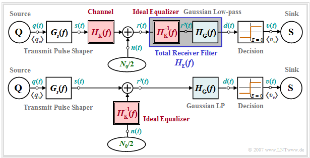
For a transmission system whose channel frequency response $H_{\rm K}(f)$ causes severe distortion, we assume the following block diagram (upper graph) and equivalent circuit (lower graph). To these representations the following is to be noted:
- The receiver filter $H_{\rm E}(f)$ is – at least mentally – composed of an ideal equalizer $1/H_{\rm K}(f)$ and a low-pass filter $H_{\rm G}(f)$. For the latter we use in this chapter exemplarily a Gaussian low-pass with the cutoff frequency $f_{\rm G}$.
- If we now move the ideal equalizer – again purely mentally – to the left side of the noise addition point, nothing changes with respect to the S/N ratio before the decision device and with respect to the error probability compared to the block diagram drawn above.
- From the equivalent diagram below it can be seen that the channel frequency response $H_{\rm K}(f)$ does not change anything with respect to the signal component $d_{\rm S}(t)$ of the detection signal if it is fully compensated with $1/H_{\rm K}(f)$.
- Thus, the signal component $d_{\rm S}(t)$ – originating from the transmitted signal $s(t)$ – has exactly the same shape as calculated in the chapter "Error Probability with Intersymbol Interference".
- The degradation due to the frequency response $H_{\rm K}(f)$ is rather shown by a significant increase of the detection noise power, i.e. the variance of the noise component $d_{\rm N}(t)$ – originating from the noise signal $n(t)$ at the receiver input:
- $$\sigma_d^2 = \frac{N_0}{2} \cdot \int_{-\infty}^{+\infty} |H_{\rm E}(f)|^2 \,{\rm d} f = \frac{N_0}{2} \cdot \int_{-\infty}^{+\infty} \frac{1}{|H_{\rm K}(f)|^2}\cdot |H_{\rm G}(f)|^2 \,{\rm d} f \hspace{0.05cm}.$$
- The prerequisite for a finite noise power $\sigma_d^2$ is that the Gaussian low-pass $H_{\rm G}(f)$ attenuates the noise $n(t)$ at (very) high frequencies more than it is raised by the ideal equalizer $1/H_{\rm K}(f)$.
Note: The channel frequency response $H_{\rm K}(f)$ must be equalized for magnitude and phase, but only in a limited frequency range specified by $H_{\rm G}(f)$ . However, a complete phase equalization is only possible at the expense of a (frequency-independent) delay time, which will not be considered further in the following.
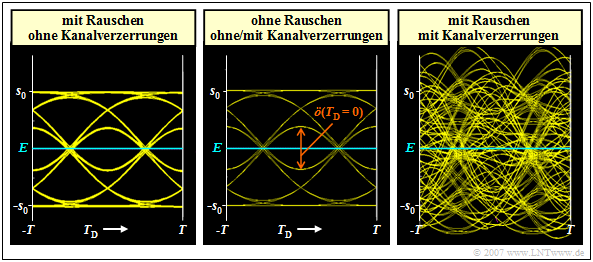
$\text{Example 1:}$ We consider again a binary system with NRZ rectangular pulses and a Gaussian receiver filter $H_{\rm E}(f) = H_{\rm G}(f)$ with (normalized) cutoff frequency $f_\text{G, opt} \cdot T = 0.4$. Due to this unfavorable receiver filter $H_{\rm E}(f)$ intersymbol interference $\rm (ISI)$ occurs in all variants presented here.
- The middle graph shows the eye diagram of the signal component $d_{\rm S}(t)$ of the detection signal for this case – i.e. without taking the noise into account.
- This is identical with the eye diagram shown in the section "Definition and statements of the eye diagram" in $\text{Example 3}$ of the last chapter (right diagram).
⇒ The left (noisy) diagram is obtained for the ideal channel, i.e., for
- $$H_{\rm K}(f) = 1 \ \ ⇒ \ \ 1/H_{\rm K}(f) = 1.$$
It takes into account the AWGN noise, but here it was assumed to be very small, $10 \cdot {\rm lg}\hspace{0.1cm} E_{\rm B}/N_0 = 30 \ \rm dB$. For this configuration, the worst-case SNR it was determined by simulation:
- $$10 \cdot {\rm lg}\hspace{0.1cm}\rho_{\rm U}\approx 26.8\,{\rm dB} \hspace{0.3cm}\Rightarrow \hspace{0.3cm} p_{\rm U}< 10^{-40}\hspace{0.05cm}.$$
⇒ The right (also noisy) diagram applies to a coaxial cable, where the characteristic cable attenuation $a_\star = 40 \ \rm dB$. This results in significantly worse system performance for the same $E_{\rm B}/N_0$:
- $$10 \cdot {\rm lg}\hspace{0.1cm}\rho_{\rm U}\approx -4.6\,{\rm dB} \hspace{0.3cm}\Rightarrow \hspace{0.3cm} p_{\rm U}\approx 0.28\hspace{0.05cm}.$$
This result can be interpreted as follows:
- Assuming an ideal channel equalizer $1/H_{\rm K}(f)$, the same "eye diagram without noise" (left diagram) results for the distorting channel as for the ideal, distortion-free channel $H_{\rm K}(f) = 1$ (middle graph).
- Channel equalization $1/H_{\rm K}(f)$ extremely amplifies the noise component $d_{\rm N}(t)$ of the detection signal. In the right-hand example, equally strong equalization is required over a wide frequency range because of the strong distortion.
- The noise power $\sigma_d^2$ here is larger by a factor of $1300$ than in the left constellation $($no distortion ⇒ no equalization$)$. Thus, the error probability results in $p_{\rm S}\approx p_{\rm U}\approx 50 \%$.
- An acceptable worst-case error probability results only with smaller noise power density $N_0$. For example, with $10 \cdot {\rm lg}\hspace{0.1cm} E_{\rm B}/N_0 = 50 \ \rm dB$ $($instead of $30 \ \rm dB)$ the following result is obtained:
- $$10 \cdot {\rm lg}\hspace{0.1cm}\rho_{\rm U} = -4.6 +20 \approx 15.4\,{\rm dB} \hspace{0.3cm}\Rightarrow \hspace{0.3cm} p_{\rm U}\approx 2 \cdot 10^{-9} \hspace{0.3cm}\Rightarrow \hspace{0.3cm} p_{\rm S} \ge p_{\rm U}/4 \approx 0.5 \cdot 10^{-9}\hspace{0.05cm}.$$
Increase of the noise power by linear equalization
The eye diagrams on the last section impressively document the increase of the noise power $\sigma_d^2$ with unchanged vertical eye opening, if one compensates the channel frequency response $H_{\rm K}(f)$ on the receiving side by its inverse. This result shall now be interpreted in terms of the noise power density ${\it \Phi}_{d{\rm N}}(f)$ after the receiver filter (before the decision), with the following settings:
- Let the channel be a coaxial cable with the magnitude frequency response
- $$|H_{\rm K}(f)| = {\rm exp}\left [- a_{\star}\cdot \sqrt{2 f T}\hspace{0.05cm} \right ]\hspace{0.2cm}{\rm with}\hspace{0.2cm} a_{\star} = 1.7\,\,{\rm Np}\hspace{0.2cm} ({\rm corresponding \hspace{0.2cm} to} \hspace{0.2cm} 15\,\,{\rm dB}) \hspace{0.05cm}.$$
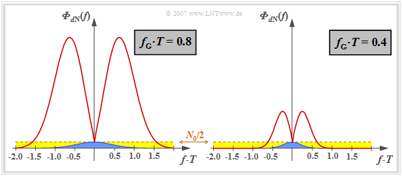
note that here, for reasons of presentation, the characteristic cable attenuation of $a_\star = 15 \ \rm dB$ $($corresponding to $1.7 \ \rm Np)$ is chosen to be significantly smaller than in the right eye diagram in Example 1 in the last section $($valid for $a_\star = 40 \ \rm dB)$.
- The ideal channel equalizer $1/H_{\rm K}(f)$ compensates the channel frequency response completely. No statement is made here about the realization of the attenuation and phase equalization.
- For noise power limitation a Gaussian low-pass filter is used:
- $$|H_{\rm G}(f)| = {\rm exp}\left [- \pi \cdot \left (\frac{f }{2 f_{\rm G}}\right )^2 \right ] \hspace{0.05cm}.$$
Thus, the noise power-spectral density before the decision is:
- $${\it \Phi}_{d{\rm N}}(f) = \frac{N_0}{2} \cdot \frac{|H_{\rm G }(f)|^2}{|H_{\rm K}(f)|^2} $$
- $$\Rightarrow \hspace{0.3cm} {\it \Phi}_{d{\rm N}}(f) = \frac{N_0}{2} \cdot {\rm exp}\left [2 \cdot a_{\star}\cdot \sqrt{2 f T} - {\pi}/{2} \cdot \left ({f }/{f_{\rm G}}\right )^2 \right ] \hspace{0.05cm}.$$
This curve is shown for two (normalized) cutoff frequencies
- $f_\text{G} \cdot T = 0.8$ (on the left),
- $f_\text{G} \cdot T = 0.4$ (on the right).
Let us first consider the left graph for the (normalized) cutoff frequency $f_\text{G} \cdot T = 0.8$, which – according to the calculations in the last chapter – represents the optimum for the ideal channel ⇒ $H_{\rm K}(f) = 1$.
- The constant noise power density $N_0/2$ at the receiver input is highlighted in yellow. With an ideal channel, this is limited by the Gaussian receiver filter $H_{\rm E}(f) = H_{\rm G}(f)$ and results in the detection noise power $\sigma_d^2$ (indicated by the blue area in the graph).
- If – as usual for "Wireline Transmission Technology" – higher frequencies are strongly attenuated, $|H_{\rm E}(f)| = |H_{\rm G}(f)|/|H_{\rm K}(f)|$ increases very strongly due to the ideal channel equalizer before the attenuating influence of the Gaussian filter becomes effective for $f \cdot T \ge 0.6$ $($only valid for $a_\star = 15 \ \rm dB$ and $f_\text{G} \cdot T = 0.8)$.
- The noise power $\sigma_d^2$ is now equal to the area under the red curve, which is about a factor of $28$ larger than the blue area. The effects of these different noise powers can be seen qualitatively in the left and right eye diagrams on the last section, but for $a_\star = 40 \ \rm dB$.
The right graph shows the noise power density ${\it \Phi}_{d{\rm N}}(f)$ for the normalized cutoff frequency $f_\text{G} \cdot T = 0.4$. Here the noise power is only increased by a factor of $9$ by the ideal channel equalizer (ratio between the area under the red curve and the blue area).
$\text{Conclusion:}$ From the above graph and the previous explanations it is already clear that with distorting channel ⇒ $H_{\rm K}(f) \ne 1$ the cutoff frequency $f_\text{G} \cdot T = 0.8$ of the Gaussian low-pass filter $H_{\rm G}(f)$ will no longer be optimal after the ideal channel equalizer $1/H_{\rm K}(f)$.
Optimization of the cutoff frequency
The graph shows the signal-to-noise ratios as a function of the cutoff frequency $f_{\rm G}$ of the overall Gaussian frequency response $H_{\rm G}(f) = H_{\rm K}(f) \cdot H_{\rm E}(f)$.
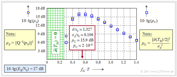
⇒ The circles show the dB values for $10 \cdot {\rm lg}\hspace{0.1cm} \rho_d$ ⇒ "mean detection SNR" ⇒ measure of mean error probability $p_{\rm S}$.
⇒ The squares show the dB values for $10 \cdot {\rm lg}\hspace{0.1cm} \rho_{\rm U}$ ⇒ "worst-case SNR" ⇒ measure of worst-case error probability $p_{\rm U}$.
This graphic is valid for
- a coaxial transmission channel with characteristic cable attenuation $a_\star = 15 \ \rm dB$,
- AWGN noise with $10 \cdot {\rm lg}\hspace{0.1cm} E_{\rm B}/N_0 = 27 \ \rm dB$, with $E_{\rm B} = s_0^2 \cdot T$ ⇒ NRZ rectangular pulses.
One can see by comparison with the corresponding plot in the last chapter, which was valid for $H_{\rm K}(f) = 1$, $10 \cdot {\rm lg}\hspace{0.1cm} E_{\rm B}/N_0 = 13 \ \rm dB$:
- Even with a highly distorting channel, $\rho_{\rm U}$ is a suitable lower bound for $\rho_d$ ⇒ $\rho_{d} \ge \rho_{\rm U}$. Correspondingly, $p_{\rm U} \ge p_{\rm S} $ is also a reasonable upper bound for $p_{\rm S}$.
- For the considered cable attenuation $a_\star = 15 \ \rm dB$, the cutoff frequency $f_\text{G} \cdot T \approx 0.55$ is optimal and $\ddot{o}/s_0 \approx 1.327$ and $\sigma_d/s_0 \approx 0.106$ hold.
- This gives the worst-case SNR $10 \cdot {\rm lg}\hspace{0.1cm} \rho_{\rm U} \approx \ \rm 15.9 \ dB$ and the worst–case error probability $p_{\rm U} \approx 2 \cdot 10^{-9}.$
- A smaller cutoff frequency would result in a significantly smaller eye opening without equally reducing $\sigma_d$. For $f_\text{G} \cdot T = 0.4$:
$\ddot{o}/s_0 \approx 0.735,\hspace{0.2cm}\sigma_d/s_0 \approx 0.072$
$\Rightarrow \hspace{0.3cm} 10 \cdot {\rm lg}\hspace{0.1cm}\rho_{\rm U}\approx 14.1\,{\rm dB} \hspace{0.3cm}\Rightarrow \hspace{0.3cm} p_{\rm U}\approx 1.8 \cdot 10^{-7}\hspace{0.05cm}.$ - If the cutoff frequency $f_\text{G}$ is too large, the noise is limited less effectively. For example, the values for the cutoff frequency are $f_\text{G} \cdot T =0.8$:
- $$\ddot{o}/s_0 \approx 1.819,\hspace{0.2cm}\sigma_d/s_0 \approx 0.178\hspace{0.3cm}\Rightarrow \hspace{0.3cm} 10 \cdot {\rm lg}\hspace{0.1cm}\rho_{\rm U}\approx 14.2\,{\rm dB} \hspace{0.3cm}\Rightarrow \hspace{0.3cm} p_{\rm U}\approx 1.7 \cdot 10^{-7}\hspace{0.05cm}.$$
- The optimal values of $10 \cdot {\rm lg}\hspace{0.1cm} \rho_{d} \approx 16.2 \ \rm dB$ and $10 \cdot {\rm lg}\hspace{0.1cm} \rho_{\rm U} \approx \ \rm 15.9 dB$ are much more pronounced than for ideal channel.
When comparing the signal-to-noise ratios, however, it must be taken into account that $10 \cdot {\rm lg}\hspace{0.1cm} E_{\rm B}/N_0 = 27 \ \rm dB$ is the basis here; in contrast, $10 \cdot {\rm lg}\hspace{0.1cm} E_{\rm B}/N_0 = 13 \ \rm dB$ was assumed in the "corresponding graph" for the ideal channel.
Optimal cut-off frequency as a function of cable attenuation
We further consider
- a binary system with NRZ transmission pulses ⇒ $E_{\rm B} = s_0^2 \cdot T$,
- a coaxial cable $H_{\rm K}(f)$, characteristic attenuation $a_\star$,
- a Gaussian total frequency response $H_{\rm G}(f) = H_{\rm K}(f) \cdot H_{\rm E}(f)$.
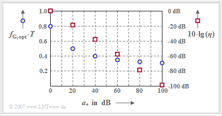
The blue circles (left axis labels) mark the optimal cutoff frequencies $f_\text{G, opt}$ for the respective cable attenuation $a_\star$.
In addition, the graph shows with red squares the "system efficiency" (at peak limitation) $\eta$, which is the ratio of the SNR $\rho_{d}$ achievable with the considered configuration to the maximum possible S/N ratio $\rho_{d, \ {\rm max}}$.
Replacing $\rho_d$ by $\rho_{\rm U}$, i.e., $p_{\rm S}$ by $p_{\rm U}$, the system efficiency can be represented as follows:
- $$\eta = \eta_{\rm A}=\frac{\rho_d}{\rho_{d, \hspace{0.05cm}{\rm max \hspace{0.05cm}|\hspace{0.05cm} A}}}= \frac{\rho_d}{2 \cdot E_{\rm B}/N_0}\approx \frac{\rho_{\rm U}}{2 \cdot E_{\rm B}/N_0}.$$
One can see from the arrangement of the blue circles:
- The optimal cutoff frequency $f_\text{G, opt}$ depends significantly on the strength of the distortions of the coaxial cable, more precisely: exclusively on the characteristic cable attenuation $a_\star$ at half the bit rate.
- The larger the cable attenuation $a_\star$ and thus the noise influence, the lower the optimal cutoff frequency $f_\text{G, opt}$.
- However, always $f_\text{G, opt} > 0.27/T$. Otherwise, the eye would be closed, equivalent to the "worst–case" error probability $p_{\rm U} = 0.5$.
Let us now discuss the dependence of the system efficiency $\eta$ (red squares) on the characteristic cable attenuation $a_\star$. The right ordinate starts at the top at $0 \ \rm dB$ and extends downward to $-100 \ \rm dB$.
As will now be illustrated by some numerical examples, the representation $\eta = \eta\hspace{0.05cm}(a_\star)$ avoids some problems arising from the wide range of values of S/N ratios:
- The ordinate value $10 \cdot {\rm lg}\hspace{0.1cm} \eta\hspace{0.05cm}(a_\star = 0 \ \rm dB) = -1.4 \ \rm dB$ states that the best possible Gaussian low-pass with cutoff frequency $f_\text{G} \cdot T = 0.8$ at ideal channel is $1.4 \ \rm dB$ worse than the optimal (matched filter) receiver.
- If we assume ideal channel $(a_\star = 0 \ \rm dB)$ and $10 \cdot {\rm lg}\hspace{0.1cm} E_{\rm B}/N_0 = 10 \ \rm dB$, the above equation also states that this configuration will lead to the following (worst-case) error probability:
- $$10 \cdot {\rm lg}\hspace{0.1cm}\rho_{\rm U} = 10 \cdot {\rm lg}\hspace{0.1cm}{E_{\rm B}}/{N_0} + 10 \cdot {\rm lg}\hspace{0.1cm}(2) + 10 \cdot {\rm lg}\hspace{0.1cm}(\eta) \approx \approx 10\,{\rm dB} \hspace{0.1cm}+\hspace{0.1cm}3\,{\rm dB} \hspace{0.1cm}-\hspace{0.1cm}1.4\, {\rm dB}= 11.6\,{\rm dB} \hspace{0.3cm}\Rightarrow \hspace{0.3cm} p_{\rm U}\approx 7 \cdot 10^{-5}\hspace{0.05cm}.$$
- Accordingly, if this (worst-case) error probability $p_{\rm U} = 7 \cdot 10^{-5}$ ⇒ $10 \cdot {\rm lg}\hspace{0.1cm} \rho_{\rm U} = 11.6 \ \rm dB$ is not to be exceeded for the channel with characteristic cable attenuation $a_\star = 80 \ \rm dB$, then the following must apply to the $E_{\rm B}/N_0$ ratio:
- \[10 \cdot {\rm lg}\hspace{0.1cm}{E_{\rm B}}/{N_0} \ge 11.6\,{\rm dB} \hspace{0.1cm}-3\,{\rm dB} \hspace{0.1cm}-\hspace{0.1cm}(-78.2)\,{\rm dB}= 86.8\,{\rm dB} \hspace{0.2cm} \Rightarrow \hspace{0.2cm}{E_{\rm B}}/{N_0}\approx 5 \cdot 10^{8}\hspace{0.05cm}.\]
- To achieve this, however, the cutoff frequency of the Gaussian low-pass filter must be lowered to $f_{\rm G}= 0.33/T$ according to the blue circles in the graph.
Exercises for the chapter
Exercise 3.3: Noise at Channel Equalization
Exercise 3.3Z: Optimization of a Coaxial Cable System
