Difference between revisions of "Examples of Communication Systems/Entire GSM Transmission System"
| Line 51: | Line 51: | ||
==Coding for voice signals== | ==Coding for voice signals== | ||
<br> | <br> | ||
| − | + | Uncoded radio data transmission leads to bit error rates in the percentage range. However, with [[Channel_Coding]] some transmission errors can be detected or even corrected at the receiver. The bit error rate can thus be reduced to values smaller than $10^{-5}$. | |
| − | [[File:EN_Bei_T_3_4_S2.png|right|frame| | + | [[File:EN_Bei_T_3_4_S2.png|right|frame|For coding voice signals in GSM]] |
| − | + | First, we consider GSM channel coding for voice channels, assuming as voice coder the [[Examples_of_Communication_Systems/Voice_Coding#GSM_Fullrate_Vocoder|"Full Rate Codec"]] . The channel coding of a voice frame of $20\ \rm ms$ duration is done in four consecutive steps according to the diagram. | |
<br clear=all> | <br clear=all> | ||
| − | + | From the description in chapter [[Examples_of_Communication_Systems/Voice_Coding|"Voice Coding"]] it can be seen that not all $260$ bits have the same influence on the subjectively perceived voice quality. | |
| − | * | + | *Therefore, the data are divided into three classes according to their importance: The $50$ most important bits form the '''Class 1a''', other $132$ are assigned to '''Class 1b''' and the remaining $78$ bits result in the rather unimportant '''Class 2'''. |
| − | * | + | *In the next step, a three-bit long [[Examples_of_Communication_Systems/Methods_to_Reduce_the_Bit_Error_Rate_in_DSL#Cyclic_Redundancy_Check|"Cyclic Redundancy Check"]] (CRC) checksum is calculated for the $50$ particularly important bits of class 1a using a feedback shift register. The generator polynomial for this CRC check is: |
:$$G_{\rm CRC}(D) = D^3 + D +1\hspace{0.05cm}. $$ | :$$G_{\rm CRC}(D) = D^3 + D +1\hspace{0.05cm}. $$ | ||
| − | * | + | *Subsequently, four (yellow) ''tail bits'' "0000" are added to the total of $185$ bits of class 1a and 1b including the three (red drawn) CRC parity bits. These four bits initialize the four memory registers of the following convolutional code with $0$ each, so that for each language frame a defined status can be assumed. |
| − | * | + | *The convolutional code with code rate $R_{\rm C} = 1/2$ doubles these $189$ most important bits to $378$ bits and thus significantly protects them against transmission errors. Then the $78$ bits of the less important class 2 are appended unprotected. |
| − | * | + | *This way, after channel coding, there are exactly $456$ bits per $20 \ \rm ms$ language frame. This corresponds to a (coded) data rate of $22.8\ \rm kbit/s$ compared to $13\ \rm kbit/s$ after speech coding. The effective channel coding rate is thus $260/456 = 57\%$. |
| − | ==Interleaving | + | ==Interleaving for voice signals== |
<br> | <br> | ||
| − | + | The result of convolutional decoding depends not only on the frequency of the transmission errors, but also on their distribution. To achieve good correction results, the channel should not have any memory, but should provide statistically independent bit errors as far as possible. | |
| − | + | In mobile radio systems, however, transmission errors usually occur in blocks (''error bursts'') . By using the interleaving technique, such bundle errors are evenly distributed over several bursts and thus their effects are mitigated. | |
| − | [[File:EN_Bei_T_3_4_S3.png|center|frame|Interleaving | + | [[File:EN_Bei_T_3_4_S3.png|center|frame|Interleaving in GSM voice signals]] |
| − | + | For a voice channel, the interleaver works in the following way: | |
| − | * | + | *The $456$ input bits per speech frame are divided into four blocks of $114$ bits each according to a fixed algorithm. We denote these for the $n$-th speech frame by $A_n$, $B_n$, $C_n$ and $D_n$. The index $n-1$ denotes the preceding frame and $n+1$ the succeeding one. |
| − | * | + | *The block $A_n$ is further divided into two sub-blocks $A_{{\rm g},\hspace{0.05cm}n}$ and $A_{{\rm u},\hspace{0.05cm}n}$ of $57$ bits each, where $A_{{\rm g},\hspace{0.05cm}n}$ denote only the even bit positions and $A_{{\rm u},\hspace{0.05cm}n}$ denote the odd bit positions of $A_n$ . In the graph, $A_{{\rm g},\hspace{0.05cm}n}$ and $A_{{\rm u},\hspace{0.05cm}n}$ can be recognized by the red and blue backgrounds, respectively. |
| − | * | + | *The subblock $A_{{\rm g},\hspace{0.05cm}n}$ of the $n$-th language frame is identified with the block $A_{{\rm u},\hspace{0.05cm}n-1}$ of the previous frame and gives the $114$ payload of a ''normal burst'': $\left (A_{{\rm g},\hspace{0.05cm}n}, A_{{\rm u},\hspace{0.05cm}n-1}\right )$. The same applies to the next three bursts: $\left (B_{{\rm g},\hspace{0.05cm}n}, B_{{\rm u},\hspace{0.05cm}n-1}\right )$, $\left (C_{{\rm g},\hspace{0.05cm}n}, C_{{\rm u},\hspace{0.05cm}n-1}\right )$, $\left (D_{{\rm g},\hspace{0.05cm}n}, D_{{\rm u},\hspace{0.05cm}n-1}\right )$. |
| − | *In | + | *In the same way, the odd subblocks of the $n$-th language frame are nested with the even sub-blocks of the following frame: $\left (A_{{\rm g},\hspace{0.05cm}n+1}, A_{{\rm u},\hspace{0.05cm}n}\right )$, ... , $\left (D_{{\rm g},\hspace{0.05cm}n+1}, D_{{\rm u},\hspace{0.05cm}n}\right )$. |
{{BlaueBox|TEXT= | {{BlaueBox|TEXT= | ||
| − | $\text{ | + | $\text{Conclusion:}$ The scrambling type described here is called ''block-diagonal interleaving'' here specifically of degree $8$: |
| − | * | + | *This reduces the susceptibility to bunching errors. |
| − | *So | + | *So two consecutive bits of a data block are never sent directly after each other. |
| − | * | + | *Multi-bit errors occur in isolation after the de-interleaver and can thus be corrected more effectively.}} |
Revision as of 23:28, 21 January 2023
Contents
Voice and data transmission components
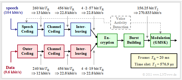
Below you can see the block diagram of the GSM transmission system at the transmitting end, which is
- is suitable for both digitized voice signals $($sampling rate: $8 \ \rm kHz$, quantization: $13$ bit ⇒ data rate: $104 \ \rm kbit/s)$
- as well as being suitable for $9.6 \ \rm kbit/s$ data signals.
Components for voice are shown in blue, those for data in red, and common blocks in green.
Here is a brief description of each component:
- Speech signals are compressed by voice coding from $104 \ \rm kbit/s$ to $13 \ \rm kbit/s$ - i.e. by a factor $8$. The bit rate given in the graph is for the full rate codec, which delivers $($duration $T_{\rm R} = 20\ \rm ms)$ exactly $260$ bits per speech frame.
- The AMR codec delivers in highest mode $12.2 \ \rm kbit/s$ $(244$ bits per speech frame$)$. However, the speech codec must also transmit additional information regarding the current mode, so the data rate before channel coding is also $13 \rm kbit/s$ .
- The task of the dashed Voice Activity Detection' is to decide whether the current voice frame actually contains a voice signal or just a voice pause during which the power of the transmit amplifier should be turned down.
- By channel coding redundancy is added again to allow error correction at the receiver. Per voice frame, the channel encoder outputs $456$ bits, resulting in the data rate $22.8 \ \rm kbit/s$ . The more important bits are specially protected.
- The interleaver scrambles the resulting bit sequence to reduce the influence of bundle errors. The $456$ input bits are split into four time frames of $114$ bits each. Thus, two consecutive bits are always transmitted in two different bursts.
- A data channel - marked in red in the figure - differs from a voice channel (marked in blue) only by the different input rate $(9.6 \ \rm kbit/s$ instead of $104 \ \rm kbit/s)$ and the use of a second, outer channel encoder instead of the voice encoder.
The components highlighted in green apply equally to voice and data transmission. The first common system component for voice and data transmission in the block diagram of the GSM transmitter is the encryption, which is intended to prevent unauthorized persons from gaining access to the data.
There are two fundamentally different encryption methods:
- Symmetric encryption: This knows only one secret key, which is used both for encrypting and enciphering the messages in the sender and for decrypting and deciphering them in the receiver. The key must be generated prior to communication and exchanged between the communication partners via a secure channel. The advantage of this encryption method used in conventional GSM is that it works very quickly.
- Asymmetric encryption: This method uses two independent but matching asymmetric keys. It is not possible to use one key to calculate the other. The "Public Key" is publicly available and is used for encryption. The "Private Key" is secret and used for decryption. In contrast to the symmetric encryption methods, the asymmetric methods are much slower, but also offer higher security.
The second green block is the bursting, where there are different burst types. In Normal Burst the $114$ encoded, scrambled and encrypted bits are mapped to $156.25$ bits by adding Guard Period, signaling bits, etc. These are transmitted within a time slot of duration $T_{\rm Z} = 576.9 \rm µ s$ by means of the modulation method "GMSK". This results in the gross data rate $270.833 \ \rm kbit/s$.
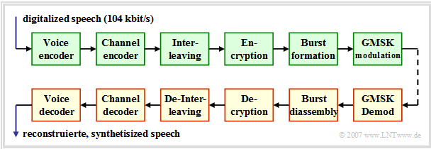
At the receiver there are in reverse order the blocks
- Demodulation,
- burst decomposition,
- decryption,
- de-interleaving,
- channel decoding,
- voice decoding.
On the next pages all blocks of the above transmission scheme are presented in detail.
Coding for voice signals
Uncoded radio data transmission leads to bit error rates in the percentage range. However, with Channel Coding some transmission errors can be detected or even corrected at the receiver. The bit error rate can thus be reduced to values smaller than $10^{-5}$.
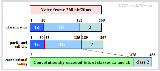
First, we consider GSM channel coding for voice channels, assuming as voice coder the "Full Rate Codec" . The channel coding of a voice frame of $20\ \rm ms$ duration is done in four consecutive steps according to the diagram.
From the description in chapter "Voice Coding" it can be seen that not all $260$ bits have the same influence on the subjectively perceived voice quality.
- Therefore, the data are divided into three classes according to their importance: The $50$ most important bits form the Class 1a, other $132$ are assigned to Class 1b and the remaining $78$ bits result in the rather unimportant Class 2.
- In the next step, a three-bit long "Cyclic Redundancy Check" (CRC) checksum is calculated for the $50$ particularly important bits of class 1a using a feedback shift register. The generator polynomial for this CRC check is:
- $$G_{\rm CRC}(D) = D^3 + D +1\hspace{0.05cm}. $$
- Subsequently, four (yellow) tail bits "0000" are added to the total of $185$ bits of class 1a and 1b including the three (red drawn) CRC parity bits. These four bits initialize the four memory registers of the following convolutional code with $0$ each, so that for each language frame a defined status can be assumed.
- The convolutional code with code rate $R_{\rm C} = 1/2$ doubles these $189$ most important bits to $378$ bits and thus significantly protects them against transmission errors. Then the $78$ bits of the less important class 2 are appended unprotected.
- This way, after channel coding, there are exactly $456$ bits per $20 \ \rm ms$ language frame. This corresponds to a (coded) data rate of $22.8\ \rm kbit/s$ compared to $13\ \rm kbit/s$ after speech coding. The effective channel coding rate is thus $260/456 = 57\%$.
Interleaving for voice signals
The result of convolutional decoding depends not only on the frequency of the transmission errors, but also on their distribution. To achieve good correction results, the channel should not have any memory, but should provide statistically independent bit errors as far as possible.
In mobile radio systems, however, transmission errors usually occur in blocks (error bursts) . By using the interleaving technique, such bundle errors are evenly distributed over several bursts and thus their effects are mitigated.
For a voice channel, the interleaver works in the following way:
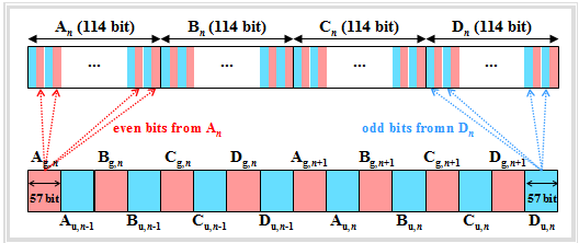
- The $456$ input bits per speech frame are divided into four blocks of $114$ bits each according to a fixed algorithm. We denote these for the $n$-th speech frame by $A_n$, $B_n$, $C_n$ and $D_n$. The index $n-1$ denotes the preceding frame and $n+1$ the succeeding one.
- The block $A_n$ is further divided into two sub-blocks $A_{{\rm g},\hspace{0.05cm}n}$ and $A_{{\rm u},\hspace{0.05cm}n}$ of $57$ bits each, where $A_{{\rm g},\hspace{0.05cm}n}$ denote only the even bit positions and $A_{{\rm u},\hspace{0.05cm}n}$ denote the odd bit positions of $A_n$ . In the graph, $A_{{\rm g},\hspace{0.05cm}n}$ and $A_{{\rm u},\hspace{0.05cm}n}$ can be recognized by the red and blue backgrounds, respectively.
- The subblock $A_{{\rm g},\hspace{0.05cm}n}$ of the $n$-th language frame is identified with the block $A_{{\rm u},\hspace{0.05cm}n-1}$ of the previous frame and gives the $114$ payload of a normal burst: $\left (A_{{\rm g},\hspace{0.05cm}n}, A_{{\rm u},\hspace{0.05cm}n-1}\right )$. The same applies to the next three bursts: $\left (B_{{\rm g},\hspace{0.05cm}n}, B_{{\rm u},\hspace{0.05cm}n-1}\right )$, $\left (C_{{\rm g},\hspace{0.05cm}n}, C_{{\rm u},\hspace{0.05cm}n-1}\right )$, $\left (D_{{\rm g},\hspace{0.05cm}n}, D_{{\rm u},\hspace{0.05cm}n-1}\right )$.
- In the same way, the odd subblocks of the $n$-th language frame are nested with the even sub-blocks of the following frame: $\left (A_{{\rm g},\hspace{0.05cm}n+1}, A_{{\rm u},\hspace{0.05cm}n}\right )$, ... , $\left (D_{{\rm g},\hspace{0.05cm}n+1}, D_{{\rm u},\hspace{0.05cm}n}\right )$.
$\text{Conclusion:}$ The scrambling type described here is called block-diagonal interleaving here specifically of degree $8$:
- This reduces the susceptibility to bunching errors.
- So two consecutive bits of a data block are never sent directly after each other.
- Multi-bit errors occur in isolation after the de-interleaver and can thus be corrected more effectively.
Codierung und Interleaving bei Datensignalen
Für die GSM–Datenübertragung steht jedem Teilnehmer lediglich eine Nettodatenrate von $9.6\ \rm kbit/s$ zur Verfügung. Zur Fehlersicherung werden zwei Verfahren eingesetzt:
- Forward Error Correction (FEC, deutsch: Vorwärtsfehlerkorrektur) wird auf der physikalischen Schicht durch Anwendung von Faltungscodes realisiert.
- Automatic Repeat Request (ARQ); dabei werden auf der Sicherungsschicht defekte und nicht korrigierbare Pakete neu angefordert.
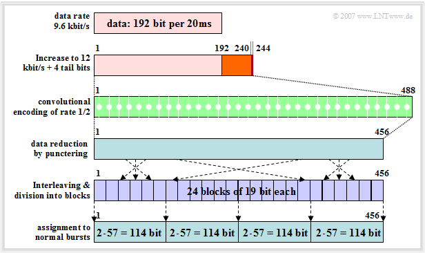
Die Grafik verdeutlicht Kanalcodierung und Interleaving für den Datenkanal mit $9.6\ \rm kbit/s$, die im Gegensatz zur Kanalcodierung des Sprachkanals $($mit Bitfehlerrate $10^{–5}$... $10^{–6})$ eine nahezu fehlerfreie Rekonstruktion der Daten erlaubt:
- Die Datenbitrate von $9.6\ \rm kbit/s$ wird zuerst im Terminal Equipment der Mobilstation durch eine nicht GSM–spezifische Kanalcodierung um $25\%$ auf $12\ \rm kbit/s$ erhöht, um eine Fehlererkennung in leitungsvermittelten Netzen zu ermöglichen.
- Bei der Datenübertragung sind alle Bit gleichwertig, so dass es im Gegensatz zur Codierung des Sprachkanals keine Klassen gibt. Die $240$ Bit pro $20 \ \rm ms$–Zeitrahmen werden zusammen mit vier Tailbits $0000$ zu einem einzigen Datenrahmen zusammengefasst.
- Diese $244$ Bit werden wie bei Sprachkanälen durch einen Faltungscoder der Rate $1/2$ auf $488$ Bit verdoppelt. Pro einlaufendem Bit werden zwei Codesymbole erzeugt, zum Beispiel gemäß den Generatorpolynomen $G_0(D) = 1 + D^3 + D^4$ und $G_1(D) = 1 + D + D^3 + D^4$:
- Der nachfolgende Interleaver erwartet – ebenso wie ein „Sprach–Interleaver” – als Eingabe nur $456$ Bit pro Rahmen. Deshalb werden von den $488$ Bit am Ausgang des Faltungscodierers noch $32$ Bit an den Positionen $15 · j - 4 \ ( j = 1$, ... ,$ 32 )$ entfernt („Punktierung”).
- Da die Datenübertragung weniger zeitkritisch ist als die Sprachübertragung, wird hier ein höherer Interleaving–Grad gewählt. Die $456$ Bit werden auf bis zu $24$ Interleaver–Blöcke zu je $19$ Bit verteilt, was bei Sprachdiensten aus Gründen der Echtzeitübertragung nicht möglich wäre.
- Danach werden die $456$ Bit auf vier aufeinander folgende Normal Bursts aufgeteilt und versandt. Beim Einpacken in die Bursts werden wieder Gruppierungen gerader und ungerader Bits gebildet, ähnlich dem Interleaving im Sprachkanal.
Empfängerseite der GSM–Strecke – Decodierung
Der GSM–Empfänger (gelb hinterlegt) beinhaltet die GMSK-Demodulation, die Burstzerlegung, die Entschlüsselung, das De–Interleaving sowie die Kanal– und Sprachdecodierung.
Zu den beiden letzten Blöcken in obigem Bild ist anzumerken:
- Das Decodierverfahren wird durch die GSM–Spezifikation nicht vorgeschrieben, sondern ist den einzelnen Netzbetreibern überlassen. Die Leistungsfähigkeit ist vom eingesetzten Algorithmus zur Fehlerkorrektur abhängig.
- Zum Beispiel wird beim Decodierverfahren Maximum Likelihood Sequence Estimation (MLSE) die wahrscheinlichste Bitsequenz unter Verwendung des Viterbi–Algorithmus oder eines MAP–Empfängers (Maximum A–posteriori Probability) ermittelt.
- Nach der Fehlerkorrektur wird der Cyclic Redundancy Check (CRC) durchgeführt, wobei beim Vollraten–Codec der Grad des verwendeten CRC–Generatorpolynoms $G= 3$ ist. Damit werden alle Fehlermuster bis zum Gewicht $3$ und alle Bündelfehler bis zur Länge $4$ erkannt.
- Anhand des CRC wird über die Verwendbarkeit eines jeden Sprachrahmens entschieden. Ist das Testergebnis positiv, so werden im nachfolgenden Sprachdecoder aus den Sprachparametern $(260$ Bit pro Rahmen$)$ die Sprachsignale synthetisiert.
- Sind Rahmen ausgefallen, so werden die Parameter früherer, als korrekt erkannter Rahmen zur Interpolation verwendet ⇒ Fehlerverschleierung. Treten mehrere nicht korrekte Sprachrahmen in Folge auf, so wird die Leistung kontinuierlich bis hin zur Stummschaltung abgesenkt.
Aufgabe zum Kapitel
Aufgabe 3.7: Komponenten des GSM–Systems
