Difference between revisions of "Examples of Communication Systems/Methods to Reduce the Bit Error Rate in DSL"
| Line 134: | Line 134: | ||
| − | ==DSL error correction measures | + | ==Overview of DSL error correction measures== |
<br> | <br> | ||
In order to reduce the bit error rate of xDSL systems, a number of techniques have been cleverly combined in the specifications to counteract the two most common causes of errors: | In order to reduce the bit error rate of xDSL systems, a number of techniques have been cleverly combined in the specifications to counteract the two most common causes of errors: | ||
| Line 152: | Line 152: | ||
*The task of the scrambler is to convert long sequences of ones and zeros to produce more frequent signal changes. | *The task of the scrambler is to convert long sequences of ones and zeros to produce more frequent signal changes. | ||
*This is followed by forward error correction (FEC) to detect and possibly correct byte errors at the receiving end. <br>The standard for xDSL is Reed-Solomon coding, often Trellis coding is also used. | *This is followed by forward error correction (FEC) to detect and possibly correct byte errors at the receiving end. <br>The standard for xDSL is Reed-Solomon coding, often Trellis coding is also used. | ||
| − | *The task of the ''interleaver'' is to distribute the received | + | *The task of the ''interleaver'' is to distribute the received code words over a larger time range in order to also distribute any transmission interference that may occur over several code words and thus increase the chances of reconstruction. |
*After passing through the individual bit protection procedures, the data streams from the Fast and Interleaved paths are combined and processed in ''Tone Ordering'' . Here the bits are also assigned to the carrier frequencies (bins). | *After passing through the individual bit protection procedures, the data streams from the Fast and Interleaved paths are combined and processed in ''Tone Ordering'' . Here the bits are also assigned to the carrier frequencies (bins). | ||
*In addition, a guard interval and cyclic prefix are inserted in the DMT transmitter after the IDFT, which is removed again in the DMT receiver. This represents a very simple realization of signal equalization in the frequency domain when the channel is distorted. | *In addition, a guard interval and cyclic prefix are inserted in the DMT transmitter after the IDFT, which is removed again in the DMT receiver. This represents a very simple realization of signal equalization in the frequency domain when the channel is distorted. | ||
| Line 181: | Line 181: | ||
| − | ==Scrambler and | + | ==Scrambler and de–scrambler== |
<br> | <br> | ||
The task of the scrambler is to convert long sequences of ones and zeros in such a way that frequent symbol changes occur. | The task of the scrambler is to convert long sequences of ones and zeros in such a way that frequent symbol changes occur. | ||
| Line 210: | Line 210: | ||
==Forward error correction== | ==Forward error correction== | ||
<br> | <br> | ||
| − | + | For forward error correction (FEC), all xDSL variants use a [[Channel_Coding/Definition_and_Properties_of_Reed-Solomon_Codes|"Reed-Solomon-Code"]] (RS coding). In some systems - for example, Deutsche Telekom's ADSL - ''Trellis Code Modulation'' (TCM) has been made mandatory as an additional error protection measure, even though it has only been specified as "optional" by the international bodies. | |
| − | + | Both methods are discussed in detail in the book ''[[Channel_Coding]]' . Here follows a brief summary of Reed-Solomon coding with respect to its application to DSL: | |
| − | * | + | *With Reed-Solomon coding, redundancy bytes are generated for fixed agreed interpolation points of the payload polynomial. With systematic RS coding, a parity-check value is calculated similar to the CRC procedure and appended to the data block to be protected. |
| − | * | + | *However, the data is no longer processed bit by bit, but byte by byte. Consequently, arithmetic operations are no longer performed in the Galois field $\rm GF( 2 )$ but in $\rm GF(2^8)$. |
| − | + | The Reed-Solomon check digit can also be determined as the division remainder of a polynomial division, for xDSL with the following parameters: | |
| − | * | + | *number $S$ of DMT symbols to be monitored per Reed-Solomon code word $(S \ge 1$ for the fast buffer, $S =2^0$, ... , $2^4$ for the interleaved buffer$)$, |
| − | * | + | *number $K$ of user data bytes in the $S$ DMT symbols, defined as a polynomial $B(x)$ of degree $K$, where the "B" indicates bytes, |
| − | * | + | *Number $R$ of RS parity-check bytes $($even number between $2$ to $16)$ per parity-check value ("Fast" or "Interleaved"), |
| − | * | + | *Sum $N = K + R$ of the user data bytes and check bytes of the Reed-Solomon code word. |
| − | + | The specifics of Reed-Solomon coding for xDSL are given here without further comment: | |
| − | * | + | *For xDSL, the number $R$ of check bytes must be an integer multiple of the number of symbols $S$ so that they can be evenly distributed in the payload polynomial. |
| − | * | + | *The so-called [https://en.wikipedia.org/wiki/Singleton_bound#MDS_codes "MDS codes"] (''Maximum Distance Separable'') - a subclass of RS codes - allow the correction of $R/2$ corrupted user data bytes. |
| − | * | + | *From the selected Reed-Solomon code for the DMT systems, the constraint is a maximum code word length of $2^8-1 = 255$ bytes corresponding to $2040$ bits. |
| − | * | + | *The redundancy of the Reed-Solomon codes can generate a considerable amount of data if the code parameters are unfavorable, thus considerably reducing the net transmission rate. |
| − | * | + | *It is recommended that the data transfer amount (''gross data rate'') be divided judiciously into useful data (net data rate, ''payload'') and error protection data (''overhead''). |
| − | * | + | *Reed-Solomon coding achieves a high coding gain. A system without coding would have to have SNR larger by $3 \ \rm dB$ for the same bit error rate. |
| − | * | + | *By ''trellis-coded modulation'' (TCM) in combination with the other error protection measures, the coding gain turns out to be highly variable; it ranges between $0 \ \rm dB$ and $6 \ \rm dB$. |
| − | ==Interleaving | + | ==Interleaving and de–interleaving== |
<br> | <br> | ||
| − | + | The common task of interleaver (at the sender) and de-interleaver (at the receiver) is to spread the received Reed-Solomon code words over a larger time range in order to distribute any transmission errors that may occur over several code words and thus increase the chance of correct decoding. | |
| − | + | Interleaving is characterized by the parameter $D$ ("depth"), which can take values between $2^0$ and $2^9$ . | |
| − | [[File:P_ID1961__Bei_T_2_4_S8a_v1.png|right|frame| | + | [[File:P_ID1961__Bei_T_2_4_S8a_v1.png|right|frame|For DSL interleaving with $D = 2$]] |
{{GraueBox|TEXT= | {{GraueBox|TEXT= | ||
| − | $\text{ | + | $\text{Example 4:}$ The graphic illustrates the principle using the Reed-Solomon code words $A$, $B$, $C$ with five bytes each and the interleaver depth $D = 2$. |
| − | + | Each byte $B_i$ of the middle Reed-Solomon code word $B$ is delayed by $V_i = (D - 1) - i$ bytes and two interleaver blocks are formed: | |
| − | * | + | *The first block contains the bytes $B_0$, $B_1$ and $B_2$ together with the bytes $A_3$ and $A_4$ of the previous code word. |
| − | * | + | *The second block contains the bytes $B_3$ and $B_4$ along with the bytes $C_0$, $C_1$ and $C_2$ of the following code word.}} |
| − | + | This "scrambling" has the following advantages (provided, $D$ is sufficiently large): | |
| − | * | + | *The error correction capabilities of the Reed-Solomon code are improved. |
| − | * | + | *The user data rate remains the same, i.e. is not reduced (freedom from redundancy). |
| − | * | + | *In the event of faults, entire packets do not have to be repeated at the protocol level. |
| − | + | A disadvantage is that with increasing interleaver depth $D$ there can be noticeable delay times (on the order of milliseconds), which causes major problems for real-time applications. However, interleaving with low depth is only useful if the signal-to-noise ratio is sufficiently high. | |
{{GraueBox|TEXT= | {{GraueBox|TEXT= | ||
| − | $\text{ | + | $\text{Example 5:}$ |
| − | + | An example of the advantages of interleaver/de-interleaver in the presence of bundle errors is shown in the graph below: | |
| − | *In | + | *In the first row, the byte sequences are shown according to Reed-Solomon coding, with each code word consisting of seven bytes as an example. |
| − | *In | + | *In the middle row, the data bytes are shifted by interleaving with $D = 3$ so that between $C_i$ and $C_{i+1}$ there are two foreign bytes and the code word is distributed over three blocks. |
| − | * | + | *Now suppose that during transmission a pulse glitch corrupted three consecutive bytes in a single data block. |
| − | * | + | *After the de-interleaver, the original byte sequence of the Reed-Solomon code words is restored, with the three corrupted bytes distributed among three independent code words. |
| − | * | + | *If two redundancy bytes were inserted in each case during Reed-Solomon coding, the now separated byte corruptions can be completely corrected. |
| − | [[File:P_ID1962__Bei_T_2_4_S8b_v1.png|center|frame| | + | [[File:P_ID1962__Bei_T_2_4_S8b_v1.png|center|frame|DSL interleaving with $D = 3$]]}} |
| − | ==Gain | + | ==Gain scaling and tone ordering== |
<br> | <br> | ||
| − | + | A particularly advantageous feature of DMT is the possibility to adjust the bins individually to the existing channel characteristics and possibly to switch off "bins" with unfavorable SNR completely. The procedure is as follows: | |
| − | [[File:P_ID1963__Bei_T_2_4_S9_v1.png|right|frame|Bit- | + | [[File:P_ID1963__Bei_T_2_4_S9_v1.png|right|frame|Bit-bin assignment based on SNR]] |
| − | * | + | *Before starting the transmission - and possibly also dynamically during operation - the DMT modem measures the channel characteristics for each "bin" and sets the maximum transmission rate individually according to the SNR (see graphic). |
| − | * | + | *During initialization, the ''ADSL Transceiver Units'' exchange bin information, for example the respective "Bits/Bin" and the required transmission power (''Gain''). Thereby the $\rm ATU-C$ sends information about the upstream and the $\rm ATU-R$ sends information about the downstream. |
| − | * | + | *This message is of the form $\{b_i, g_i\}$ where $b_i$ (4 bits) indicates the size of the constellation. For the upstream, the index $i = 1$, ... , $31$ and for the downstream $i = 1$, ... , $255$. |
| − | * | + | *The gain $g_i$ is a fixed-point number with twelve bits. For example $g_i = 001.010000000$ represents the decimal value $1 + 1/4 =1.25$. This indicates that the signal power of channel $i$ must be higher by $1.94 \ \rm dB$ than the power of the test signal transmitted during channel analysis. |
<br clear=all> | <br clear=all> | ||
Beim gleichzeitigen Betrieb des Fast– und des Interleaved–Pfades (siehe [[Examples_of_Communication_Systems/Verfahren_zur_Senkung_der_Bitfehlerrate_bei_DSL#DSL.E2.80.93Fehlerkorrekturma.C3.9Fnahmen_im_.C3.9Cberblick|Grafik]] auf der Seite "DSL–Fehlerkorrekturmaßnahmen") kann durch eine optimierte Trägerfrequenzbelegung (''Tone Ordering'') die Bitfehlerrate weiter gesenkt werden. Hintergrund dieser Maßnahme ist wieder das ''Clipping'' (Abschneiden von Spannungsspitzen), wodurch das SNR insgesamt verschlechtert wird. Dieses Verfahren beruht auf folgenden Regeln: | Beim gleichzeitigen Betrieb des Fast– und des Interleaved–Pfades (siehe [[Examples_of_Communication_Systems/Verfahren_zur_Senkung_der_Bitfehlerrate_bei_DSL#DSL.E2.80.93Fehlerkorrekturma.C3.9Fnahmen_im_.C3.9Cberblick|Grafik]] auf der Seite "DSL–Fehlerkorrekturmaßnahmen") kann durch eine optimierte Trägerfrequenzbelegung (''Tone Ordering'') die Bitfehlerrate weiter gesenkt werden. Hintergrund dieser Maßnahme ist wieder das ''Clipping'' (Abschneiden von Spannungsspitzen), wodurch das SNR insgesamt verschlechtert wird. Dieses Verfahren beruht auf folgenden Regeln: | ||
Revision as of 21:30, 10 March 2023
Contents
- 1 Transmission properties of copper cables
- 2 Noise during transmission
- 3 Signal–to–noise ratio, range and transmission rate
- 4 Overview of DSL error correction measures
- 5 Cyclic redundancy check
- 6 Scrambler and de–scrambler
- 7 Forward error correction
- 8 Interleaving and de–interleaving
- 9 Gain scaling and tone ordering
- 10 Einfügen von Guard–Intervall und zyklischem Präfix
- 11 Aufgaben zum Kapitel
- 12 Quellenverzeichnis
Transmission properties of copper cables
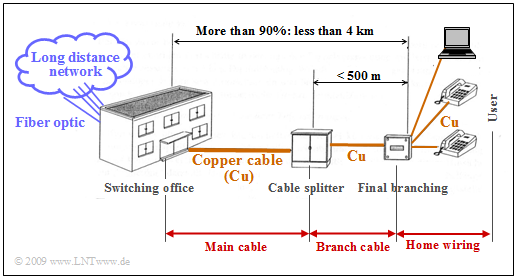
As already mentioned in the chapter "General Description of DSL" , the telephone line network of Deutsche Telekom mainly uses balanced copper pairs with a diameter of $\text{0.4 mm}$ . The last mile is divided into three segments:
- the main cable,
- the branch cable,
- the house connection cable.
On average, the line length is less than four kilometers. In cities, the copper line is shorter than $90\%$ of all cases $\text{2.8 km}$.
The $\rm xDSL$ variants discussed here were developed specifically for use on such symmetrical balanced copper pairs in the cable network. In order to better understand the technical requirements for the xDSL systems, a closer look must be taken at the transmission characteristics and interference on the conductor pairs. This topic has already been dealt with in detail in the fourth main chapter Properties of Electrical Lines of the book "Linear and Time Invariant Systems" and is therefore only briefly summarized here using the "equivalent circuit" :
- Line transmission properties are fully characterized by the characteristic impedance $Z_{\rm W}(f)$ and the transmission coefficient $γ(f)$ . Both quantities are generally complex.
- The attenuation coefficient $α(f)$ is the real part of the transmission measure and describes the damping of the wave propagating along the line; $α(f)$ is an even function of frequency.
- The odd imaginary part $β(f)$ of the complex transmission measure is called phase coefficient and gives the phase rotation of the signal wave along the line.
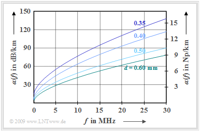
$\text{Example 1:}$ As an example, we consider the attenuation coefficient shown on the right, which is based on empirical investigations by Deutsche Telekom.
The curves were obtained by averaging over a large number of measured lines of one kilometer length in the frequency range up to $\text{30 MHz}$. One can see:
- The attenuation coefficient $α(f)$ increases approximately proportionally with the square root of the frequency and decreases with increasing conductor diameter $d$ .
- The attenuation function $a(f)$ increases linearly with cable length $l$ :
- $$a(f) = α(f) · l.$$
Note the difference between
- "$a$" (for the attenuation function) and
- "$alpha$" (for the attenuation coefficient, with respect to length).
For the line diameter $\text{0.4 mm}$ was given in [PW95][1] an empirical approximation formula for the attenuation coefficient given:
- $$\alpha(f) = \left [ 5.1 + 14.3 \cdot \left (\frac{f}{\rm 1\,MHz}\right )^{0.59} \right ] \frac{\rm dB}{\rm km} \hspace{0.05cm}.$$
Evaluating this equation, the following exemplary values can be given:
- The attenuation $a(f)$ of a balanced copper wire of length $l = 1 \ \rm km$ with diameter $0.4 \ \rm mm$ is slightly more than $60\ \rm dB$ for signal frequency $10\ \rm MHz$ .
- At twice the frequency $(20 \ \rm MHz)$ the attenuation value increases to over $90 \ \rm dB$. It can be seen that the attenuation does not increase exactly with the root of the frequency, as would be the case if the skin effect were considered alone, since several other effects also contribute to the attenuation.
- If the cable length is doubled to $l = 2 \ \rm km$ the attenuation reaches a value of more than $120 \ \rm dB$ $($at $10 \ \rm MHz)$, which corresponds to an amplitude attenuation factor smaller than $10^{-6}$ .
- Due to the frequency dependence of $α(f)$ and $β(f)$ both intersymbol interference $\rm (ISI)$ and inter–carrier–interference $\rm (ICI)$ occur. Suitable equalization must therefore be provided for xDSL.
In the chapter "Properties of balanced copper pairs" of the book "Linear Time-Invariant Systems" this topic is treated in detail. We refer to the two interactive applets "Attenuation of copper cables" and "Time behavior of copper cables".
Noise during transmission
Every message system is affected by noise, which usually results primarily from thermal resistance noise. In addition, for a two-wire line, there are:
- Reflections: The counter-propagating wave increases the attenuation of a pair of lines, which is taken into account in the "operational attenuation" of the line. To prevent such reflection, the terminating resistor $Z_{\rm E}(f)$ would have to be chosen identical to the (complex and frequency-dependent) characteristic impedance $Z_{\rm W}(f)$ . This is difficult in practice. Therefore, the terminating resistors are chosen to be real and constant, and the resulting reflections are combated - if possible - by technical means.
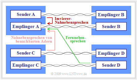
- Crosstalk: This is dominant interference in conducted transmission. Crosstalk occurs when inductive and capacitive couplings between adjacent cores of a cable bundle cause mutual interference during signal transmission.
Crosstalk is divided into two types (see graphic):
- Near End Crosstalk (NEXT): The interfering transmitter and the interfered receiver are on the same side of the cable.
- Far End Crosstalk (FEXT): The interfering transmitter and the interfered receiver are on opposite sides of the cable.
Far-end crosstalk decreases sharply with increasing cable length due to attenuation, so that near-end crosstalk is dominant even with DSL.
$\text{Conclusion:}$ To summarize:
- As frequency increases and spacing between pairs of conductors decreases - as within a star quad - near-end crosstalk increases. It is less critical if the conductors are in different basic bundles.
- Depending on the stranding technique used, the shielding and the manufacturing accuracy of the cable, this effect occurs to varying degrees. The cable length, on the other hand, does not play a role in near-end crosstalk: The own transmitter is not attenuated by the cable.
- Crosstalk can be significantly reduced by clever assignment, for example by assigning different services to adjacent pairs, using different frequency bands with as little overlap as possible.
Signal–to–noise ratio, range and transmission rate
To evaluate the quality of a transmission system, the signal-to-noise ratio (SNR) is usually used before the decision maker. This is also a measure of the expected bit error rate (BER).
- Signal and noise in the same frequency band reduce the SNR and lead to a higher bit error rate or - for a given bit error rate - to a lower transmission rate.
- The relationships between transmit power, channel quality (cable attenuation and interference power Korrektur ( noise power?) ) and achievable transmission rate can be illustrated very well by Shannon's channel capacity formula:
- $$C \left [ \frac{\rm bit}{\rm Symbol} \right ] = \frac {1}{2} \cdot \log_2 \left ( 1 + \frac{P_{\rm E}}{P_{\rm N}} \right )= \frac {1}{2} \cdot \log_2 \left ( 1 + \frac{\alpha_{\rm K}^2 \cdot P_{\rm S}}{P_{\rm N}} \right ) \hspace{0.05cm}.$$
The channel capacity $C$ denotes the maximum transmission bit rate at which transmission is possible under ideal conditions (among others, the best possible coding with infinite block length) ⇒ channel coding theorem. For more details, see the fourth main chapter Continuous-Value Information Theory of the book "Information Theory".
We assume that the bandwidth is fixed by the xDSL variant and that near-end crosstalk is the dominant interference. Then the transmission rate can be improved by the following measures:
- For a given transmit power $P_{\rm S}$ and a given medium (for example: balanced copper pairs with 0.4 mm diameter), the receive power that can be used for demodulation $P_{\rm E}$ is increased only by a shorter line length.
- One reduces the interference power $P_{\rm N}$, which for a given bandwidth $B$ would be achieved by increased crosstalk attenuation, which in turn also depends on the transmission method on the adjacent line pairs.
- Increasing the transmit power $P_{\rm S}$ would not be effective here, since a larger transmit power would at the same time have an unfavorable effect on the crosstalk. This measure would only be successful for an AWGN channel (example: coaxial cable).
This listing shows that with xDSL there is a direct correlation between range (line length), transmission rate and the transmission method used. From the following graph, which refers to measurements with 1-DA xDSL methods and 0.4mm copper cables in test systems with realistic interference conditions, one can clearly see these dependencies.
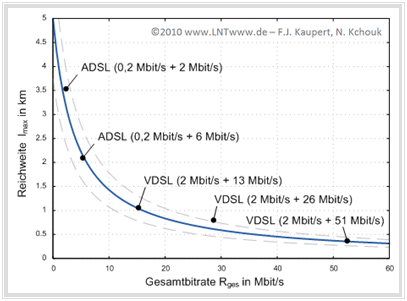
$\text{Example 2:}$ The graph shows
- the range (maximum cable length) $l_{\rm max}$ and
- the total transmission rate $R_{\rm ges}$ of upstream (first indication)
and downstream (second indication).
for some ADSL and VDSL variants.
The total transmission rate for the systems considered is between $2.2 \ \rm Mbit/s$ and $53\ \rm Mbit/s$. The range here refers to a copper twisted pair with 0.4 mm diameter.
The trend of the measured values is shown in this graph as a solid (blue) curve and can be formulated as a rough approximation as follows:
- $$l_{\rm max}\,{\rm \big [in}\,\,{\rm km \big ] } = \frac {20}{4 + R_{\rm ges}\,{\rm \big [in}\,\,{\rm Mbit/s \big ] } } \hspace{0.05cm}.$$
It can be seen that the range of all current systems (approximately between half a kilometer and three and a half kilometers of line length) differs from this rule of thumb by a maximum of $±25\%$ (dashed curves).
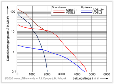
$\text{Example 3:}$ The diagram below shows the total data transmission rates of ADSL2+ and VDSL(2) as a function of line length, with the (different) red curves referring to the downstream and the two blue curves to the upstream. This is based on a worst-case interference scenario with the following boundary conditions:
- Cable bundle with 50 copper pairs (0.4 mm diameter), PE insulated,
- target symbol error rate $10^{-7}, 6 \ \text{dB}$ margin (reserve SNR to reach target data rate),
- simultaneous operation of the following transmission methods:
- 25 times ADSL2+ over ISDN,
- 14 times ISDN, four times SHDSL (1 Mbit/s),
- five times each SHDSL (2 Mbit/s) and VDSL2 band plan 998, and
- twice HDSL.
You can see from this diagram:
- For short line lengths, the achievable transmission rates for VDSL(2) are significantly higher than for ADSL2+.
- From a line length of around 1800 meters, on the other hand, ADSL2+ is significantly better than VDSL(2).
- This is due to the fact that VDSL(2) operates in the lower frequency bands with significantly lower transmission power in order to interfere less with neighboring transmission systems.
- As the line length increases, the higher frequency subchannels become unusable for data transmission due to increasing attenuation, which explains the crash in the data rate.
Overview of DSL error correction measures
In order to reduce the bit error rate of xDSL systems, a number of techniques have been cleverly combined in the specifications to counteract the two most common causes of errors:
- Transmission errors due to impulse and crosstalk interference on the line:
Besonders bei hohen Datenraten liegen benachbarte Symbole im QAM–Signalraum eng beieinander, was die Fehlerwahrscheinlichkeit signifikant erhöht. - Cutting off of signal peaks due to lack of dynamic range of the transmission amplifiers (clipping):
This clipping also corresponds to impulse noise and acts as an additional colored noise load that noticeably degrades the SNR.
In the DMT method, two paths are implemented for error correction measures in the signal processors. The bit assignment to these paths is done by a multiplexer with sync control.
- In the case of the Fast Path, low waiting times (latency) are used.
- With Interleaved-Path low bit error rates are in the foreground. Here the latency is higher due to the use of an interleaver.
- A dual latency means the simultaneous use of both paths. The ADSL Transceiver Units must support dual latency at least in the downstream.
The remaining chapter pages discuss error protection procedures for both paths.
(For other modulation methods, the error protection measures described are the same in principle, but different in detail).
- The transmission chain starts with the Cyclic Redundancy Check (CRC), which forms a checksum over an overframe that is evaluated at the receiver.
- The task of the scrambler is to convert long sequences of ones and zeros to produce more frequent signal changes.
- This is followed by forward error correction (FEC) to detect and possibly correct byte errors at the receiving end.
The standard for xDSL is Reed-Solomon coding, often Trellis coding is also used. - The task of the interleaver is to distribute the received code words over a larger time range in order to also distribute any transmission interference that may occur over several code words and thus increase the chances of reconstruction.
- After passing through the individual bit protection procedures, the data streams from the Fast and Interleaved paths are combined and processed in Tone Ordering . Here the bits are also assigned to the carrier frequencies (bins).
- In addition, a guard interval and cyclic prefix are inserted in the DMT transmitter after the IDFT, which is removed again in the DMT receiver. This represents a very simple realization of signal equalization in the frequency domain when the channel is distorted.
Cyclic redundancy check
The cyclic redundancy check (CRC) is a simple bit-level procedure to check the integrity of data during transmission or duplication. The CRC principle has already been described in detail in the "ISDN chapter" .
Here follows a brief summary, using the nomenclature used in xDSL specifications:
- Prior to data transmission, for a data block $D(x)$ with $k$ bit ⇒ $d_0$, ... , $d_{k-1}$ a parity-check value $C(x)$ with eight bits is formed and appended to the original data sequence. The variable $x$ here denotes a delay operator.
- $C(x)$ is obtained as the division remainder of the polynomial division of $D(x)$ by the parity-check polynomial $G(x)$. This operation is described by modulo-2 equations:
- $$D(x) = d_0 \cdot x^{k-1} + d_1 \cdot x^{k-2} + ... + d_{k-2} \cdot x + d_{k-1}\hspace{0.05cm},$$
- $$G(x) = x^8 + x^4 + x^3 + x^2 + 1 \hspace{0.05cm},$$
- $$C(x) = D(x) \cdot x^8 \,\,{\rm mod }\,\, G(x) = c_0 \cdot x^7 + c_1 \cdot x^6 + \text{...} + c_6 \cdot x + c_7 \hspace{0.05cm}.$$
- At the receiver, a CRC value is formed again using the same procedure and compared with the transmitted check value. If both are unequal, at least one bit error is present.
- This way, bit errors can be detected if they are not too clustered. In ADSL practice, the CRC procedure is sufficient for bit error detection.
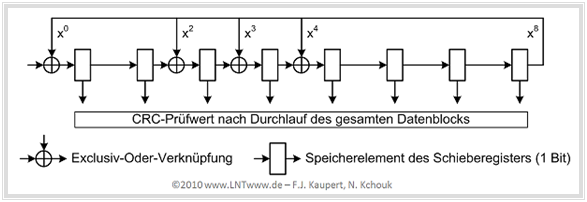
The graphic shows an exemplary circuit - realizable in hardware or software - for CRC parity-check value generation with the generator polynomial specified for ADSL $G(x)$:
- The data block to be tested is introduced into the circuit from the left, the output is fed back and exclusively-or-linked to the digits of the generator polynomial $G(x)$ . After passing through the entire data block, the memory elements contain the CRC parity-check value $C(x)$.
- It should be noted in this context that with ADSL the data is split into so-called superframes (of 68 frames each). Each frame contains data from the fast and interleaved path. In addition, management and synchronization bits are transmitted in specific frames.
- Eight CRC bits are formed per ADSL superframe and per path and are transmitted as Fast Byte and Sync Byte respectively, as the first byte of frame $0$ of the next superframe.
Scrambler and de–scrambler
The task of the scrambler is to convert long sequences of ones and zeros in such a way that frequent symbol changes occur.
- A possible realization is a shift register circuit with feedback exclusive-or-linked branches.
- In order to produce the original binary sequence at the receiver, a mirror-image self-synchronizing de-scrambler must be used there.
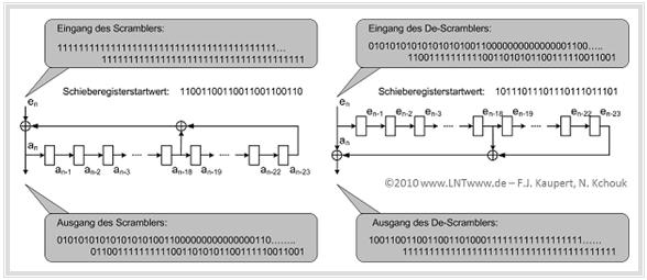
The graphic shows on the left an example of a scrambler actually used at DSL with 23 memory elements. The corresponding de-scrambler is shown on the right.
The transmision side shift register is loaded with an arbitrary initial value that has no further effect on the operation of the circuit. If we denote by $e_n$ the bits of the binary input sequence and by $a_n$ the bits at the output, the following relation holds:
- $$a_n = e_n \oplus a_{n- 18}\oplus a_{n- 23}\hspace{0.05cm}.$$
In the example, the input sequence consists of 80 consecutive ones (upper left gray background), which are shifted bit by bit into the scrambler. The output bit sequence then has frequent one-zero changes, as desired.
The de-scrambler (shown on the right) can be started at any time. The output data stream shows,
- that the de-scrambler initially outputs some (up to a maximum of 23) erroneous bits,
but *then synchronizes automatically and
- then recovers the original bit sequence (only ones) without errors.
Note that for this example, although the bit transfer was assumed to be error-free, the de-scrambler can also be loaded with any starting value, which means that no synchronization is required between the two circuits.
Forward error correction
For forward error correction (FEC), all xDSL variants use a "Reed-Solomon-Code" (RS coding). In some systems - for example, Deutsche Telekom's ADSL - Trellis Code Modulation (TCM) has been made mandatory as an additional error protection measure, even though it has only been specified as "optional" by the international bodies.
Both methods are discussed in detail in the book Channel Coding' . Here follows a brief summary of Reed-Solomon coding with respect to its application to DSL:
- With Reed-Solomon coding, redundancy bytes are generated for fixed agreed interpolation points of the payload polynomial. With systematic RS coding, a parity-check value is calculated similar to the CRC procedure and appended to the data block to be protected.
- However, the data is no longer processed bit by bit, but byte by byte. Consequently, arithmetic operations are no longer performed in the Galois field $\rm GF( 2 )$ but in $\rm GF(2^8)$.
The Reed-Solomon check digit can also be determined as the division remainder of a polynomial division, for xDSL with the following parameters:
- number $S$ of DMT symbols to be monitored per Reed-Solomon code word $(S \ge 1$ for the fast buffer, $S =2^0$, ... , $2^4$ for the interleaved buffer$)$,
- number $K$ of user data bytes in the $S$ DMT symbols, defined as a polynomial $B(x)$ of degree $K$, where the "B" indicates bytes,
- Number $R$ of RS parity-check bytes $($even number between $2$ to $16)$ per parity-check value ("Fast" or "Interleaved"),
- Sum $N = K + R$ of the user data bytes and check bytes of the Reed-Solomon code word.
The specifics of Reed-Solomon coding for xDSL are given here without further comment:
- For xDSL, the number $R$ of check bytes must be an integer multiple of the number of symbols $S$ so that they can be evenly distributed in the payload polynomial.
- The so-called "MDS codes" (Maximum Distance Separable) - a subclass of RS codes - allow the correction of $R/2$ corrupted user data bytes.
- From the selected Reed-Solomon code for the DMT systems, the constraint is a maximum code word length of $2^8-1 = 255$ bytes corresponding to $2040$ bits.
- The redundancy of the Reed-Solomon codes can generate a considerable amount of data if the code parameters are unfavorable, thus considerably reducing the net transmission rate.
- It is recommended that the data transfer amount (gross data rate) be divided judiciously into useful data (net data rate, payload) and error protection data (overhead).
- Reed-Solomon coding achieves a high coding gain. A system without coding would have to have SNR larger by $3 \ \rm dB$ for the same bit error rate.
- By trellis-coded modulation (TCM) in combination with the other error protection measures, the coding gain turns out to be highly variable; it ranges between $0 \ \rm dB$ and $6 \ \rm dB$.
Interleaving and de–interleaving
The common task of interleaver (at the sender) and de-interleaver (at the receiver) is to spread the received Reed-Solomon code words over a larger time range in order to distribute any transmission errors that may occur over several code words and thus increase the chance of correct decoding.
Interleaving is characterized by the parameter $D$ ("depth"), which can take values between $2^0$ and $2^9$ .
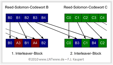
$\text{Example 4:}$ The graphic illustrates the principle using the Reed-Solomon code words $A$, $B$, $C$ with five bytes each and the interleaver depth $D = 2$.
Each byte $B_i$ of the middle Reed-Solomon code word $B$ is delayed by $V_i = (D - 1) - i$ bytes and two interleaver blocks are formed:
- The first block contains the bytes $B_0$, $B_1$ and $B_2$ together with the bytes $A_3$ and $A_4$ of the previous code word.
- The second block contains the bytes $B_3$ and $B_4$ along with the bytes $C_0$, $C_1$ and $C_2$ of the following code word.
This "scrambling" has the following advantages (provided, $D$ is sufficiently large):
- The error correction capabilities of the Reed-Solomon code are improved.
- The user data rate remains the same, i.e. is not reduced (freedom from redundancy).
- In the event of faults, entire packets do not have to be repeated at the protocol level.
A disadvantage is that with increasing interleaver depth $D$ there can be noticeable delay times (on the order of milliseconds), which causes major problems for real-time applications. However, interleaving with low depth is only useful if the signal-to-noise ratio is sufficiently high.
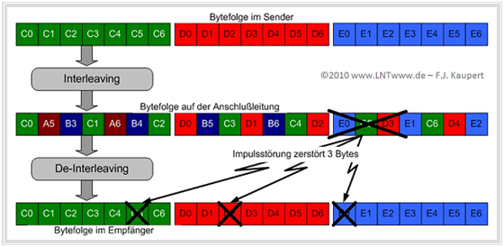
$\text{Example 5:}$ An example of the advantages of interleaver/de-interleaver in the presence of bundle errors is shown in the graph below:
- In the first row, the byte sequences are shown according to Reed-Solomon coding, with each code word consisting of seven bytes as an example.
- In the middle row, the data bytes are shifted by interleaving with $D = 3$ so that between $C_i$ and $C_{i+1}$ there are two foreign bytes and the code word is distributed over three blocks.
- Now suppose that during transmission a pulse glitch corrupted three consecutive bytes in a single data block.
- After the de-interleaver, the original byte sequence of the Reed-Solomon code words is restored, with the three corrupted bytes distributed among three independent code words.
- If two redundancy bytes were inserted in each case during Reed-Solomon coding, the now separated byte corruptions can be completely corrected.
Gain scaling and tone ordering
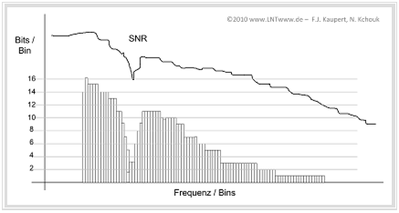
A particularly advantageous feature of DMT is the possibility to adjust the bins individually to the existing channel characteristics and possibly to switch off "bins" with unfavorable SNR completely. The procedure is as follows:
- Before starting the transmission - and possibly also dynamically during operation - the DMT modem measures the channel characteristics for each "bin" and sets the maximum transmission rate individually according to the SNR (see graphic).
- During initialization, the ADSL Transceiver Units exchange bin information, for example the respective "Bits/Bin" and the required transmission power (Gain). Thereby the $\rm ATU-C$ sends information about the upstream and the $\rm ATU-R$ sends information about the downstream.
- This message is of the form $\{b_i, g_i\}$ where $b_i$ (4 bits) indicates the size of the constellation. For the upstream, the index $i = 1$, ... , $31$ and for the downstream $i = 1$, ... , $255$.
- The gain $g_i$ is a fixed-point number with twelve bits. For example $g_i = 001.010000000$ represents the decimal value $1 + 1/4 =1.25$. This indicates that the signal power of channel $i$ must be higher by $1.94 \ \rm dB$ than the power of the test signal transmitted during channel analysis.
Beim gleichzeitigen Betrieb des Fast– und des Interleaved–Pfades (siehe Grafik auf der Seite "DSL–Fehlerkorrekturmaßnahmen") kann durch eine optimierte Trägerfrequenzbelegung (Tone Ordering) die Bitfehlerrate weiter gesenkt werden. Hintergrund dieser Maßnahme ist wieder das Clipping (Abschneiden von Spannungsspitzen), wodurch das SNR insgesamt verschlechtert wird. Dieses Verfahren beruht auf folgenden Regeln:
- Bins mit dichter Konstellation (viele Bits/Bin ⇒ größere Verfälschungswahrscheinlichkeit) werden dem Interleaved–Zweig zugeordnet, da dieser durch den zusätzlichen Interleaver per se zuverlässiger ist. Entsprechend werden die Subkanäle mit niederwertiger Belegung (wenige Bits/Bin) für den Fast–Datenpuffer reserviert.
- Gesendet werden dann neue Tabellen für Upstream und Downstream, in denen die Bins nicht mehr nach dem Index geordnet sind, sondern entsprechend den Bits/Bin–Verhältnissen. Anhand dieser neuen Tabelle ist es für die $\rm ATU–C$ bzw. $\rm ATU–R$ möglich, die Bit–Extraktion erfolgreich durchzuführen.
Einfügen von Guard–Intervall und zyklischem Präfix
Im Kapitel Realisierung von OFDM–Systemen des Buches "Modulationsverfahren" wurde bereits gezeigt, dass durch die Einfügung eines Schutzabstandes – man bezeichnet diesen auch als Guard–Intervall oder Guard–Lücke – die Bitfehlerrate bei Vorhandensein von linearen Kanalverzerrungen entscheidend verbessert werden kann.
Wir gehen davon aus, dass sich die Kabelimpulsantwort $h_{\rm K}(t)$ über die Zeitdauer $T_{\rm K}$ erstreckt. Ideal wäre $h_{\rm K}(t) = δ(t)$ und dementsprechend eine unendlich kurze Ausdehnung: $T_{\rm K} = 0$. Bei verzerrendem Kanal $(T_{\rm K} > 0 )$ gilt:
- Durch Einfügung eines Guard–Intervalls der Dauer $T_{\rm G}$ lassen sich Intersymbolinterferenzen zwischen den einzelnen DSL–Rahmen vermeiden, solange $T_{\rm G}$ ≥ $T_{\rm K}$ gilt. Diese Maßnahme führt allerdings zu einem Ratenverlust um den Faktor $T/(T + T_{\rm G})$ mit der Symboldauer $T = {1}/{f_0}$.
- Damit gibt es aber immer noch Inter–Carrier–Interferenzen zwischen den einzelnen Subträgern innerhalb des gleichen Rahmens, das heißt, die DMT–Einzelspektren sind nicht mehr $\rm si$–förmig und es kommt zu einer De–Orthogonalisierung.
- Durch ein zyklisches Präfix lässt sich auch dieser störende Effekt vermeiden. Dabei erweitert man den Sendevektor $\mathbf{s}$ nach vorne um die letzten $L$ Abtastwerte des IDFT–Ausgangs, wobei der Minimalwert für $L$ durch die Dauer $T_{\rm K}$ der Kabelimpulsantwort vorgegeben ist.
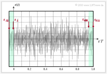
$\text{Beispiel 6:}$ Die Grafik zeigt diese Maßnahme beim DSL/DMT–Verfahren, für das der Parameter $L = 32$ festgelegt wurde.
- Die Abtastwerte $s_{480}$ , ... , $s_{511}$ werden als Präfix $(s_{-32}$ , ... , $s_{-1})$ zum IDFT–Ausgangsvektor $(s_0$ , ... , $s_{511})$ hinzugefügt.
- Das Sendesignal $s(t)$ hat nun statt der Symboldauer $T ≈ 232 \ {\rm µ s}$ die resultierende Dauer $T + T_{\rm G} = 1.0625 \cdot T ≈ 246 \ {\rm µ s}$. Dadurch wird die Rate um den Faktor $0.94$ verringert.
- Bei der empfangsseitigen Auswertung beschränkt man sich auf den Zeitbereich von $0$ bis $T$. In diesem Zeitintervall ist der störende Einfluss der Impulsantwort bereits abgeklungen und die Subkanäle sind – ebenso wie bei idealem Kanal – zueinander orthogonal.
- Die Abtastwerte $s_{-32}$ , ... , $s_{-1}$ werden am Empfänger verworfen – eine recht einfache Realisierung der Signalentzerrung.
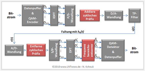
Die letzte Grafik dieses Kapitels zeigt das gesamte DMT–Übertragungssystem, allerdings ohne die vorne beschriebenen Fehlerschutzmaßnahmen. Man erkennt:
- Im Block „Addiere zyklisches Präfix” werden die Abtastwerte $s_{480}$, ... , $s_{511}$ als $s_{-32}$, ... , $s_{-1}$ hinzugefügt. Das Sendesignal $s(t)$ hat somit den im $\text{Beispiel 6}$ gezeigten Verlauf.
- Das Empfangsignal $r(t)$ ergibt sich aus der Faltung von $s(t)$ mit $h_{\rm K}(t)$. Nach A/D–Wandlung und Entfernen des zyklischen Präfix erhält man die Eingangswerte $r_0$, ... , $ r_{511}$ für die DFT.
- Die (komplexen) Ausgangswerte $D_k\hspace{0.01cm}'$ der DFT hängen nur vom jeweiligen (komplexen) Datenwert $D_k$ ab. Unabhängig von anderen Daten $D_κ (κ ≠ k)$ gilt mit dem Rauschwert $n_k\hspace{0.01cm}'$:
- $${D}_k\hspace{0.01cm}' = \alpha_k \cdot {D}_k + {n}_k\hspace{0.01cm}', \hspace{0.2cm}\alpha_k = H_{\rm K}( f = f_k) \hspace{0.05cm}. $$
- Jeder Träger $D_k$ wird durch einen eigenen (komplexen) Faktor $α_k$, der nur vom Kanal abhängt, in seiner Amplitude und Phase verändert. Der Frequenzbereichsentzerrer hat nur die Aufgabe, den Koeffizienten $D_k\hspace{0.01cm}'$ mit dem inversen Wert ${1}/{α_k}$ zu multiplizieren. Man erhält schließlich:
- $$ \hat{D}_k = {D}_k + {n}_k \hspace{0.05cm}.$$
$\text{Fazit:}$
- Diese einfache Realisierungsmöglichkeit der vollständigen Entzerrung des stark verzerrenden Kabelfrequenzgangs war eines der entscheidenden Kriterien, dass sich bei $\rm xDSL$ das $\rm DMT$–Verfahren gegenüber $\rm QAM$ und $\rm CAP$ durchgesetzt hat.
- Meist findet direkt nach der A/D–Wandlung zusätzlich noch eine Vorentzerrung im Zeitbereich statt, um auch die Intersymbolinterferenzen zwischen benachbarten Rahmen zu vermeiden.
Aufgaben zum Kapitel
Aufgabe 2.5: DSL–Fehlersicherungsmaßnahmen
Aufgabe 2.5Z: Reichweite und Bitrate bei ADSL
Aufgabe 2.6: Zyklisches Präfix
Quellenverzeichnis
- ↑ Pollakowski, M.; Wellhausen, H.W.: Properties of symmetrical local access cables in the frequency range up to 30 MHz. Communication from the Research and Technology Center of Deutsche Telekom AG, Darmstadt, Verlag für Wissenschaft und Leben Georg Heidecker, 1995.
