Difference between revisions of "Linear and Time Invariant Systems/Some Low-Pass Functions in Systems Theory"
| Line 22: | Line 22: | ||
{{BlaueBox|TEXT= | {{BlaueBox|TEXT= | ||
$\text{Definition:}$ | $\text{Definition:}$ | ||
| − | An '''ideal low-pass''' is on hand if its frequency response is as follows: | + | An '''ideal low-pass filter''' is on hand if its frequency response is as follows: |
:$$H(f) = \left\{ \begin{array}{l} \hspace{0.25cm}1 \\ 0.5 \\\hspace{0.25cm} 0 \\ \end{array} \right.\quad \quad\begin{array}{*{10}c} \text {for} \\ \text {for} \\ \text {for} \\ \end{array}\begin{array}{*{20}c}{\vert \hspace{0.005cm}f\hspace{0.05cm} \vert< \Delta f/2,} \\{\vert \hspace{0.005cm}f\hspace{0.05cm} \vert = \Delta f/2,} \\{\vert \hspace{0.005cm}f\hspace{0.05cm} \vert > \Delta f/2.} \\\end{array}$$ | :$$H(f) = \left\{ \begin{array}{l} \hspace{0.25cm}1 \\ 0.5 \\\hspace{0.25cm} 0 \\ \end{array} \right.\quad \quad\begin{array}{*{10}c} \text {for} \\ \text {for} \\ \text {for} \\ \end{array}\begin{array}{*{20}c}{\vert \hspace{0.005cm}f\hspace{0.05cm} \vert< \Delta f/2,} \\{\vert \hspace{0.005cm}f\hspace{0.05cm} \vert = \Delta f/2,} \\{\vert \hspace{0.005cm}f\hspace{0.05cm} \vert > \Delta f/2.} \\\end{array}$$ | ||
| − | We sometimes also use the term "Küpfmüller-low- | + | We sometimes also use the term "Küpfmüller-low-pass filter” (KLP) in in memory of the pioneer of systems theory, [https://de.wikipedia.org/wiki/Karl_K%C3%BCpfm%C3%BCller Karl Küpfmüller]. }} |
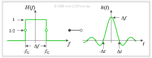
The graph shows such an ideal low-pass filter in the frequency and time domain. The following can be concluded from this curve shape: | The graph shows such an ideal low-pass filter in the frequency and time domain. The following can be concluded from this curve shape: | ||
| − | [[File:P_ID842__LZI_T_1_3_S2_neu.png |right|frame| Ideal Low-pass: Frequency Response and Impulse Response|class=fit]] | + | [[File:P_ID842__LZI_T_1_3_S2_neu.png |right|frame| Ideal Low-pass Filter: Frequency Response and Impulse Response|class=fit]] |
*Due to the abrupt, infinitely steep roll-off the 3dB cut-off frequency $f_{\rm G}$ is here exactly half the system-theoretical bandwidth $Δf$. | *Due to the abrupt, infinitely steep roll-off the 3dB cut-off frequency $f_{\rm G}$ is here exactly half the system-theoretical bandwidth $Δf$. | ||
*All spectral components with $f \lt f_{\rm G}$ are transmitted undistorted (''pass band''). | *All spectral components with $f \lt f_{\rm G}$ are transmitted undistorted (''pass band''). | ||
| Line 35: | Line 35: | ||
*By definition, $H(f) = 0.5$ holds for $f = f_{\rm G}$. | *By definition, $H(f) = 0.5$ holds for $f = f_{\rm G}$. | ||
<br clear=all> | <br clear=all> | ||
| − | '''Description of the ideal low-pass in the time domain:''' | + | '''Description of the ideal low-pass filter in the time domain:''' |
*According to the inverse Fourier transformation the impulse response (see diagram on the right) is | *According to the inverse Fourier transformation the impulse response (see diagram on the right) is | ||
:$$h(t) = \Delta f \cdot {\rm si}(\pi \cdot \Delta f \cdot t)\hspace{0.7cm}{\rm{with}}\hspace{0.7cm}{\rm si}(x) ={\sin(x)}/{x}.$$ | :$$h(t) = \Delta f \cdot {\rm si}(\pi \cdot \Delta f \cdot t)\hspace{0.7cm}{\rm{with}}\hspace{0.7cm}{\rm si}(x) ={\sin(x)}/{x}.$$ | ||
| Line 51: | Line 51: | ||
''Note:'' In some books, instead of the function ${\rm si}(x)$ the similar function ${\rm sinc}(x)$ is used: | ''Note:'' In some books, instead of the function ${\rm si}(x)$ the similar function ${\rm sinc}(x)$ is used: | ||
:$${\rm si}(x) = \frac{\sin(x)}{x}\hspace{0.5cm}\Rightarrow\hspace{0.5cm}{\rm sinc}(x) = \frac{\sin(\pi x)}{\pi x} = {\rm si}(\pi x).$$ | :$${\rm si}(x) = \frac{\sin(x)}{x}\hspace{0.5cm}\Rightarrow\hspace{0.5cm}{\rm sinc}(x) = \frac{\sin(\pi x)}{\pi x} = {\rm si}(\pi x).$$ | ||
| − | Thus, the impulse response of the ideal low-pass is: $h(t)$ = $Δf · {\rm sinc}(Δf · t).$ | + | Thus, the impulse response of the ideal low-pass filter is: $h(t)$ = $Δf · {\rm sinc}(Δf · t).$ |
==Slit Low-Pass Filter== | ==Slit Low-Pass Filter== | ||
| Line 57: | Line 57: | ||
{{BlaueBox|TEXT= | {{BlaueBox|TEXT= | ||
$\text{Definition:}$ | $\text{Definition:}$ | ||
| − | An LTI–system is called a '''slit–low-pass''' if the frequency response has the following form: | + | An LTI–system is called a '''slit–low-pass filter''' if the frequency response has the following form: |
:$$H(f) = {\rm si}(\pi {f}/{ \Delta f})\hspace{0.7cm}{\rm{where} }\hspace{0.7cm}{\rm si}(x) ={\sin(x)}/{x}.$$}} | :$$H(f) = {\rm si}(\pi {f}/{ \Delta f})\hspace{0.7cm}{\rm{where} }\hspace{0.7cm}{\rm si}(x) ={\sin(x)}/{x}.$$}} | ||
| Line 63: | Line 63: | ||
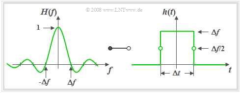
From the graph on the left it can be seen that the frequency response $H_{\rm SLP}(f)$ of the slit–low-pass is identical in shape to the impulse response $h_{\rm KLP}(t)$ of the Küpfmüller-low-pass. | From the graph on the left it can be seen that the frequency response $H_{\rm SLP}(f)$ of the slit–low-pass is identical in shape to the impulse response $h_{\rm KLP}(t)$ of the Küpfmüller-low-pass. | ||
| − | [[File:P_ID844__LZI_T_1_3_S3_neu.png |right|frame| slit– | + | [[File:P_ID844__LZI_T_1_3_S3_neu.png |right|frame| slit–low-pass: frequecy response and respective impulse response|class=fit]] |
According to the [[Signal_Representation/Fourier_Transform_Laws#Vertauschungssatz|Vertauschungssatz]] the impulse response $h_{\rm SLP}(t)$ of the slit low-pass filter must also have the same form as the frequency response $H_{\rm KLP}(f)$ of the ideal low-pass filter. | According to the [[Signal_Representation/Fourier_Transform_Laws#Vertauschungssatz|Vertauschungssatz]] the impulse response $h_{\rm SLP}(t)$ of the slit low-pass filter must also have the same form as the frequency response $H_{\rm KLP}(f)$ of the ideal low-pass filter. | ||
| Line 71: | Line 71: | ||
\end{array}$$ | \end{array}$$ | ||
Based on the graph on the right the following statements can be derived: | Based on the graph on the right the following statements can be derived: | ||
| − | *The slit–low-pass is also noncausal in this form. | + | *The slit–low-pass filter is also noncausal in this form. |
*However, adding a running time of $Δt/2$ renders the system causal and thus realisable. | *However, adding a running time of $Δt/2$ renders the system causal and thus realisable. | ||
| − | *The slit–low-pass acts as an integrator over the time period $Δt$: | + | *The slit–low-pass filter acts as an integrator over the time period $Δt$: |
:$$y(t) = x (t) * h (t) = \frac{1}{\Delta t} \cdot \int\limits_{ t - \Delta t/2 }^{ t + \Delta t/2 } {x ( \tau )} \hspace{0.1cm}{\rm d}\tau.$$ | :$$y(t) = x (t) * h (t) = \frac{1}{\Delta t} \cdot \int\limits_{ t - \Delta t/2 }^{ t + \Delta t/2 } {x ( \tau )} \hspace{0.1cm}{\rm d}\tau.$$ | ||
*If $x(t)$ is a harmonic oscillation with frequency $f_0 = k \cdot Δf$ (where $k$ is an integer), then it integrates exactly over $k$ periods and $y(t) = 0$ holds. This is also shown by the zeros of $H(f)$. | *If $x(t)$ is a harmonic oscillation with frequency $f_0 = k \cdot Δf$ (where $k$ is an integer), then it integrates exactly over $k$ periods and $y(t) = 0$ holds. This is also shown by the zeros of $H(f)$. | ||
Revision as of 19:19, 6 May 2021
Contents
General Remarks
All low-pass functions described on the next pages have the following properties:
- The frequency response $H(f)$ ist real and even, so that according to the Zuordnungssatz the associated impulse response$h(t)$ is always real and even, too.
- Thus, it is obvious that the systems considered here are noncausal and hence not realisable. The description of causal systems is given in the chapter Beschreibung kausaler realisierbarer Systeme of this book.
- The advantage of these systemtheoretic filter functions is the simple description by at most two parameters such that the filter influx can be represented in a transparent way.
- The most important function parameter is the equivalent bandwidth according to the definition via the rectangle of area equal to the square:
- $$\Delta f = \frac{1}{H(f=0)}\cdot \int_{-\infty}^{+\infty}H(f) \hspace{0.15cm} {\rm d}f.$$
- According to the so-called Reziprozitätsgesetz the equivalent time period of the impulse response is thus also fixed, which is also defined via the rectangle of area equal to the square:
- $$\Delta t = \frac{1}{h(t=0)}\cdot \int_{-\infty}^{+\infty}h(t) \hspace{0.15cm} {\rm d}t = \frac{1}{\Delta f}.$$
- The direct signal transmission factor wiris always assumed to be $H(f = 0) = 1$ unless explicitly stated otherwise.
- From every low-pass function corresponding high-pass functions can be derived as shown on the page Herleitung systemtheoretischer Hochpassfunktionen.
Ideal Low-Pass Filter – Küpfmüller Low-Pass Filter
$\text{Definition:}$ An ideal low-pass filter is on hand if its frequency response is as follows:
- $$H(f) = \left\{ \begin{array}{l} \hspace{0.25cm}1 \\ 0.5 \\\hspace{0.25cm} 0 \\ \end{array} \right.\quad \quad\begin{array}{*{10}c} \text {for} \\ \text {for} \\ \text {for} \\ \end{array}\begin{array}{*{20}c}{\vert \hspace{0.005cm}f\hspace{0.05cm} \vert< \Delta f/2,} \\{\vert \hspace{0.005cm}f\hspace{0.05cm} \vert = \Delta f/2,} \\{\vert \hspace{0.005cm}f\hspace{0.05cm} \vert > \Delta f/2.} \\\end{array}$$
We sometimes also use the term "Küpfmüller-low-pass filter” (KLP) in in memory of the pioneer of systems theory, Karl Küpfmüller.
The graph shows such an ideal low-pass filter in the frequency and time domain. The following can be concluded from this curve shape:
- Due to the abrupt, infinitely steep roll-off the 3dB cut-off frequency $f_{\rm G}$ is here exactly half the system-theoretical bandwidth $Δf$.
- All spectral components with $f \lt f_{\rm G}$ are transmitted undistorted (pass band).
- All components with $f \gt f_{\rm G}$ are completely suppressed (cut-off region).
- By definition, $H(f) = 0.5$ holds for $f = f_{\rm G}$.
Description of the ideal low-pass filter in the time domain:
- According to the inverse Fourier transformation the impulse response (see diagram on the right) is
- $$h(t) = \Delta f \cdot {\rm si}(\pi \cdot \Delta f \cdot t)\hspace{0.7cm}{\rm{with}}\hspace{0.7cm}{\rm si}(x) ={\sin(x)}/{x}.$$
- The impulse response $h(t)$ extended to infinity on both sides exhibits equidistant zero-crossings at an interval of $Δt = 1/ Δf$.
- The asymptotic decay is inversely proportional to time:
- $$|h(t)| = \frac{\Delta f}{\pi \cdot \Delta f \cdot |t|} \cdot \left |{\rm sin}(\pi \cdot \Delta f\cdot t )\right | \le \frac{1}{\pi \cdot |t|}.$$
- It follows that the impulse response is certainly less than $1‰$ of the impulse maximum only for times $t \gt t_{1‰} = 318 \cdot \Delta t$ .
- The step response $\sigma(t)$ is obtained from the impulse response by integration and is:
- $${\sigma}(t) = \int_{ - \infty }^{ t } {h ( \tau )} \hspace{0.1cm}{\rm d}\tau = \frac{1}{2} + \frac{1}{\pi} \cdot {\rm Si}(\pi \cdot\Delta f \cdot t ).$$
- Here the so-called integral sine function is used:
- $${\rm Si}(x) = \int_{ 0 }^{ x } {{\rm si} ( \xi )} \hspace{0.1cm}{\rm d}\xi = x - \frac{x^3}{3 \cdot 3!} + \frac{x^5}{5 \cdot 5!} - \frac{x^7}{7 \cdot 7!}+\text{ ...}$$
- It has the following properties:
- $${\rm Si}(0) = 0, \hspace{0.3cm}{\rm Si}(\infty) = \frac{\pi}{2}, \hspace{0.3cm}{\rm Si}(-x) = -{\rm Si}(x).$$
Note: In some books, instead of the function ${\rm si}(x)$ the similar function ${\rm sinc}(x)$ is used:
- $${\rm si}(x) = \frac{\sin(x)}{x}\hspace{0.5cm}\Rightarrow\hspace{0.5cm}{\rm sinc}(x) = \frac{\sin(\pi x)}{\pi x} = {\rm si}(\pi x).$$
Thus, the impulse response of the ideal low-pass filter is: $h(t)$ = $Δf · {\rm sinc}(Δf · t).$
Slit Low-Pass Filter
$\text{Definition:}$ An LTI–system is called a slit–low-pass filter if the frequency response has the following form:
- $$H(f) = {\rm si}(\pi {f}/{ \Delta f})\hspace{0.7cm}{\rm{where} }\hspace{0.7cm}{\rm si}(x) ={\sin(x)}/{x}.$$
From the graph on the left it can be seen that the frequency response $H_{\rm SLP}(f)$ of the slit–low-pass is identical in shape to the impulse response $h_{\rm KLP}(t)$ of the Küpfmüller-low-pass.
According to the Vertauschungssatz the impulse response $h_{\rm SLP}(t)$ of the slit low-pass filter must also have the same form as the frequency response $H_{\rm KLP}(f)$ of the ideal low-pass filter.
Thus, with $Δt = 1/ Δf$ the following holds:
- $$h(t) = \left\{ \begin{array}{l} \hspace{0.25cm}\Delta f \\ \Delta f/2 \\ \hspace{0.25cm} 0 \\ \end{array} \right.\quad \quad \begin{array}{*{10}c} \text{for} \\ \text{for} \\ \text{for} \\ \end{array}\begin{array}{*{20}c} {\vert \hspace{0.005cm}t\hspace{0.05cm} \vert < \Delta t/2,} \\ {\vert \hspace{0.005cm}t\hspace{0.05cm} \vert = \Delta t/2,} \\ {\vert \hspace{0.005cm}t\hspace{0.05cm} \vert > \Delta t/2.} \\ \end{array}$$
Based on the graph on the right the following statements can be derived:
- The slit–low-pass filter is also noncausal in this form.
- However, adding a running time of $Δt/2$ renders the system causal and thus realisable.
- The slit–low-pass filter acts as an integrator over the time period $Δt$:
- $$y(t) = x (t) * h (t) = \frac{1}{\Delta t} \cdot \int\limits_{ t - \Delta t/2 }^{ t + \Delta t/2 } {x ( \tau )} \hspace{0.1cm}{\rm d}\tau.$$
- If $x(t)$ is a harmonic oscillation with frequency $f_0 = k \cdot Δf$ (where $k$ is an integer), then it integrates exactly over $k$ periods and $y(t) = 0$ holds. This is also shown by the zeros of $H(f)$.
Gaussian Low-Pass Filter
Eine häufig für systemtheoretische Untersuchungen verwendete Filterfunktion ist der Gaußtiefpass, der ebenfalls durch nur einen Parameter, nämlich die äquivalente Bandbreite $Δf$, beschreibbar ist.
$\text{Definition:}$ Für den Frequenzgang und die Impulsantwort des Gauß-low-pass gelten:
- $$H(f) = {\rm e}^{-\pi(f/\Delta f)^2}\hspace{0.15cm}\bullet\!\!-\!\!\!-\!\!\!-\!\!\circ\, \hspace{0.15cm}h(t) = \Delta f \cdot {\rm e}^{-\pi(\Delta f \cdot \hspace{0.03cm} t)^2} .$$
Der Name geht auf den Mathematiker, Physiker und Astronomen Carl-Friedrich Gauß zurück. Gauß hat sich zwar nicht selber mit dieser Thematik auseinandergesetzt, aber die mathematische Form von Frequenzgang und Impulsantwort weisen eine Ähnlichkeit mit der so genannten Gaußformel auf, die er für die Wahrscheinlichkeitsrechnung gefunden hat.
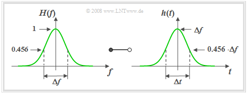
Anhand dieser Grafik können folgende Aussagen getroffen werden:
- Die ebenfalls über das flächengleiche Rechteck definierte äquivalente Impulsdauer $Δt$ ist gleich dem Kehrwert der äquivalenten Bandbreite $Δf$.
- Eine schmalbandige Filterfunktion (kleines $Δf$) führt zu einer breiten (großes $Δt$) und gleichzeitig niedrigen Impulsantwort $h(t)$.
- Das so genannte Reziprozitätsgesetz von Zeitdauer und Bandbreite lässt sich am Beispiel des Gaußtiefpasses besonders anschaulich zeigen.
- Die Frequenz– und Zeitbereichsdarstellungen sind prinzipiell von gleicher Form. Man sagt auch, dass die Gaußfunktion invariant gegenüber der Fouriertransformation ist.
- Aufgrund der unendlichen Ausbreitung seiner Impulsantwort ist der Gaußtiefpass ebenso wie der ideale Tiefpass stark akausal und (exakt) nur mit unendlich großer Laufzeit realisierbar.
- Allerdings ist zu berücksichtigen, dass $h(t)$ bereits bei $t = 1.5 \cdot Δt$ auf $1‰$ seines Maximalwertes abgeklungen ist. Für $t = 3 \cdot Δt$ ergibt sich sogar $h(t) ≈ 5 · 10^{–13} · h(0)$.
- Diese Zahlenwerte machen deutlich, dass man den Gaußtiefpass durchaus auch für praxisnahe Simulationen heranziehen kann, solange Laufzeiten keine systembegrenzende Rolle spielen.
- Die Sprungantwort $σ(t)$ lautet mit der Gaußschen Fehlerfunktion $ϕ(x)$, die in Formelsammlungen meist tabellarisch angegeben wird:
- $$\sigma(t) = \int_{ -\infty }^{ t } {h(\tau)} \hspace{0.1cm}{\rm d}\tau = {\rm \phi}\left( \sqrt{2 \pi }\cdot{t}/{\Delta t} \right) \hspace{0.7cm}{\rm{mit}}\hspace{0.7cm}{\rm \phi}(x) = \frac{1}{\sqrt{2 \pi }} \cdot \int_{ -\infty }^{ x } {{\rm e}^{-u^2/2}} \hspace{0.1cm}{\rm d}u.$$
Trapez–Tiefpass
Die bisher in diesem Kapitel beschriebenen Tiefpassfunktionen hängen nur von einem Parameter – der äquivalenten Bandbreite $Δf$ – ab. Dabei war die Flankensteilheit für einen gegebenen Filtertyp fest vorgegeben.
Nun wird ein Tiefpass mit parametrisierbarer Flankensteilheit beschrieben.
$\text{Definition:}$ Der Frequenzgang des Trapez–Tiefpasses lautet mit den Eckfrequenzen $f_1$ und $f_2 \ge f_1$:
- $$H(f) = \left\{ \begin{array}{l} \hspace{0.25cm}1 \\ \frac{f_2 - \vert f \vert }{f_2 -f_1} \\ \hspace{0.25cm} 0 \\ \end{array} \right.\quad \quad \begin{array}{*{10}c} \text{für} \\ \text{für} \\ \text{für} \\ \end{array}\begin{array}{*{20}c} {\hspace{0.94cm}\vert \hspace{0.005cm} f\hspace{0.05cm} \vert < f_1,} \\ {f_1 \le \vert \hspace{0.005cm} f\hspace{0.05cm} \vert \le f_2,} \\ {\hspace{0.94cm}\vert \hspace{0.005cm} f\hspace{0.05cm} \vert > f_2.} \\ \end{array}$$
Anstelle von $f_1$ und $f_2$ kann man zur Beschreibung von $H(f)$ auch folgende Parameter verwenden:
- die äquivalente Bandbreite, ermittelt über das flächengleiche Rechteck:
- $$\Delta f = f_1 + f_2.$$
- der Rolloff-Faktor (im Frequenzbereich) als Maß für die Flankensteilheit:
- $$r_{\hspace{-0.05cm}f} = \frac{f_2 - f_1}{f_2 + f_1}.$$
Als Sonderfälle sind in der allgemeinen Darstellung enthalten:
- der ideale rechteckförmige Tiefpass $(r_{\hspace{-0.05cm}f} = 0)$,
- der Dreiecktiefpass $(r_{\hspace{-0.05cm}f} = 1)$.
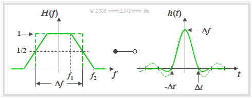
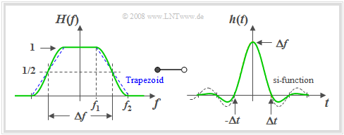
Die folgende Grafik zeigt für den Rolloff–Faktor $r_f = 0.5 \ \Rightarrow \ f_2 = 3f_1$ links den Frequenzgang $H(f)$ und rechts die Impulsantwort
- $$h(t) = \Delta f \cdot {\rm si}(\pi \cdot \Delta f \cdot t )\cdot {\rm si}(\pi \cdot r_{\hspace{-0.05cm}f} \cdot \Delta f \cdot t )\hspace{0.7cm}{\rm{mit}}\hspace{0.7cm}{\rm si}(x) = {\sin(x)}/{x}.$$
Der $\rm si$–Zeitverlauf des rechteckförmigen Tiefpasses mit gleicher äquivalenter Bandbreite ist zum Vergleich gestrichelt eingezeichnet.
Die Grafik sowie obige Gleichungen erlauben folgende Aussagen:
- Die Trapezform entsteht zum Beispiel durch die Faltung zweier Rechtecke der Breiten $Δf$ und $r_f \cdot Δf$.
- Entsprechend dem Faltungssatz ist somit die Impulsantwort das Produkt zweier $\rm si$–Funktionen mit den Argumenten $π · Δf · t$ und $π · r_{\hspace{-0.05cm}f} · Δf · t$.
- Die erste $\rm si$–Funktion ist für alle Werte von $r_{\hspace{-0.05cm}f}$ Bestandteil der Gleichung für $h(t)$ und führt stets zu äquivalenten Nulldurchgängen im Abstand $1/Δf$.
- Für $0 \lt r_{\hspace{-0.05cm}f} \lt 1$ gibt es weitere Nullstellen bei Vielfachen von $Δt/r_{\hspace{-0.05cm}f}$.
- Der asymptotische Abfall der Impulsantwort $h(t)$ erfolgt um so schneller, je größer $r_{\hspace{-0.05cm}f}$ ist, das heißt bei gegebenem $Δf$ mit flacherer Flanke.
- Der schnellstmögliche Abfall ergibt sich beim Dreiecktiefpass ⇒ $r_{\hspace{-0.05cm}f} = 1$, $f_1 = 0$, $f_2 = Δf$. Für diesen gilt im Frequenz– und Zeitbereich:
- $$H(f) = \left\{ \begin{array}{c} \hspace{0.25cm} \frac{{\rm \Delta}f -|f|}{{\rm \Delta}f} \\ \hspace{0.25cm} 0 \\ \end{array} \right.\quad \quad \begin{array}{*{10}c} {\rm{f\ddot{u}r}} \\ {\rm{f\ddot{u}r}} \\ \end{array}\begin{array}{*{20}c} {\hspace{1cm} \left| \hspace{0.005cm}f\hspace{0.05cm} \right| \le {\rm \Delta}f ,} \\ {\hspace{1cm}\left|\hspace{0.005cm} f \hspace{0.05cm} \right| \ge {\rm \Delta}f } \\ \end{array}, \hspace{1cm} h(t) = \Delta f \cdot {\rm si}^2(\pi \cdot \Delta f \cdot t )\hspace{0.4cm}{\rm{mit}}\hspace{0.4cm}{\rm si}(x) = \frac{\sin(x)}{x}.$$
Cosinus-Rolloff-Tiefpass
Ebenso wie der Trapez–Tiefpass wird dieser Tiefpass durch zwei Parameter beschrieben, nämlich durch
- die äquivalente Bandbreite $Δf$ und
- den Rolloff–Faktor $r_{\hspace{-0.05cm}f}$.
Dessen Wertebereich liegt zwischen $r_{\hspace{-0.05cm}f} = 0$ (Rechtecktiefpass) und $r_{\hspace{-0.05cm}f} = 1$ (Cosinus–Quadrat–Tiefpass).
$\text{Definition:}$ Mit den Eckfrequenzen $f_1 = Δf · (1 – r_{\hspace{-0.05cm}f})$ und $f_2 = Δf · (1 + r_{\hspace{-0.05cm}f})$ lautet der Frequenzgang des Cosinus–Rolloff–Tiefpasses:
- $$H(f) = \left\{ \begin{array}{l} \hspace{0.25cm}1 \\ \cos \left( \frac{ \vert f \vert - f_1}{f_2 -f_1}\frac{\pi}{2}\right) \\ \hspace{0.25cm} 0 \\ \end{array} \right.\quad \quad \begin{array}{*{10}c} \text{für} \\ \text{für} \\ \text{für} \\ \end{array}\begin{array}{*{20}c} {\hspace{0.94cm}\vert \hspace{0.005cm} f\hspace{0.05cm} \vert < f_1,} \\ {f_1 \le \vert \hspace{0.005cm} f\hspace{0.05cm} \vert \le f_2,} \\ {\hspace{0.94cm}\vert \hspace{0.005cm} f\hspace{0.05cm} \vert> f_2.} \\ \end{array}$$
Die Grafik zeigt links $H(f)$ sowie rechts die Impulsantwort
- $$h(t) = \Delta f \hspace{-0.05cm}\cdot\hspace{-0.05cm} {\rm si}(\pi \hspace{-0.05cm}\cdot\hspace{-0.05cm} \Delta f \hspace{-0.05cm}\cdot\hspace{-0.05cm} t )\hspace{-0.05cm}\cdot\hspace{-0.05cm} \frac {\cos(\pi \cdot r_{\hspace{-0.05cm}f} \cdot \Delta f \cdot t )}{1 - (2 \cdot r_f \cdot \Delta f \cdot t)^2}.$$
Für diese Grafiken wurde der Rolloff–Faktor $r_{\hspace{-0.05cm}f} = 0.5$ verwendet, das heißt, es gilt $f_2 = 3 \cdot f_1$.
Gestrichelt sind zum Vergleich eingezeichnet:
- im Frequenzbereich der Trapeztiefpass und
- im Zeitbereich die $\rm si$–Funktion.
Es ist zu beachten:
- Die $\rm si$–Funktion ist nicht die Fourierrücktransformierte des links blau eingezeichneten Trapeztiefpasses.
- Sie beschreibt vielmehr den (nicht dargestellten) idealen, rechteckförmigen Tiefpass im Zeitbereich.
Anhand dieser Grafik und den obigen Gleichungen sind folgende Aussagen möglich:
- Die Impulsantwort $h(t)$ des Cosinus–Rolloff–Tiefpasses hat bei allen Vielfachen von $Δt = 1/Δf$ Nullstellen, die auf die im rechten Bild gestrichelt eingezeichnete si–Funktion zurückzuführen sind.
- Der letzte Term in der $h(t)$–Gleichung führt zu weiteren Nullstellen bei Vielfachen von $Δt/r_f$. Ist $1/r_f$ ganzzahlig wie in obiger Grafik $(1/r_f = 2)$, so fallen diese neuen Nullstellen mit den anderen Nullstellen zusammen, sind also nicht erkennbar.
- Je größer der Rolloff-Faktor $r_f$ ist und je flacher damit der Flankenabfall erfolgt, desto günstiger ist im Allgemeinen das Einschwingverhalten des Cosinus-Rolloff-Tiefpasses.
- Der Cosinus–Rolloff–Tiefpass zeigt meist ein besseres asymptotisches Einschwingverhalten als der Trapez–Tiefpass mit gleichem $r_f$, obwohl dieser zumindest bei $Δf/2$ eine flachere Flanke aufweist.
- Dies lässt darauf schließen, dass das Einschwingverhalten nicht nur durch Unstetigkeitsstellen (wie beim Rechteck), sondern auch durch Knickpunkte wie beim Trapez–Tiefpass beeinträchtigt wird.
$\text{Definition:}$ Als Sonderfall ergibt sich mit $f_1 = 0$, $f_2 = Δf$ ⇒ $r_f = 1$ der Cosinus–Quadrat–Tiefpass, dessen Impulsantwort auch wie folgt dargestellt werden kann:
- $$h(t) = \frac{1}{ \Delta t}\cdot{\rm si}(\pi \frac{t}{ \Delta t}) \cdot \left[ {\rm si}(\pi \frac{t}{ \Delta t} + 0.5) - {\rm si}(\pi \frac{t}{ \Delta t} - 0.5) \right].$$
- Diese Funktion hat Nullstellen bei $t/Δt = ±1, ±1.5, ±2, ±2.5$ usw., nicht jedoch bei $t/Δt = ±0.5$.
- Der Cosinus–Quadrat–Tiefpass erfüllt als einziger Tiefpass beide Nyquistkriterien ⇒ siehe Buch Digital Signal Transmission.
Herleitung systemtheoretischer Hochpassfunktionen
Bisher wurden in diesem Kapitel fünf häufig verwendete systemtheoretische Tiefpassfunktionen betrachtet. Für jede einzelne Tiefpassfunktion lässt sich auch eine äquivalente Hochpassfunktion angeben.
$\text{Definition:}$ Ist $H_{\rm TP}(f)$ eine systemtheoretische TP–Funktion mit $H_{\rm TP}(f = 0) = 1$, so ist die äquivalente Hochpassfunktion:
- $$H_{\rm HP}(f) = 1 - H_{\rm TP}(f).$$
Damit lauten die Beschreibungsgrößen im Zeitbereich:
- $$h_{\rm HP}(t) = \delta (t) - h_{\rm TP}(t),\hspace{1cm} \sigma_{\rm HP}(t) = \gamma (t) - \sigma_{\rm TP}(t). $$
Hierbei bezeichnen:
- $h_{\rm HP}(t)$ und $h_{\rm TP}(t)$ die Impulsantworten von Hoch– und Tiefpass,
- $σ_{\rm HP}(t)$ und $σ_{\rm TP}(t)$ die dazugehörigen Sprungantworten,
- $γ(t)$ die Sprungfunktion als Ergebnis der Integration über die Diracfunktion $δ(t)$.
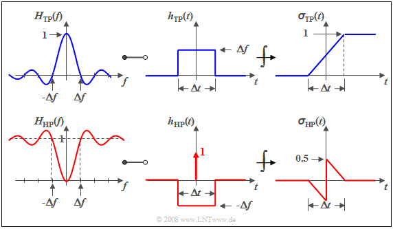
$\text{Beispiel 1:}$ Wir betrachten den Spalttiefpass, der sich durch einen $\rm si$–förmigen Frequenzgang, eine rechteckförmige Impulsantwort und eine linear ansteigende Sprungantwort auszeichnet. Diese sind in der nachfolgenden Grafik dargestellt.
Die untere Skizze zeigt die entsprechenden Hochpassfunktionen.
Man erkennt, dass
- $H_{\rm HP}(f = 0)$ immer den Wert $0$ besitzt, wenn $H_{\rm TP}(f = 0) = 1$ ist,
- demzufolge das Integral über $h_{\rm HP}(t)$ ebenfalls Null ergeben muss, und
- auch die Sprungantwort $σ_{\rm HP}(t)$ gegen den Endwert Null tendiert.
Aufgaben zum Kapitel
Aufgabe 1.5: Idealer rechteckförmiger Tiefpass
Aufgabe 1.5Z: si-förmige Impulsantwort
Aufgabe 1.6: Rechtförmeckige Impulsantwort
Aufgabe 1.6Z: Interpretation der Übertragungsfunktion
Aufgabe 1.7: Nahezu kausaler Gaußtiefpass
Aufgabe 1.8: Variable Flankensteilheit
Aufgabe 1.8Z: Cosinus-Quadrat-Tiefpass
