Difference between revisions of "Modulation Methods/OFDM for 4G Networks"
| Line 14: | Line 14: | ||
have replaced them. | have replaced them. | ||
| − | * | + | *Another name often used synonymously with "4G" is [[Mobile_Communications/General_Information_on_the_LTE_Mobile_Communications_Standard|$\rm LTE$]] (''Long Term Evolution''). Like [https://en.wikipedia.org/wiki/WiMAX WiMAX] (''Worldwide Interoperability for Microwave Access''), LTE uses [https://en.wikipedia.org/wiki/Orthogonal_frequency-division_multiplexing $\rm OFDMA$] (''Orthogonal Frequency Division Multiple Access'') as its multiple access method. |
| − | * | + | *The main difference between a pure $\rm multiplexing \; method$ $($TDM, FDM, CDM, OFDM$)$ and a $\rm multiple \; access \; method$ $($TDMA, FDMA, CDMA, OFDMA$)$ is the user separation realized by resource allocation. In the case of OFDMA, this means that not only time slots (TDMA) or spreading codes (CDMA) are allocated to the individual subscribers, but also different and "preferably" orthogonal subcarriers. |
| − | * | + | *The realization of a suitable allocation mechanism is a non-trivial problem which can only be dealt with very superficially here. It makes sense that a method is not limited to one (physical) layer, but works across layers. The term "layer" is to be understood here in the sense of the [https://en.wikipedia.org/wiki/OSI_model OSI reference model]. |
| − | * | + | *This is also necessitated by the changing requirements of a mobile communications network. Whereas '''connection-oriented''' services such as voice telephony were in the foreground at the beginning of mobile communications, today '''packet-oriented''' applications such as ''Voice over IP'' (VoIP), ''video telephony'' or ''mobile data services'' represent the main traffic load and are the cause of the increased demand on the available data rates. |
| − | == | + | ==Some characteristics of mobile radio systems== |
<br> | <br> | ||
| − | + | First of all, the special features of the mobile radio channel will be discussed very briefly. The figure shows a typical mobile radio scenario. More detailed information on this subject can be found in the book [[Mobile Communications]]. | |
| − | [[File:P_ID1649__Mod_T_5_7_S2_1_ganz_neu.png |right|frame| | + | [[File:P_ID1649__Mod_T_5_7_S2_1_ganz_neu.png |right|frame| Characteristics of the mobile communications channel '''KORREKTUR''': direct path]] |
| − | + | The main characteristics of the mobile communications channel are: | |
| − | * | + | *the distance-dependent attenuation (''Path Loss''), |
| − | * | + | *refraction, scattering and reflection effects and thus multipath propagation, |
| − | * | + | *possible shadowing by mountains, trees and houses, |
| − | * | + | *the Doppler effect due to the relative speed between transmitter and receiver. |
| − | + | Regarding "attenuation" one distinguishes | |
| − | * | + | *between ''time-dependent attenuation'' ( '' Time Selective Fading'') |
| − | * | + | *and ''frequency-dependent attenuation'' ( '' Frequency Selective Fading''). |
<br clear=all> | <br clear=all> | ||
| − | [[File:P_ID1650__Mod_T_5_7_S2_2_neu.png |left|frame| | + | [[File:P_ID1650__Mod_T_5_7_S2_2_neu.png |left|frame| Description of time-dependent and frequency-dependent attenuation '''KORREKTUR''': time-dependent attenuation, frequency-dependent attenuation ...]] |
| − | <br> | + | <br>The table above shows the respective descriptive quantities. Please note: The coherence bandwidth $f_{\rm coh}$ is not the reciprocal of the coherence time $T_{\rm coh}$, although one might assume this due to comparable naming. |
| − | * $f_{\rm coh}$ | + | * $f_{\rm coh}$ is a parameter for the frequency-dependent attenuation and results as the reciprocal of the [https://en.wikipedia.org/wiki/Delay_spread delay spread]. |
| − | * $T_{\rm coh}$ | + | * $T_{\rm coh}$ on the other hand, describes the time-dependent attenuation and is the reciprocal of the [https://en.wikipedia.org/wiki/Fading Doppler spread]. |
<br clear=all> | <br clear=all> | ||
| − | == | + | ==Determination of some OFDM parameters== |
<br> | <br> | ||
| − | + | Now we will try to adapt the OFDM system to the channel in such a way that neither time nor frequency dependent fading occurs. For this, the following must apply: | |
| − | * | + | *Time-dependent fading is avoided (i.e.: the channel is time-invariant) if the frame duration (''Time of Interest'') $T_{\rm R} = T + T_{\rm G})$ is significantly smaller than the coherence time $T_{\rm coh}$. |
| − | * | + | *Frequency selective fading (within a subcarrier) is avoided if the bandwidth of all carriers $(≈ f_0)$ is significantly smaller than the coherence bandwidth $f_{\rm coh}$: |
:$$f_0 = {1}/{T} \ll f_{{\rm{coh}}} = {1}/{{T_{\rm{D}} }} \approx {1}/{{T_{\rm{G}} }} | :$$f_0 = {1}/{T} \ll f_{{\rm{coh}}} = {1}/{{T_{\rm{D}} }} \approx {1}/{{T_{\rm{G}} }} | ||
| − | \hspace{1.0cm}({\rm z.B.\hspace{0.12cm} f\ddot{u}r }\hspace{0.15cm} \tau_{\rm min}= 0,\hspace{0.12cm}\tau_{\rm max}= T_{\rm G}\hspace{0.12cm}{\rm | + | \hspace{1.0cm}({\rm z.B.\hspace{0.12cm} f\ddot{u}r }\hspace{0.15cm} \tau_{\rm min}= 0,\hspace{0.12cm}\tau_{\rm max}= T_{\rm G}\hspace{0.12cm}{\rm applies}).$$ |
| − | * | + | *Both requirements can be summarized by the following inequality with respect to the symbol duration $T$: |
:$$T_{\rm{G}} \ll T \ll T_{{\rm{coh}}} - T_{\rm{G}}.$$ | :$$T_{\rm{G}} \ll T \ll T_{{\rm{coh}}} - T_{\rm{G}}.$$ | ||
| − | * | + | *However, the two requirements cannot be satisfied simultaneously: A larger $T$ decreases the frequency selectivity, but at the same time makes the transmission more susceptible to Doppler spreading $($smaller ratio $T_{\rm coh}/T)$. |
{{GraueBox|TEXT= | {{GraueBox|TEXT= | ||
| − | $\text{ | + | $\text{Example 1:}$ Assuming a given coherence time $T_{\rm coh}$ and maximum delay $τ_{\rm max}$ through the channel, one could proceed as follows: |
| − | * | + | *Determination of the preliminary guard interval to ${T_{\rm G} }' ≥ τ_{\rm max}$, |
| − | * | + | *Calculating the upper and lower bounds: ${T_{\rm G} }' \ll T \ll T_{\rm coh} – {T_{\rm G} }'$, |
| − | * | + | *Calculating the optimal symbol duration as a geometric mean: |
:$$T_{\rm opt} = \sqrt { {T_{\rm G} }' \cdot (T_{\rm coh} - {T_{\rm G} }') }.$$ | :$$T_{\rm opt} = \sqrt { {T_{\rm G} }' \cdot (T_{\rm coh} - {T_{\rm G} }') }.$$ | ||
| − | + | The required number $N_{\rm use}$ of subcarriers - and thus the minimum FFT support number - is obtained from this together with the data rate $R$ and the number $M$ of signal space points of the mapping used after rounding up: | |
| − | :$$N_{ {\rm{ | + | :$$N_{ {\rm{use} } } = \left\lceil {\frac{ {R \cdot (T + {T_{\rm G} }') } } { { {\rm{log}_2}(M)} } } \right\rceil \hspace{0.3cm}\Rightarrow \hspace{0.3cm} |
| − | N_{ {\rm{FFT} } } = 2^{\left\lceil { {\rm{log}_2} (N_{ {\rm{ | + | N_{ {\rm{FFT} } } = 2^{\left\lceil { {\rm{log}_2} (N_{ {\rm{use} } } )} \right\rceil }.$$ |
| − | + | The value $N_{\rm FFT}$ takes into account that the number of interpolation points of the FFT must be a power of two. The unused carriers due to the FFT adjustment are used as an additional guard band at the edges of the spectrum. | |
| − | + | The resulting guard interval must now be adjusted to the new parameters: | |
| − | :$$T_{\rm{G} } = N_{\rm{G} } \cdot \frac{{T_{{\rm{opt} } } } } { {N_{ {\rm{FFT} } } }} \quad {\rm{ | + | :$$T_{\rm{G} } = N_{\rm{G} } \cdot \frac{{T_{{\rm{opt} } } } } { {N_{ {\rm{FFT} } } }} \quad {\rm{with}} |
\quad N_{\rm{G} } = \left\lceil {\frac{ { {T_{\rm G} }' } } { {T_{ {\rm{opt} } } } } \cdot N_{ {\rm{FFT} } } } \right\rceil.$$ | \quad N_{\rm{G} } = \left\lceil {\frac{ { {T_{\rm G} }' } } { {T_{ {\rm{opt} } } } } \cdot N_{ {\rm{FFT} } } } \right\rceil.$$ | ||
| − | + | The frame duration is given by $T_{\rm R} = T + T_{\rm G}$ and the total number of samples in a frame is given by $N_{\rm total} = N_{\rm FFT} + N_{\rm G}$. Finally, the number $N_{\rm use}$ of the useful carriers must be calculated again with the above equation. }} | |
| − | == | + | ==Resource management in 4G networks== |
| − | [[File: P_ID1652__Mod_T_5_7_S4a_ganz_neu.png |right|frame| Multi- | + | [[File: P_ID1652__Mod_T_5_7_S4a_ganz_neu.png |right|frame| Multi-user diversity gain from [Vie17]<ref>Viering, I.: ''System Aspects in Communications''. Vorlesungsmanuskript, Lehrstuhl für Nachrichtentechnik, TU München, 2017.</ref>. <br>We thank Ingo Viering for permission to use the diagram.]] |
<br> | <br> | ||
| − | + | A design parameter not considered so far is the choice of the respective modulation scheme of the individual subcarriers, which has a decisive influence on the error probability during transmission. | |
| − | + | In principle, it can be said that the robustness decreases with increasing ${\rm log_2}(M)$, since this reduces the spacing of the possible signal space points. | |
| − | + | However, a large symbol range $M$ is the prerequisite for the desired high data rates, which is only possible in good channel states. The characteristics of the channel often differ greatly for the participants and change over time. | |
| − | + | The aim of a suitable '''scheduling procedure''' is now, | |
| − | * | + | *transmit only when the channel is good and |
| − | *in | + | *to serve other subscribers during the dips in attenuation. |
| − | + | The gain in system throughput that can be achieved in this way is often referred to as [https://en.wikipedia.org/wiki/Diversity_scheme multi-user diversity gain]. | |
| − | + | The diagram above shows the procedure. The blue line represents the desired ''riding on the peaks'' for the case of eight participants (eight fading processes). | |
| − | [[File:P_ID1653__Mod_T_5_7_S5_neu.png |right|frame| Cross-Layer | + | [[File:P_ID1653__Mod_T_5_7_S5_neu.png |right|frame| Cross-Layer Scheduler '''KORREKTUR''': higher layers ...]] |
| − | <br> | + | <br>When implementing a channel-adaptive scheduler, however, information from higher layers should also be included, since long waiting times (large delays) must be avoided depending on the ''Quality of Service'' $\rm (QoS)$ requirements and traffic type. The diagram on the right shows a schematic representation of such a (''cross–layer approach''). |
| − | * | + | *The scheduler is located in the MAC layer (''Medium Access Control Layer'') and communicates with the other (not necessarily neighboring) layers. It should be noted that this approach contradicts the modularity principle envisaged in the OSI model. |
| − | * | + | *A similar approach has already been implemented as part of the extension of the UMTS network to include the [[Examples_of_Communication_Systems/Weiterentwicklungen_von_UMTS#High.E2.80.93Speed_Downlink_Packet_Access|$\rm HSDPA$]] (''High Speed Downlink Packet Access'') standard, which has increased the maximum data rate in the 3G network (downstream) from $\text{384 kbit/s}$ to a theoretical $\text{ 14.4 Mbit/s}$. |
| − | + | This section was only intended to provide a rough outlook on possible future mobile communications networks. It should be noted that the improved adaptivity required for very high data rates is only made possible by the use of a multi-carrier system such as OFDM/OFDMA. | |
| − | == | + | ==Exercises for the chapter== |
<br> | <br> | ||
| − | [[Aufgaben: | + | [[Aufgaben:Exercise_5.9:_Selection_of_OFDM_Parameters|Exercise 5.9: Selection of OFDM Parameters]] |
| − | == | + | ==References== |
{{Display}} | {{Display}} | ||
Revision as of 16:20, 29 December 2021
Contents
Multiplexing vs. multiple access methods
As a first example, let's now take a look at the fourth-generation $\rm (4G)$ mobile communications networks, which are the successors to the earlier mobile communications networks based on
- $\rm TDMA/FDMA$, see GSM (Global System for Mobile Communications), and
- $\rm CDMA$, see UMTS (Universal Mobile Telecommunications System)
have replaced them.
- Another name often used synonymously with "4G" is $\rm LTE$ (Long Term Evolution). Like WiMAX (Worldwide Interoperability for Microwave Access), LTE uses $\rm OFDMA$ (Orthogonal Frequency Division Multiple Access) as its multiple access method.
- The main difference between a pure $\rm multiplexing \; method$ $($TDM, FDM, CDM, OFDM$)$ and a $\rm multiple \; access \; method$ $($TDMA, FDMA, CDMA, OFDMA$)$ is the user separation realized by resource allocation. In the case of OFDMA, this means that not only time slots (TDMA) or spreading codes (CDMA) are allocated to the individual subscribers, but also different and "preferably" orthogonal subcarriers.
- The realization of a suitable allocation mechanism is a non-trivial problem which can only be dealt with very superficially here. It makes sense that a method is not limited to one (physical) layer, but works across layers. The term "layer" is to be understood here in the sense of the OSI reference model.
- This is also necessitated by the changing requirements of a mobile communications network. Whereas connection-oriented services such as voice telephony were in the foreground at the beginning of mobile communications, today packet-oriented applications such as Voice over IP (VoIP), video telephony or mobile data services represent the main traffic load and are the cause of the increased demand on the available data rates.
Some characteristics of mobile radio systems
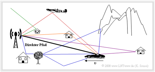
First of all, the special features of the mobile radio channel will be discussed very briefly. The figure shows a typical mobile radio scenario. More detailed information on this subject can be found in the book Mobile Communications.
The main characteristics of the mobile communications channel are:
- the distance-dependent attenuation (Path Loss),
- refraction, scattering and reflection effects and thus multipath propagation,
- possible shadowing by mountains, trees and houses,
- the Doppler effect due to the relative speed between transmitter and receiver.
Regarding "attenuation" one distinguishes
- between time-dependent attenuation ( Time Selective Fading)
- and frequency-dependent attenuation ( Frequency Selective Fading).
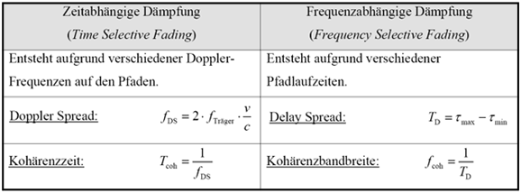
The table above shows the respective descriptive quantities. Please note: The coherence bandwidth $f_{\rm coh}$ is not the reciprocal of the coherence time $T_{\rm coh}$, although one might assume this due to comparable naming.
- $f_{\rm coh}$ is a parameter for the frequency-dependent attenuation and results as the reciprocal of the delay spread.
- $T_{\rm coh}$ on the other hand, describes the time-dependent attenuation and is the reciprocal of the Doppler spread.
Determination of some OFDM parameters
Now we will try to adapt the OFDM system to the channel in such a way that neither time nor frequency dependent fading occurs. For this, the following must apply:
- Time-dependent fading is avoided (i.e.: the channel is time-invariant) if the frame duration (Time of Interest) $T_{\rm R} = T + T_{\rm G})$ is significantly smaller than the coherence time $T_{\rm coh}$.
- Frequency selective fading (within a subcarrier) is avoided if the bandwidth of all carriers $(≈ f_0)$ is significantly smaller than the coherence bandwidth $f_{\rm coh}$:
- $$f_0 = {1}/{T} \ll f_{{\rm{coh}}} = {1}/{{T_{\rm{D}} }} \approx {1}/{{T_{\rm{G}} }} \hspace{1.0cm}({\rm z.B.\hspace{0.12cm} f\ddot{u}r }\hspace{0.15cm} \tau_{\rm min}= 0,\hspace{0.12cm}\tau_{\rm max}= T_{\rm G}\hspace{0.12cm}{\rm applies}).$$
- Both requirements can be summarized by the following inequality with respect to the symbol duration $T$:
- $$T_{\rm{G}} \ll T \ll T_{{\rm{coh}}} - T_{\rm{G}}.$$
- However, the two requirements cannot be satisfied simultaneously: A larger $T$ decreases the frequency selectivity, but at the same time makes the transmission more susceptible to Doppler spreading $($smaller ratio $T_{\rm coh}/T)$.
$\text{Example 1:}$ Assuming a given coherence time $T_{\rm coh}$ and maximum delay $τ_{\rm max}$ through the channel, one could proceed as follows:
- Determination of the preliminary guard interval to ${T_{\rm G} }' ≥ τ_{\rm max}$,
- Calculating the upper and lower bounds: ${T_{\rm G} }' \ll T \ll T_{\rm coh} – {T_{\rm G} }'$,
- Calculating the optimal symbol duration as a geometric mean:
- $$T_{\rm opt} = \sqrt { {T_{\rm G} }' \cdot (T_{\rm coh} - {T_{\rm G} }') }.$$
The required number $N_{\rm use}$ of subcarriers - and thus the minimum FFT support number - is obtained from this together with the data rate $R$ and the number $M$ of signal space points of the mapping used after rounding up:
- $$N_{ {\rm{use} } } = \left\lceil {\frac{ {R \cdot (T + {T_{\rm G} }') } } { { {\rm{log}_2}(M)} } } \right\rceil \hspace{0.3cm}\Rightarrow \hspace{0.3cm} N_{ {\rm{FFT} } } = 2^{\left\lceil { {\rm{log}_2} (N_{ {\rm{use} } } )} \right\rceil }.$$
The value $N_{\rm FFT}$ takes into account that the number of interpolation points of the FFT must be a power of two. The unused carriers due to the FFT adjustment are used as an additional guard band at the edges of the spectrum.
The resulting guard interval must now be adjusted to the new parameters:
- $$T_{\rm{G} } = N_{\rm{G} } \cdot \frac{{T_{{\rm{opt} } } } } { {N_{ {\rm{FFT} } } }} \quad {\rm{with}} \quad N_{\rm{G} } = \left\lceil {\frac{ { {T_{\rm G} }' } } { {T_{ {\rm{opt} } } } } \cdot N_{ {\rm{FFT} } } } \right\rceil.$$
The frame duration is given by $T_{\rm R} = T + T_{\rm G}$ and the total number of samples in a frame is given by $N_{\rm total} = N_{\rm FFT} + N_{\rm G}$. Finally, the number $N_{\rm use}$ of the useful carriers must be calculated again with the above equation.
Resource management in 4G networks

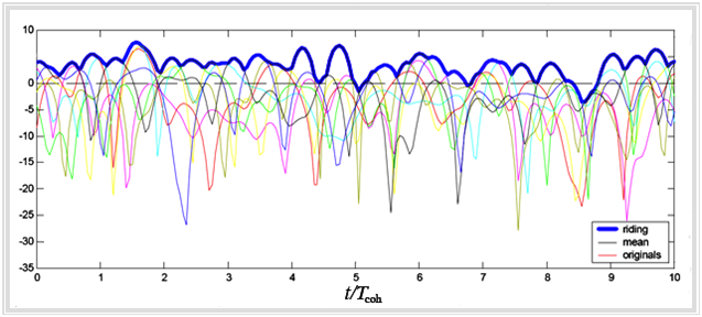
We thank Ingo Viering for permission to use the diagram.
A design parameter not considered so far is the choice of the respective modulation scheme of the individual subcarriers, which has a decisive influence on the error probability during transmission.
In principle, it can be said that the robustness decreases with increasing ${\rm log_2}(M)$, since this reduces the spacing of the possible signal space points.
However, a large symbol range $M$ is the prerequisite for the desired high data rates, which is only possible in good channel states. The characteristics of the channel often differ greatly for the participants and change over time.
The aim of a suitable scheduling procedure is now,
- transmit only when the channel is good and
- to serve other subscribers during the dips in attenuation.
The gain in system throughput that can be achieved in this way is often referred to as multi-user diversity gain.
The diagram above shows the procedure. The blue line represents the desired riding on the peaks for the case of eight participants (eight fading processes).
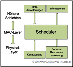
When implementing a channel-adaptive scheduler, however, information from higher layers should also be included, since long waiting times (large delays) must be avoided depending on the Quality of Service $\rm (QoS)$ requirements and traffic type. The diagram on the right shows a schematic representation of such a (cross–layer approach).
- The scheduler is located in the MAC layer (Medium Access Control Layer) and communicates with the other (not necessarily neighboring) layers. It should be noted that this approach contradicts the modularity principle envisaged in the OSI model.
- A similar approach has already been implemented as part of the extension of the UMTS network to include the $\rm HSDPA$ (High Speed Downlink Packet Access) standard, which has increased the maximum data rate in the 3G network (downstream) from $\text{384 kbit/s}$ to a theoretical $\text{ 14.4 Mbit/s}$.
This section was only intended to provide a rough outlook on possible future mobile communications networks. It should be noted that the improved adaptivity required for very high data rates is only made possible by the use of a multi-carrier system such as OFDM/OFDMA.
Exercises for the chapter
Exercise 5.9: Selection of OFDM Parameters
References
- ↑ Viering, I.: System Aspects in Communications. Vorlesungsmanuskript, Lehrstuhl für Nachrichtentechnik, TU München, 2017.


