Difference between revisions of "Modulation Methods/Objectives of Modulation and Demodulation"
m |
m |
||
| Line 134: | Line 134: | ||
*The modulated signal $s(t)$ shows that the modulator also has similar functionality in the digital transmission system as in the (above) analog transmission system.}} | *The modulated signal $s(t)$ shows that the modulator also has similar functionality in the digital transmission system as in the (above) analog transmission system.}} | ||
| − | + | Analog modulation methods currently (2005) still have a certain significance, especially for the distribution of radio and television programs, but are being increasingly displaced by corresponding digital methods in this area. Nevertheless, we will devote more space in | |
| − | + | [[Modulation_Methods|this book]] to analog methods: | |
| − | * Kapitel 2: [[Modulation_Methods/Zweiseitenband-Amplitudenmodulation| | + | * Kapitel 2: [[Modulation_Methods/Zweiseitenband-Amplitudenmodulation|Amplitude modulation and AM–Demodulation]], |
| − | * Kapitel 3: [[Modulation_Methods/Phasenmodulation_(PM)| | + | * Kapitel 3: [[Modulation_Methods/Phasenmodulation_(PM)|Angle modulation and WM–Demodulation]]. |
| Line 158: | Line 158: | ||
*the introduction of NTSC colour television (1953), | *the introduction of NTSC colour television (1953), | ||
*the introduction of PAL colour television (1967). | *the introduction of PAL colour television (1967). | ||
| + | |||
The following inventions, among others, were necessary for these developments: | The following inventions, among others, were necessary for these developments: | ||
Revision as of 22:23, 24 October 2021
Contents
- 1 # OVERVIEW OF FIRST MAIN CHAPTER #
- 2 The message transmission system under consideration
- 3 Adapting to the transmission channel and interference spectrum
- 4 Channel bundling – frequency division multiplexing
- 5 Analog vs. digital transmission systems
- 6 The historical development of analog modulation methods
- 7 Vorteile der digitalen Modulationsverfahren
- 8 Zeitmultiplexverfahren
- 9 Aufgaben zum Kapitel
# OVERVIEW OF FIRST MAIN CHAPTER #
This book deals with Modulation and Demodulation , two classical and important methods for communications engineering, which already have a very long tradition but are nevertheless constantly developing.
Before analog amplitude and angle modulation are described in detail in the following chapters, along with today's more relevant digital modulation methods, this first chapter introduces the definitions and descriptive variables which are equally valid for all systems.
This chapter deals in detail with:
- the objectives of Modulation and Demodulation,
- the differences and similarities between analog and digital modulation techniques,
- the signal-to-noise power ratio as a very general quality criterion,
- linear and non-linear distortions due to modulation/demodulation,
- degradation in the presence of stochastic interference, such as noise,
- a unified model for describing amplitude and angle modulation,
- descriptions using the analytical signal and the equivalent low–pass signal.
The message transmission system under consideration
Throughout the book "Modulation Methods", we will be base our message transmission system on the block diagram shown here.
The transmission medium (the physical transmission channel) is characterised here by its frequency response $H_{\rm K}(f)$ . We will consider:
- electrical lines (coaxial cable, twisted pair, etc.),
- optical fibres (multimode or single mode),
- radio connections (directional radio, satellite radio, mobile radio, etc.).
Further considerations:
- Let the source signal $q(t)$ be an analog signal, for example, speech, music or the (analog) output of a camera. Let the corresponding spectrum $Q(f)$ lie in the frequency range $|f| ≤ B_{\rm LF}$ , where the subscript stands for "low frequency".
- The middle block in the above figure also includes interference (interference, crosstalk from other users, impulse interference from power lines, etc.) and noise sources such as thermal and semiconductor noise. These are captured by the interference power density spectrum ${\it Φ}_n(f)$.
- The task of such a message transmission system is to transmit the message or information contained in the source signal $q(t)$ – note the different meaning of these quantities – to the spatially distant sink, with the proviso that the sink signal $v(t)$ differs "as little as possible" from $q(t)$.
- A common problem is that the channel is unsuitable for direct transmission of the source signal $q(t)$ because it contains "unfavourable frequencies". For example, a music signal with frequencies up to about $\text{15 kHz}$ cannot be transmitted directly by radio, since radio propagation is only possible from around $\text{100 kHz}$.
- The only solution here is a signal conversion at the transmitter known as modulation. The output signal of the modulator will be uniformly referred to as the transmission signal $s(t)$ in the following. This is generally at higher frequencies than the source signal $q(t)$.
- Demodulation is the signal reset at the receiver to recover the low frequency sink signal $v(t) ≈ q(t)$ from the high frequency received signal $r(t)$ . With real channels, the desired result $v(t) \equiv q(t)$ is not possible due to the noise $n(t)$ that is always present.
Adapting to the transmission channel and interference spectrum
The primary task of modulation (in the sense meant here) is adding a higher frequency carrier signal with carrier frequency $f_{\rm T}$ to shift the message signal to a different frequency position,
- with a more favourable frequency response $H_{\rm K}(f)$ and/or
- with a more favourable interference power density spectrum ${\it Φ}_n(f)$.
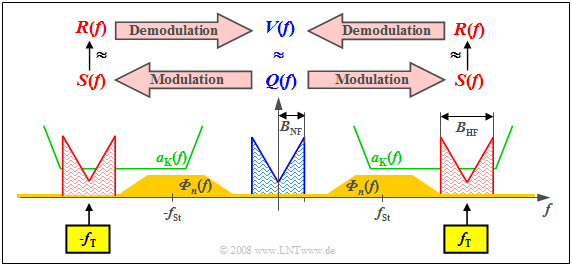
$\text{Example 1:}$ The graph shows the low-frequency spectrum $Q(f)$ with bandwidth $B_{\rm NF}$ in blue. The attenuation curve $a_{\rm K}(f) = \ –\ln \ \vert H_{\rm K}(f) \vert $ of the channel is plotted in green, which here shows favourable characteristics with constant low attenuation in a sufficiently large frequency range.
In yellow, you can see the interference power density spectrum ${\it Φ}_n(f)$, which does not disappear throughout the frequency range due to thermal noise and, in our constructed example, takes on particularly large values around frequency $f_{\rm St}$ due to external interference.
These boundary conditions make clear:
- One must select the carrier frequency $f_{\rm T}$ approximately as drawn so that $S(f)$ can be transmitted in the best possible way with respect to distortion and interference/noise. This results in a frequency band of sufficient quality with width $B_{\rm HF} = 2 · B_{\rm NF}$.
- This shift of the source signal spectrum $Q(f)$ by the carrier frequency $f_{\rm T}$ to the right – and also by the same distance to the left due to the system-theoretical approach of bilateral frequencies – represents modulation.
- Demodulation, on the other hand, is signal conversion in the opposite direction. Starting from the received spectrum $R(f)$, which differs at least slightly from the transmitted spectrum $S(f)$ due to attenuation and noise, one arrives at the spectral function $V(f) ≈ Q(f)$.
Further reasons for modulation/demodulation are given in the following sections.
Channel bundling – frequency division multiplexing
Another advantage of modulation with a harmonic oscillation as a carrier signal is that a single transmission channel of sufficient bandwidth can be used by several signals simultaneously. One then speaks of
- Frequency Division Multiplexing (FDM)
- or Frequency Division Multiple Access (FDMA).
The diagram illustrates the situation. $K$ message signals are to be transmitted simultaneously via a physical channel of appropriate bandwidth. The subchannels are marked here with $T_1$, ... , $T_K$ . One proceeds as follows:
- One modulates the source signals $q_1(t)$, $q_2(t)$, ... , $q_K(t)$ of users with different carrier frequencies $f_1$, $f_2$, ... , $f_K$.
- One combines the transmission signals $s_1(t)$, $s_2(t)$, ... , $s_K(t)$ to form a total signal 𝑠(𝑡), enabling multiple use of the transmission set-up.
- To demodulate the source signal $q_k(t)$ , one uses the special carrier frequency $f_k$. Subsequent filtering achieves $v_k(t) = q_k(t)$ (but only with negligible noise interference). This process is called channel separation.
$\text{Example 2:}$ Frequency division multiplexing has been used for many decades in analog TV and radio transmission.
- This allows a sufficient number of programs to be accommodated, such as in the UHF band $($frequencies between $\text{470 MHz}$ and $\text{850 MHz)}$ , where more than forty TV programs have a channel spacing of $\text{8 MHz}$.
- However, since around 2004, analog TV transmission in this frequency band has been increasingly displaced by the new digital video standard Digital Video Broadcast – Terrestrial (DVB–T), which also uses FDMA.
$\text{Example 3:}$
- In optical transmission technology, this FDMA method is called wave-length division multiplex (WDM).
- At present (2005), $160$ digital signals at $\text{10 Gbit/s}$ each can be transmitted simultaneously via a single optical fibre ⇒ Total bit rate: $\text{1.6 Tbit/s}$.
Analog vs. digital transmission systems
For the entire book "Modulation Methods", it is assumed that the source signal $q(t)$ and the sink signal $v(t)$ are both analog signals.
- Thus, they can be continuous in both time and value.
- However, this does not yet determine whether the actual transmission is analog or digital.
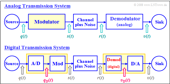
The two block diagrams illustrate the main differences between an analog and a digital message transmission system.
It becomes clear that:
- In analog modulation, the modulating signal $q(t)$ is always an analog signal and thus both continuous in value and in time.
- In contrast, in digital modulation, the modulator's input signal $q_{\rm D}(t)$ is always digital, thus both discrete in value and discrete in time.
- When digitally modulating an analog audio or video signal $q(t)$ , it must first be A/D converted: $q(t) \ \rightarrow \ q_{\rm D}(t)$.
- This is referred to as Pulse-code modulation. This requires the following actions on the transmission side: Sampling – Quantisation – (PCM–)Encoding.
- Functionally, the modulator of the digital system $\rm (Mod)$ does not differ from the modulator of the analog transmission system.
- However, the two demodulators differ in principle: the upper one provides the analog signal $v(t)$, the lower one provides the digital signal $v_{\rm D}(t)$.
- After the digital transmission of an analog signal - such as audio or video - a D/A conversion must therefore still take place.
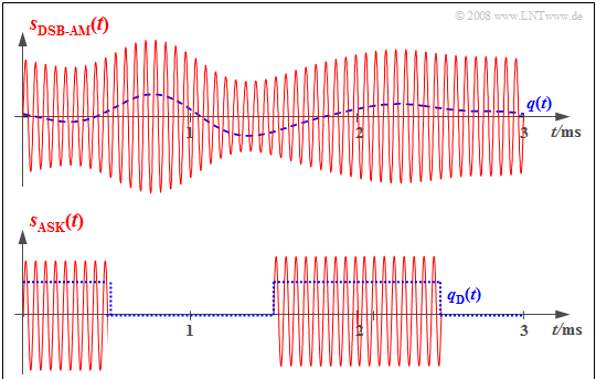
$\text{Example 4:}$ The two graphs show the respective input signals (each in blue dashed lines) and output signals (solid red) of the modulator for an analog and a digital transmission system.
- In the analog transmission system (above), the information about the analog source signal $q(t)$ is directly in the amplitude (envelope) of the modulated signal $s(t)$. This is the analog modulation method Double-sideband amplitude modulation with carrier.
- The bottom graph refers to Amplitude Shift Keying (ASK), the digital variant of amplitude modulation. Here, the modulator input signal $q_{\rm D}(t)$ is digital and derived from the analog source signal $q(t)$ by sampling, quantisation, and PCM encoding.
- The modulated signal $s(t)$ shows that the modulator also has similar functionality in the digital transmission system as in the (above) analog transmission system.
Analog modulation methods currently (2005) still have a certain significance, especially for the distribution of radio and television programs, but are being increasingly displaced by corresponding digital methods in this area. Nevertheless, we will devote more space in
this book to analog methods:
- Kapitel 2: Amplitude modulation and AM–Demodulation,
- Kapitel 3: Angle modulation and WM–Demodulation.
$\text{Die Gründe hierfür sind:}$
- Aufgrund der hohen Kosten bei der Umrüstung bestehender sowie der Einführung neuer Systeme werden auch für die Analogsysteme noch längere Laufzeiten prognostiziert.
- Viele Komponenten eines Analogsystems werden ebenso bei den digitalen Modulationsverfahren benötigt, zum Beispiel der in beiden Varianten verwendete Synchrondemodulator.
- Die typische Vorgehensweise bei der Untersuchung nachrichtentechnischer Aspekte lässt sich bei Analogsystemen umfassender – und oft auch verständlicher – erklären als bei Digitalsystemen.
The historical development of analog modulation methods
The following dates represent milestones for the development of analog modulation methods using carrier frequencies:
- the introduction of regular broadcasting service (1923),
- the start of carrier-frequency telephony (1923),
- the introduction of regular television service (1935),
- the first satellite transmission (1945),
- the introduction of NTSC colour television (1953),
- the introduction of PAL colour television (1967).
The following inventions, among others, were necessary for these developments:
- 1861: the electrical transmission of speech ⇒ Philip Reis,
- 1876: the first commercially usable telephone ⇒ Alexander Graham Bell,
- 1884: the development of line scanning ⇒ Paul Julius Gottlieb Nipkow,
- 1887: the discovery of electromagnetic waves ⇒ Heinrich Hertz,
- 1906: the invention of the electron tube ⇒ Robert von Lieben and Lee de Forest,
- 1948: the invention of the transistor ⇒ William Bradford Shockley, Walter Houser Brattain and John Bardeen.
Vorteile der digitalen Modulationsverfahren
Die Vorteile der digitalen Modulationsverfahren sind vielfältig:
- Die Realisierung eines Digitalsystems kann ebenfalls digital erfolgen und die Schaltungen sind in hohem Maße integrierbar (VLSI – Very Large Scale Integration).
- Die Übertragungsqualität ist meist sehr gut, da sich (Rausch–)Störungen nur dann bemerkbar machen, wenn sie größer als ein vorgegebener Schwellenwert sind.
- Wegen der möglichen Signalregenerierung in regelmäßigen Abständen durch so genannte Regeneratoren können sehr große Entfernungen mit hinreichend guter Übertragungsqualität überbrückt werden.
- Die Datenübertragung – zum Beispiel zwischen Server und Client – bietet sich in digitaler Form an, da jedes Datensignal bereits digital ist. Analogsignale müssen vor der Übertragung digitalisiert werden.
- Durch die einheitliche Übertragung von Sprach–, Bild– und Datensignalen ist es möglich, ein gemeinsames und leistungsfähiges Netz für viele Telekommunikationsdienste aufzubauen.
- Es existieren einfache und sehr effiziente Verschlüsselungs– und Datensicherungsmechanismen für Digitalsignale, was eine wichtige Voraussetzung für sicherheitskritische Anwendungen ist.
- Bei einem Digitalsystem können – eventuell zusätzlich zu Frequenzmultiplex – auch die Vorteile von Zeitmultiplexverfahren genutzt werden, die nachfolgend beschrieben werden.
Alle in den letzten Jahren entwickelten Systeme sind digital, zum Beispiel:
- Compact Disc (CD) – digitales Speichermedium (Philips, 1982),
- Digital European Cordless Telephone (DECT) – schnurloses Telefon (1992),
- Global System for Mobile Communication (GSM) – europäisches Mobilfunksystem (1992),
- Integrated Services Digital Network (ISDN) – digitales Telefonnetz (in Europa 1993),
- Digital Audio Broadcast (DAB) – digitaler Rundfunk (2001),
- Digital Video Broadcast (DVB) – digitales Fernsehen (2002),
- Digital Subscriber Line (DSL) – schnelle Rechnerkopplung (2002),
- Universal Mobile Telephone System UMTS) – Mobilfunk der 3. Generation (2003),
- Long Term Evolution (LTE) – Mobilfunk der 4. Generation (2011).
Die Zahlen in Klammern geben jeweils die Jahreszahl des ersten Einsatzes an. Meistens hat es von der Erfindung über die Standardisierung bis hin zur Entwicklung eines einsatzfähigen Systems mehr als ein Jahrzehnt gedauert.
- In vierten Hauptkapitel dieses Buches sind die digitalen Modulationsverfahren zusammenfassend dargestellt.
- Eine detaillierte Beschreibung (Berechnung der Fehlerwahrscheinlichkeit, Aspekte der Systemoptimierung, usw.) finden Sie im Buch Digital Signal Transmission.
Zeitmultiplexverfahren
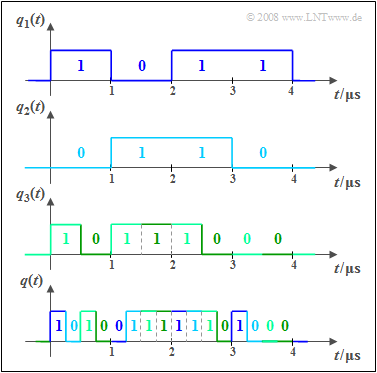
Bei einem Digitalsystem kann zur gemeinsamen Nutzung eines Übertragungskanals durch mehrere Nutzer neben Frequenzmultiplex auch die Zeitmultiplextechnik eingesetzt werden. Die Grafik soll das Prinzip an einem Beispiel verdeutlichen:
- Die Signale $q_1(t), q_2(t)$ und $q_3(t)$ sind binär und werden durch Amplitudenkoeffizienten $(0$ oder $1)$ vollständig beschrieben. Es liegt eine zeitdiskrete Signaldarstellung vor $($Symboldauer $T = 1\ \rm µ s)$.
- Für die Bitraten dieser beiden ersten Signale gilt jeweils $R_1 = R_2 = 1/T = \text{1 Mbit/s}$. Dagegen ist die Bitrate von $q_3(t)$ doppelt so groß, also $R_3 = \text{2 Mbit/s}$.
- Unten dargestellt ist das gemeinsame Zeitmultiplex–Ausgangssignal $q(t)$ mit der Gesamtbitrate $R = R_1 + R_2 + R_3 = \text{4 Mbit/s}$. Der Bezug zu den Eingangssignalen ist farblich gekennzeichnet.
- Nach der Übertragung von $q(t)$ über den physikalischen Kanal müssen die Teilsignale $v_1(t)$, ... , $v_3(t)$ beim Empfänger wieder getrennt werden. Man nennt diese Funktionseinheit den Demultiplexer.
- In der Praxis erfolgt das Multiplexen meist nicht bitweise, sondern den Teilnehmern werden in einem festen Raster Zeitschlitze zur Verfügung gestellt, in denen Bitrahmen übertragen werden.
Aufgaben zum Kapitel
Aufgabe 1.1: Multiplexing beim GSM–System


