Double-Sideband Amplitude Modulation
Contents
- 1 # OVERVIEW OF THE SECOND MAIN CHAPTER #
- 2 Description in the frequency domain
- 3 Description in the time domain
- 4 Ring modulator
- 5 AM signals and spectra with a harmonic input signal
- 6 Double-Sideband Amplitude Modulation with carrier
- 7 Describing DSB-AM with carrier using the analytical signal
- 8 Amplitude modulation with a quadratic characteristic curve
- 9 Exercises for the chapter
# OVERVIEW OF THE SECOND MAIN CHAPTER #
After some general explanations of modulation and demodulation, now a detailed description of »amplitude modulation« and the associated »demodulators«.
This chapter deals in detail with:
- the description and realization of »double-sideband amplitude modulation« $\text{(DSB–AM)}$ in frequency and time domain,
- the characteristics of a »synchronous demodulator« and the possible applications of an »envelope demodulator«,
- the similarities/differences of »single-sideband modulation» $\text{(SSB–AM)}$ compared to DSB-AM and »modified AM methods».
Description in the frequency domain
We consider the following problem: a source signal $q(t)$, whose spectrum $Q(f)$ is bandlimited to the range $\pm B_{\rm NF}$ (subscript "NF" from German "Niederfrequenz" ⇒ low frequency),
- is to be shifted to a higher frequency range where the channel frequency response $H_{\rm K}(f)$ has favorable characteristics,
- using a harmonic oscillation of frequency $f_{\rm T}$, which we will refer to as the carrier signal $z(t)$.
The diagram illustrates the task, with the following simplifying assumptions:
- The spectrum $Q(f)$ drawn here is schematic. It states that only spectral components in the range $|f| ≤ B_{\rm NF}$ are included in $q(t)$. $Q(f)$ could also be a line spectrum.
- Let the channel be ideal in a bandwidth range $B_{\rm K}$ around frequency $f_{\rm M}$, that is, let $H_{\rm K}(f) = 1$ for $|f - f_{\rm M}| ≤ B_{\rm K}/2.$ Impairments by noise are ignored for now.
- Let the carrier signal be cosine $($phase $ϕ_{\rm T} = 0)$ and have amplitude $A_{\rm T} = 1$ (without a unit). Let the carrier frequency $f_{\rm T}$ be equal to the center frequency of the transmission band.
- Thus, the spectrum of the carrier signal $z(t) = \cos(ω_{\rm T} · t)$ is
(plotted in green in the graph):
- $$Z(f) = {1}/{2} \cdot \delta (f + f_{\rm T})+{1}/{2} \cdot \delta (f - f_{\rm T})\hspace{0.05cm}.$$
Those familiar with the $\text{laws of spectral transformation}$ and in particular with the $\text{Convolution Theorem}$ can immediately give a solution for the spectrum $S(f)$ of the modulator output signal:
- $$S(f)= Z(f) \star Q(f) = 1/2 \cdot \delta (f + f_{\rm T})\star Q(f)+1/2 \cdot \delta (f - f_{\rm T})\star Q(f) = 1/2 \cdot Q (f + f_{\rm T})+ 1/2 \cdot Q(f - f_{\rm T}) \hspace{0.05cm}.$$
$\text{Please note:}$ This equation takes into account
- that the convolution of a shifted Dirac delta function $δ(x - x_0)$ with an arbitrary function $f(x)$ yields the »shifted function« $f(x - x_0)$.
The diagram displays the result. One can identify the following characteristics:
- Due to the system-theoretic approach with positive and negative frequencies, $S(f)$ is composed of two parts around $\pm f_{\rm T}$, each of which have the same shape as $Q(f)$.
- The factor $1/2$ results from the carrier amplitude $A_{\rm T} = 1$. Thus, $s(t = 0) = q(t = 0)$ and the integrals over their spectral functions $S(f)$ and $Q(f)$ must also be equal.
- The channel bandwidth $B_{\rm K}$ must be at least twice the signal bandwidth $B_{\rm NF}$, which gives the name
»Double-Sideband Amplitude Modulation« $\text{(DSB–AM)}$.
- It should be noted that $B_{\rm NF}$ and $B_{\rm K}$ are absolute and $\text{non-equivalent bandwidths}$. The latter are defined over rectangles of equal area and are denoted in our tutorial by $Δf_q$ and $Δf_{\rm K}$, resp.
- The spectral function $S(f)$ does not include any Dirac-lines at the carrier frequency $(\pm f_{\rm T})$. Therefore, this method is also referred to as "DSB-AM without carrier".
- The frequency components
- above the carrier frequency $f_{\rm T}$ are called the "upper sideband" $\rm (USB)$,
- and those below $f_{\rm T}$ are the "lower sideband" $\rm (LSB)$.
Description in the time domain
Adapting the notation and nomenclature to this problem, the convolution theorem reads:
- $$S(f) = Z(f) \star Q(f)\hspace{0.2cm}\bullet\!\!-\!\!\!-\!\!\!-\!\!\circ\, \hspace{0.2cm} s(t) = q(t) \cdot z(t) = q(t) \cdot \cos(\omega_{\rm T}\cdot t + \phi_{\rm T})\hspace{0.05cm}.$$
This result is still true if the restrictions made in the last section are removed:
- real-valued spectrum $Q(f)$,
- carrier phase $ϕ_{\rm T} = 0$.
In general, this results in a complex-valued spectrum $S(f)$.
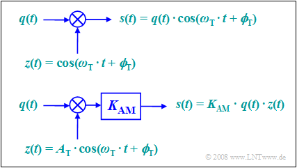
According to this equation, two models can be given for double-sideband amplitude modulation. These are to be interpreted as follows:
- The upper model directly describes the relationship given above, where the carrier $z(t) = \cos(ω_{\rm T}t + ϕ_{\rm T})$ is applied without a unit.
- The lower model is more in line with the physical condition "each signal also has a unit". If $q(t)$ and $z(t)$ are voltages, the model still needs to provide a scaling with the modulator constant $K_{\rm AM}$ with unit $\rm 1/V$, so that the output signal $s(t)$ also represents a voltage waveform.
- If we set $K_{\rm AM} = 1/A_{\rm T}$, both models are the same. In the following, we will always assume the lower, simpler model.
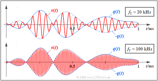
$\text{Example 1:}$ The graph shows in red the transmitted signals $s(t)$ for DSB–AM with two different carrier frequencies.
The source signal $q(t)$ with bandwidth $B_{\rm NF} = 4\text{ kHz}$, which is the same in both cases, is drawn in solid blue and the signal $-q(t)$ is dashed.
The carrier signal $z(t)$ has a cosine shape in both cases. In the upper sketch, the carrier frequency (German: "Trägersignal" ⇒ subscript "T") is $f_{\rm T} = 20\text{ kHz}$ and in the lower sketch $f_{\rm T} = 100\text{ kHz}$.
Ring modulator
One possibility to realize "double-sideband amplitude modulation with carrier suppression" is offered by a so-called »ring modulator«, also known as "double push-pull diode modulator". Below you can see the circuit on the left and a simple functional diagram on the right.
Without claiming to be complete, the principle can be stated as follows:
- Let the amplitude of the harmonic carrier oscillation $z(t)$ be much larger than the maximum value $q_{\rm max}$ of the source signal $q(t)$. Thus, all diodes are operated as switches.
- When the half-wave of the carrier is positive $(z(t) > 0)$ the two magenta diodes conduct while the light green ones block. Thus, without considering losses, it holds $s(t) = q(t)$.
- For a negative half-wave, the light green diodes conduct and the diodes in the longitudinal branches block. As can be seen on the right, $s(t) = \ – q(t)$ holds for this lower switch position.
- Due to the operation of this switch, the harmonic oscillation $z(t)$ can also be replaced by a periodic (rectangular) square wave signal with identical period duration:
- $$z_{\rm R}(t) = \left\{ \begin{array}{c} +1 \\ -1 \\ \end{array} \right.\quad \begin{array}{*{10}c} {\rm{for}} \\ {\rm{for}} \\ \end{array}\begin{array}{*{20}c} {z(t) >0,} \\ {z(t) <0.} \\ \end{array}$$
- The modulated signal $s(t)$ is then obtained as the product of the source signal $q(t)$ and this rectangular signal $z_{\rm R}(t)$, whereas in ideal DSB-AM one multiplies $q(t)$ by a cosine signal. The carrier $z(t)$ is not itself included in the signal $s(t)$. Since this is supplied via the center taps of the transformers, the induced voltages cancel out ⇒ »DSB-AM without carrier«.
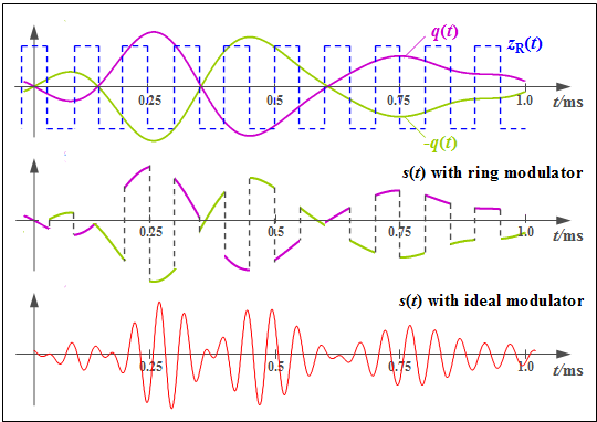
$\text{Example 2:}$ Now we will explain the operation mode of a ring modulator using exemplary signal characteristics. Let the carrier frequency be $f_{\rm T} = 10\text{ kHz}$.
- The top graph shows the signals $q(t)$ and $-q(t)$ as magenta and light green waveforms respectively. The bipolar square wave (rectangular) signal $z_{\rm R}(t)$ is shown in blue dashes, and takes the values $±1$ .
- The middle chart shows the modulated signal from the ring modulator:
- $$s_{\rm RM}(t) = q(t) · z_{\rm R}(t).$$
- For comparison, the conventional DSB-AM signal is shown in the bottom graph:
- $$s(t) = q(t) · \cos(ω_{\rm T} · t).$$
One can see significant differences, but these can be compensated for in a simple way:
- The Fourier series representation of the periodic rectangular signal $z_{\rm R}(t)$ is:
- $$z_{\rm R}(t) = \frac{4}{\pi} \cdot \cos(\omega_{\rm T}\cdot t)-\frac{4}{3\pi} \cdot \cos(3\omega_{\rm T}\cdot t) +\frac{4}{5\pi} \cdot \cos(5\omega_{\rm T}\cdot t)- \text{ ...}$$
- The associated spectral function consists of Dirac delta lines at $±f_{\rm T}, ±3f_{\rm T}, ±5f_{\rm T}$, etc. Convolution with $Q(f)$ leads to the spectrum
(the subscript stands for "ring modulator"):
- $$S_{\rm RM}(f) = \frac{2}{\pi} \cdot Q (f \pm f_{\rm T})-\frac{2}{3\pi} \cdot Q (f \pm 3f_{\rm T})+\frac{2}{5\pi} \cdot Q (f \pm 5f_{\rm T}) -\text{ ...} \hspace{0.05cm}$$
- From this, it can be seen that by appropriately band-limiting $($e.g. to $±2f_{\rm T})$ and attenuating with $π/4 ≈ 0.785$ the familiar DSB-AM spectrum can be obtained:
- $$S(f) = {1}/{2} \cdot Q (f \pm f_{\rm T})\hspace{0.05cm}.$$
Here it must be taken into account that in the above reasoning, $B_{\rm NF} \ll f_{\rm T}$ must hold.
AM signals and spectra with a harmonic input signal
Now we consider a special case which is important for testing purposes, where not only the carrier $z(t)$ is a harmonic oscillation, but also the signal $q(t)$ to be modulated:
- $$\begin{align*}q(t) & = A_{\rm N} \cdot \cos(\omega_{\rm N} \cdot t + \phi_{\rm N})\hspace{0.05cm}, \\ \\ z(t) & = \hspace{0.15cm}1 \hspace{0.13cm} \cdot \hspace{0.1cm}\cos(\omega_{\rm T} \cdot t + \phi_{\rm T})\hspace{0.05cm}.\end{align*}$$
Please note: Since we are describing modulation processes, the phase term is used with a plus sign in the above equations.
- Thus, $ϕ_{\rm N} = - 90^\circ$ represents a sinusoidal input signal $q(t)$ and $ϕ_{\rm T} = - 90^\circ$ denotes a sinusoidal carrier signal $z(t)$.
- Therefore, the equation for the modulated signal is:
- $$s(t) = q(t) \cdot z(t) = A_{\rm N} \cdot \cos(\omega_{\rm N} t + \phi_{\rm N})\cdot \cos(\omega_{\rm T} t + \phi_{\rm T})\hspace{0.05cm}.$$
This equation can be transformed using the trigonometric addition theorem:
- $$s(t) = A_{\rm N}/{2} \cdot \cos \big [(\omega_{\rm T} +\omega_{\rm N})\cdot t + \phi_{\rm T}+ \phi_{\rm N} \big ] + A_{\rm N}/{2} \cdot \cos \big [(\omega_{\rm T} -\omega_{\rm N})\cdot t + \phi_{\rm T}- \phi_{\rm N} \big ]\hspace{0.05cm}.$$
- For cosinusoidal signals $(ϕ_{\rm T} = ϕ_{\rm N} = 0)$, this equation simplifies to
- $$s(t) = {A_{\rm N}}/{2} \cdot \cos\big[(\omega_{\rm T}+\omega_{\rm N})\cdot t\big] + {A_{\rm N}}/{2} \cdot \cos\big[(\omega_{\rm T} -\omega_{\rm N})\cdot t \big]\hspace{0.05cm}.$$
- Using a Fourier transform we arrive at the spectral function:
- $$S(f) = {A_{\rm N}}/{4} \cdot \big[\delta ( f - f_{\rm T} - f_{\rm N})+\delta ( f + f_{\rm T} + f_{\rm N})\big)] + {A_{\rm N}}/{4} \cdot \big[ \delta ( f - f_{\rm T}+ f_{\rm N})+\delta ( f+ f_{\rm T} - f_{\rm N} ) \big]\hspace{0.05cm}.$$
This result, which would also have been arrived at via convolution, states:
- The spectrum consists of four Dirac delta lines at frequencies $±(f_{\rm T} + f_{\rm N})$ and $±(f_{\rm T} - f_{\rm N})$.
- In both bracket expressions, the first Dirac delta function indicates the one for positive frequencies.
- The weights of all Dirac delta functions are equal and each is $A_{\rm N}/4$.
- The sum of these weights - that is, the integral over $S(f)$ - is equal to the signal value $s(t = 0) = A_{\rm N}$.
- The Dirac delta lines remain for $ϕ_{\rm T} ≠ 0$ and/or $ϕ_{\rm N} ≠ 0$ at the same frequencies. However, complex rotation factors must then be added to the weights $A_{\rm N}/4$ .
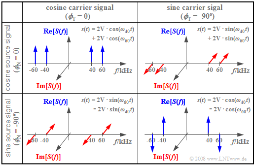
$\text{Example 3:}$ The following diagram shows the spectral functions $S(f)$ for different values of $ϕ_{\rm T}$ and $ϕ_{\rm N}$, respectively. The other parameters are assumed to be $f_{\rm T} = 50\text{ kHz}$, $f_{\rm N} = 10\text{ kHz}$ and $A_{\rm N} = 4\text{ V}$. Thus, the magnitudes of all Dirac delta lines are $A_{\rm N}/4 = 1\text{ V}$.
- The upper left diagram shows the case just discussed: Both the carrier and the source signal are cosine. Thus, the amplitude-modulated signal $s(t)$ is composed of two cosine oscillations with $ω_{60} = 2 π · 60\text{ kHz}$ and $ω_{40} = 2 π · 40\text{ kHz}$.
- For the other three constellations, at least one of the signals $q(t)$ or $z(t)$ is sinusoidal, so that $s(0) = 0$ always holds. Thus, for these spectra, the sum of the four pulse weights each add up to zero.
- The bottom right diagram depicts $s(t) = A_{\rm N} · \sin(ω_{\rm N} t) · \sin(ω_{\rm T}t)$. Multiplying two odd functions yields the even function $s(t)$ and thus a real spectrum $S(f)$. In contrast, the other two constellations each result in imaginary spectral functions.
Double-Sideband Amplitude Modulation with carrier
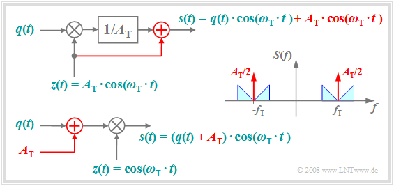
The following diagram shows how to get from "DSB-AM without carrier" to the better known variant "DSB-AM with carrier". This has the advantage that the demodulator can be realized much more easily and cheaply by a simple manipulation at the transmitter.
The diagram is to be interpreted as follows:
- The top plot shows the physical model of the "DSB-AM with carrier", with changes from the "DSB-AM without carrier" highlighted in red.
- The carrier signal $z(t) = A_{\rm T} · \cos(ω_{\rm T} · t)$ is added to the signal $s(t)$, which causes two additional Dirac delta functions in the spectrum $±f_{\rm T}$, each with impulse weight $A_{\rm T}/2$.
- Adding the DC signal $A_{\rm T}$ to the source signal and then multiplying by the dimensionless carrier $z(t)$ as shown in the lower sketch results in the same signal $s(t)$ and spectrum $S(f)$ as above.
- Thus, the second representation is equivalent to the upper model. In both cases the carrier phase is only set to $ϕ_{\rm T} = 0$ for the sake of simplified presentation.
$\text{Example 4:}$ The "double-sideband amplitude modulation with carrier" still finds its main application in radio transmissions for
- long wave $($frequency range $\text{30 kHz}$ ... $\text{300 kHz})$,
- medium wave $($frequency range $\text{300 kHz}$ ... $\text{3 MHz})$,
- short wave $($frequency range $\text{3 MHz}$ ... $\text{30 MHz})$.
However, these frequencies are increasingly being made available for digital applications, e.g. "Digital Video Broadcast" $\rm (DVB)$.
An application of "double-sideband amplitude modulation without carrier" exists for example in FM stereo broadcasting:
- Here, the differential signal between the two stereo channels is amplitude modulated (without carrier) at $\text{39 kHz}$.
- Then the sum signal of the two channels $($each in the range $\text{30 Hz}$ ... $\text{15 kHz})$ is combined with the differential signal and an auxiliary carrier at $\text{19 kHz}$. Then, this combined signal is frequency modulated.
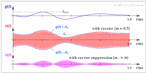
$\text{Example 5:}$ The following signal waveforms are intended to further clarify the principle of the modulation method "DSB-AM with carrier".
- In the upper diagram you see a section of the source signal $q(t)$ with frequencies in the range $\vert f \vert \le 4\text{ kHz}$.
- $s(t)$ is obtained by adding the DC component $A_{\rm T}$ to $q(t)$ and multiplying this summed signal by the carrier $z(t)$ of frequency $f_{\rm T} = 100\text{ kHz}$ ⇒ see middle diagram.
- In the lower diagram you see for comparison the transmitted signal of the "DSB-AM without carrier" ⇒ "DSB-AM with carrier suppression".
A comparison of these signal waveforms shows:
- By adding the DC component $A_{\rm T}$ the signal $q(t)$ can now be seen in the envelope of $s(t)$.
- Thus, $\text{envelope demodulation}$ can be applied, which is easier and cheaper to implement than coherent $\text{synchronous demodulation}$.
- However, a prerequisite for the application of the envelope demodulator is a modulation depth $m <1$.
- This parameter is defined as follows:
- $$m = \frac{q_{\rm max} }{A_{\rm T} } \hspace{0.3cm}{\rm with}\hspace{0.3cm} q_{\rm max} = \max_{t} \hspace{0.05cm} \vert q(t) \vert\hspace{0.05cm}.$$
$\text{Conclusions:}$
- The advantage of a simpler demodulator is traded off with a much higher transmit power, since the power of the carrier cannot be used for demodulation.
- Furthermore, care must be taken to ensure that the source signal does not contain a DC component, since this would be masked by the carrier.
- For speech and music signals, however, this is not a major restriction.
Describing DSB-AM with carrier using the analytical signal
In the further course of this chapter, for the sake of simplifying the graphs, the spectrum $S_+(f)$ of the $\text{analytical signal}$ is usually given instead of the actual, physical spectrum $S(f)$.
As an example, let us consider "DSB-AM with carrier" and the following signals:
- $$\begin{align*}s(t) & = \left(q(t) + A_{\rm T}\right) \cdot \cos(\omega_{\rm T}\cdot t + \phi_{\rm T})\hspace{0.05cm}, \\ \\ q(t) & = A_{\rm N} \cdot \cos(\omega_{\rm N}\cdot t + \phi_{\rm N})\hspace{0.05cm}.\end{align*}$$
Then the corresponding analytical signal is:
- $$s_+(t) = A_{\rm T} \cdot {\rm e}^{{\rm j}\hspace{0.03cm} \cdot \hspace{0.01cm}(\omega_{\rm T}\cdot \hspace{0.02cm}t \hspace{0.05cm}+ \hspace{0.05cm}\phi_{\rm T})}+ \frac{A_{\rm N}}{2} \cdot {\rm e}^{{\rm j}\hspace{0.03cm} \cdot \hspace{0.01cm}((\omega_{\rm T} \hspace{0.05cm}+ \hspace{0.05cm} \omega_{\rm N} )\hspace{0.02cm}\cdot \hspace{0.02cm}t \hspace{0.05cm}+ \hspace{0.05cm} \phi_{\rm T}+ \phi_{\rm N})} + \frac{A_{\rm N}}{2} \cdot {\rm e}^{{\rm j}\hspace{0.03cm} \cdot \hspace{0.01cm}((\omega_{\rm T} \hspace{0.05cm}- \hspace{0.05cm} \omega_{\rm N} )\hspace{0.02cm}\cdot \hspace{0.02cm}t \hspace{0.05cm}+ \hspace{0.05cm} \phi_{\rm T}- \phi_{\rm N})} \hspace{0.05cm}.$$
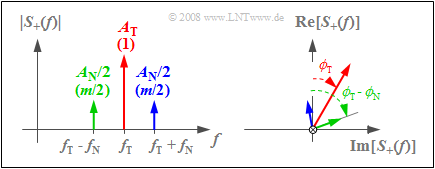
The corresponding spectral function $S_+(f)$ consists of three Dirac delta lines, each with complex weights corresponding to the graph:
- The left sketch shows $|S_+(f)|$. $A_{\rm T}$ indicates the weight of the carrier and $A_{\rm N}/2$ indicates the weights of $\rm USB$ (upper sideband) and $\rm LSB$ (lower sideband).
- The values normalized to $A_{\rm T}$ are given in parentheses. Since $q_{\rm max} = A_{\rm N}$ holds here, the modulation depth $m = A_{\rm N}/A_{\rm T}$ gives $m/2$ as the normalized weights of both the upper and lower sideband.
- The right sketch depicts the direction of the frequency axis and shows the phase angles of carrier $(ϕ_{\rm T})$, of $\rm LSB$ $(ϕ_{\rm T} - ϕ_{\rm N})$ and of $\rm USB$ $(ϕ_{\rm T} + ϕ_{\rm N})$.
Amplitude modulation with a quadratic characteristic curve
Nonlinearities are usually undesirable and troublesome in Communications Engineering. As explained in the chapter "Nonlinear Distortions" of the book "Linear and Time Invariant Systems”, they lead to the facts that:
- the superposition principle is no longer applicable,
- the transmission behavior depends on the magnitude of the input signal, and
- the distortions are of nonlinear nature and thus irreversible.
A nonlinearity of the general form
- $$y(t) = c_0 + c_1 \cdot x(t) + c_2 \cdot x^2(t)+ c_3 \cdot x^3(t) + \text{...}$$
can also be used to implement $\text{DSB}\hspace{0.05cm}–\hspace{-0.05cm}\text{AM}$. Provided that
- only the coefficients $c_1$ and $c_2$ are present, and
- the input signal $x(t) = q(t) + z(t)$ is applied,
we obtain the nonlinearity's output signal:
- $$y(t) = c_1 \cdot q(t) + c_1 \cdot z(t) + c_2 \cdot q^2(t)+ 2 \cdot c_2 \cdot q(t)\cdot z(t)+ c_2 \cdot z^2(t)\hspace{0.05cm}.$$
The first, third, and last components are – in terms of spectra – at $|\hspace{0.05cm} f \hspace{0.05cm}| ≤ 2 · B_{\rm NF}$ and $|\hspace{0.05cm} f\hspace{0.05cm} | = 2 · f_{\rm T}$, respectively.
Removing these signal components by a band-pass and considering $z(t) = A_{\rm T} · \cos(ω_{\rm T} · t)$, we obtain the equation typical for "DSB-AM with carrier"
(only the second and fourth terms remain):
- $$s(t) = c_1 \cdot A_{\rm T} \cdot \cos(\omega_{\rm T} \cdot t ) + 2 \cdot c_2 \cdot A_{\rm T} \cdot q(t)\cdot \cos(\omega_{\rm T} \cdot t )\hspace{0.05cm}.$$
The modulation depth in this realization form is variable by the coefficients $c_1$ and $c_2$ :
- $$m = \frac{2 \cdot c_2 \cdot q_{\rm max}}{c_1} \hspace{0.05cm}.$$
- A diode and a field-effect transistor both approximate such a quadratic characteristic curve and can thus be used to realize DSB-AM.
- However, cubic components $(c_3 ≠ 0)$ and higher order nonlinearities lead to (large) nonlinear distortions.
Exercises for the chapter
Exercise 2.1: DSB-AM with Cosine? Or with Sine?
Exercise 2.1Z: DSB-AM without/with Carrier
Exercise 2.2: Modulation Depth
Exercise 2.2Z: Power Consideration
Exercise 2.3: DSB–AM Realization
Exercise 2.3Z: DSB-AM due to Nonlinearity


