Difference between revisions of "Mobile Communications/Physical Layer for LTE"
| (58 intermediate revisions by 7 users not shown) | |||
| Line 2: | Line 2: | ||
{{Header | {{Header | ||
|Untermenü=LTE – Long Term Evolution | |Untermenü=LTE – Long Term Evolution | ||
| − | |Vorherige Seite= | + | |Vorherige Seite=The Application of OFDMA and SC-FDMA in LTE |
| − | |Nächste Seite= | + | |Nächste Seite=LTE-Advanced - a Further Development of LTE |
}} | }} | ||
| − | == | + | == General Description== |
<br> | <br> | ||
| − | + | The "Physical Layer" is the lowest layer in the OSI layer model of the "International Organization for Standardization" $\rm (ISO)$, which is also called "Bit Transmission Layer". It describes the physical transmission of bit sequences in LTE and the operation of the various channels according to the 3GPP specification. All specifications are valid for Frequency Division Duplex $\rm (FDD)$ as well as for Time Division Duplex $\rm (TDD)$. | |
| − | [[File: | + | [[File:EN_LTE_T_4_4_S1b_v1.png|right|frame|Protocol architecture for LTE|class=fit]] |
| + | The diagram shows the layers of the LTE protocol architecture. The communication between the individual layers takes place via three different types of channels: | ||
| + | *Logical channels,<br> | ||
| + | *Transport channels,<br> | ||
| + | *Physical channels. <br><br> | ||
| − | + | This chapter deals with the communication between transmitter and receiver in the lowest (red highlighted) "Physical Layer". Basically it should be noted: | |
| − | * | + | *Exactly like the Internet, LTE uses exclusively packet-based transmission, i.e. without specifically assigning resources to a single user.<br> |
| − | * | + | *The design of the LTE physical layer is therefore characterized by the principle of dynamically allocated network resources.<br> |
| − | * | + | *The physical layer plays a key role in the efficient allocation and utilization of available system resources. |
| − | |||
| − | |||
| − | * | + | According to this graphic the physical layer communicates with |
| + | *the block "Medium Access Control" $\rm (MAC)$ and exchanges information about the users and the regulation (control) of the network via the transport channels,<br> | ||
| − | * | + | *the block "Radio Resource Control" $\rm (RRC)$, where control commands and measurements are continuously exchanged to adapt the transmission to the channel quality.<br><br> |
| − | = | + | [[File:EN_LTE_T_4_4_S1.png|left|frame|Communication between the individual layers in the LTE downlink|class=fit]] |
<br> | <br> | ||
| − | + | The complexity of the LTE transmission is to be indicated by the left diagram, which has been directly adopted by the "European Telecommunications Standards Institute" $\rm (ETSI)$. It shows the communication between the individual layers (channels) and applies exclusively to the downlink.<br> | |
| − | |||
| − | * | + | *In the following sections we will take a closer look at the physical layer and the physical channels. We distinguish between uplink and downlink, but we will limit ourselves to the essentials. |
| − | + | *In reality, the individual channels take over a number of other functions, but their description would go beyond the scope of this tutorial. | |
| − | + | *If you are interested, you can find a detailed description in [HT09]<ref name= 'HT09'>Holma, H.; Toskala, A.: LTE for UMTS - OFDMA and SC-FDMA Based Radio Access. Wiley & Sons, 2009.</ref>. | |
| − | + | <br clear=all> | |
| − | + | == Physical channels in uplink== | |
| − | |||
| − | == | ||
<br> | <br> | ||
| − | LTE | + | LTE uses the multiple access method [[Mobile_Communications/The_Application_of_OFDMA_and_SC-FDMA_in_LTE#Functionality_of_SC-FDMA|$\rm SC–FDMA$]] in the uplink transmission from the terminal device to the base station. Accordingly, the following physical channels exist in the 3GPP specification: |
| − | * | + | *Physical Uplink Shared Channel $\rm (PUSCH)$,<br> |
| − | + | *Physical Random Access Channel $\rm (PRACH)$,<br> | |
| − | * | + | *Physical Uplink Control Channel $\rm (PUCCH)$.<br> |
| − | |||
| − | + | The user data are transmitted in the physical channel $\rm (PUSCH)$. The transmission speed depends on how much bandwidth is available to the user at that moment. The transmission is based on dynamically allocated resources in time and frequency range with a resolution of one millisecond or 180 kHz. This allocation is performed by the [[Mobile_Communications/Physical_Layer_for_LTE#Scheduling_for_LTE| $\text{Scheduler}$]] in the base station ("eNodeB"). A terminal device cannot transmit any data without instructions from the base station.<br> | |
| − | + | The exception is the use of the physical channel $\rm PRACH$, the only channel in the LTE uplink with non–synchronized transmission. The function of this channel is the request for permission to send data via one of the other two physical channels. By sending a "Cyclic Prefix" and a signature on the PRACH, the terminal and base station are synchronized and are thus ready for further transmissions.<br> | |
| − | + | The third uplink channel $\rm PUCCH$ is used exclusively for the transmission of control signals. By this one understands | |
| − | *positive | + | *positive and negative acknowledgements of reception $\rm (ACK/NACK)$,<br> |
| + | *requests for repeated transmission $($in case of $\rm NACK)$, and<br> | ||
| + | *the exchange of channel quality information between the terminal and the base station.<br><br> | ||
| − | + | If, in addition to the control data, user data are sent from the terminal to the base station at the same time, such control signals can also be transmitted via the PUSCH. If no user data is to be transmitted, PUCCH is used instead.<br> | |
| − | * | + | A simultaneous use of PUSCH and PUCCH is not possible due to restrictions of the transmission method "SC–FDMA". If only one "Shared Channel" had been selected for all control information, one would have had to choose between |
| + | *intermittent problems with user data transmission, or<br> | ||
| + | *permanently too few resources for the control information.<br><br> | ||
| − | + | The information about the channel quality is obtained by means of so-called "reference symbols". As indicators for the channel quality this information is then sent to | |
| + | * "Channel Quality Indicator" $\rm (CQI)$, and<br> | ||
| − | + | * "Rank Indicator" $\rm (RI)$.<br><br> | |
| − | <br> | ||
| − | |||
| − | + | A detailed explanation of the quality guarantee can be found, for example, in [HR09]<ref name='HR09'>Homayounfar, K.; Rohani, B.: CQI Measurement and Reporting in LTE: A New Framework. | |
| − | + | IEICE Technical Report, Vol. 108, No. 445, 2009.</ref> and [HT09]<ref name='HT09'></ref>.<br> | |
| − | |||
| − | |||
| − | |||
| − | + | {{GraueBox|TEXT= | |
| + | $\text{Example 1:}$ The reference symbols or channel quality information are distributed in the PUSCH according to the following graphic. | ||
| − | + | [[File:EN_LTE_T_4_4_S2.png|right|frame|Distribution of reference symbols and user data in PUSCH|class=fit]] | |
| − | |||
| − | + | The graphic describes the arrangement of the useful information and the signaling data in a "virtual subcarrier". | |
| + | *"Virtual" because SC–FDMA does not have subcarriers like OFDMA. | ||
| − | + | *The reference symbols are necessary to estimate the channel quality.<br> | |
| − | * | ||
| − | * | + | *This information is also transferred as "Channel Quality Indicator" $\rm (CQI)$ or as "Rank Indicator" $\rm (RI)$ via the PUSCH.}}<br><br> |
| − | + | == Physical channels in downlink== | |
| − | |||
| − | == | ||
<br> | <br> | ||
| − | + | In contrast to the uplink, LTE uses the multiple access method [[Mobile_Communications/The_Application_of_OFDMA_and_SC-FDMA_in_LTE#Differences_between_OFDMA_and_SC-FDMA|$\rm OFDMA$]] in the downlink, i.e. during transmission from the base station to the terminal. Accordingly, the 3GPP consortium specified the following physical channels for this purpose: | |
| − | * | + | *Physical Downlink Shared Channel</i> $\rm (PDSCH)$,<br> |
| − | * | + | * Physical Downlink Control Channel</i> $\rm (PDCCH)$,<br> |
| − | * | + | * Physical Control Format Indicator Channel</i> $\rm (PCFICH)$,<br> |
| − | * | + | * Physical Hybrid ARQ Indicator Channel</i> $\rm (PHICH)$,<br> |
| − | * | + | * Physical Broadcast Channel</i> $\rm (PBCH)$,<br> |
| − | * | + | * Physical Multicast Channel</i> $\rm (PMCH)$.<br><br> |
| − | + | The user data are transmitted via the $\rm PDSCH$. The resource allocation is done both in the time domain (with a resolution of one millisecond) and in the frequency domain (resolution: 180 kHz). Due to the use of OFDMA as transmission method, the individual speed of each user depends on the number of assigned resource blocks (à 180 kHz). A "eNodeB" allocates the resources related to the channel quality of each individual user.<br> | |
| − | + | The $\rm PDCCH$ contains all information regarding the allocation of resource blocks or bandwidth for both the uplink and the downlink. A terminal device thereby receives information about how many resources are available.<br> | |
| − | + | [[File:EN_LTE_T_4_4_S3.png|right|frame|Division between PDCCH and PDSCH <br>in the LTE downlink]] | |
| − | [[File: | + | The diagram on the right shows an example of the division between the channels PDCCH and PDSCH: |
| + | *The PDCCH can occupy up to four symbols per subframe (in the graphic: two).<br> | ||
| + | *This leaves twelve time slots for the user data (i.e. for the channel PDSCH). | ||
| − | |||
| − | |||
| − | * | + | Via channel $\rm PCFICH$ the terminal device is informed how many symbols are to be assigned to the control information of the PDCCH. The purpose of this dynamic division between control and user data is as follows: |
| + | *For example, many users can be supported in this way, each with a low data rate. This scenario requires more tuning, which means that in this case the PDCCH would have to contain three or four symbols.<br> | ||
| − | + | *On the other hand, the overhead caused by PDCCH can be reduced by assigning a high data rate to only a few concurrent users. | |
| − | |||
| − | |||
| − | |||
| − | |||
| − | |||
| − | + | [[File:EN_LTE_T_4_4_S3b.png|left|frame|Distribution of reference symbols in the LTE downlink|class=fit]] | |
| + | <br><br><br><br><br><br><br><br> | ||
| + | In addition to the $\rm PDCCH$, reference symbols are also required in the downlink to estimate the channel quality and calculate the "Channel Quality Indicator" (CQI). These reference symbols are distributed over the subcarriers (different frequencies) or symbols (different times) as shown in the left graphic. | ||
| + | <br clear=all> | ||
| + | Regarding the other physical channels of the LTE downlink is to be noted: | ||
| + | *The only purpose of the downlink channel $\rm PHICH$ ("Physical Hybrid ARQ Indicator Channel") is to signal whether a packet sent in the uplink has arrived.<br> | ||
| − | + | *On the broadcast channel $\rm PBCH$ ("Physical Broadcast Channel") the base stations send system information with operating parameters as well as synchronization signals, which are required for registration in the network, to all mobile terminals in the radio cell approximately every 40 milliseconds.<br> | |
| − | + | *The multicast channel $\rm PMCH$ ("Physical Multicast Channel") has a similar purpose, information for so-called multicast transmissions is sent to several receivers simultaneously through this channel. This could be, for example, mobile television via LTE, which is planned for a future release, or something similar.<br> | |
| − | |||
| − | + | == Processes on the physical layer== | |
| + | <br> | ||
| + | By "Processes in the physical layer" one understands different methods and procedures, which are used in the bit transmission layer. Among them fall among other things: | ||
| + | :*Timing Advance,<br> | ||
| + | :*Paging,<br> | ||
| + | :*Random Access,<br> | ||
| + | :*Channel Feedback Reporting,<br> | ||
| + | :*Power Control,<br> | ||
| + | :*Hybrid Adaptive Repeat and Request.<br><br> | ||
| − | + | A complete list with the corresponding description can be found in [HT09]<ref name='HT09'></ref>. Only the last two procedures will be discussed in more detail here.<br><br> | |
| − | == | + | == Power control with LTE== |
<br> | <br> | ||
| − | + | By "Power Control" one understands generally the control of the transmission power with the goal, | |
| − | *< | + | *to improve the transmission quality,<br> |
| + | *to increase the network capacity, and<br> | ||
| + | *to reduce the power consumption.<br><br> | ||
| − | *< | + | With regard to the last point, the standardization of LTE had to take this into account: |
| + | *On the one hand, the power consumption in the end devices was to be minimized in order to guarantee longer battery runtimes for them.<br> | ||
| + | *On the other hand, it should be avoided that the base stations have to provide too much power.<br><br> | ||
| − | + | With LTE, power control is only applied in the uplink, whereas it is more of an "slow" power control. This means that the procedure specified in LTE does not have to react as quickly as for example in UMTS ("W–CDMA" ). The reason is that by using the orthogonal carrier system "SC–FMDA" the so-called [[Examples_of_Communication_Systems/Nachrichtentechnische_Aspekte_von_UMTS#Near.E2.80.93Far.E2.80.93Effekt| $\text{Near–Far problem}$]] does not exist. | |
| − | * | + | *To be precise, for LTE the power control does not control the absolute power, but the power-spectral density, i.e. the power per bandwidth.<br> |
| − | *< | + | *Instead of trying to smooth power peaks by temporarily reducing the transmission power, power peaks can also be used to increase the data rate for a short time.<br><br> |
| − | + | All in all, LTE power control is intended to find the optimum balance between the lowest possible power and at the same time interference that is still acceptable for the transmission quality (QoS). This is specifically achieved by estimating the loss during transmission and by calculating a correction factor according to the current site characteristics. The statements made here are largely taken from [DFJ08]<ref name ='DFJ08'>Dahlman, E., Furuskär A., Jading Y., Lindström M., Parkvall, S.: Key Features of the LTE Radio Interface. Ericsson Review No. 2, 2008.</ref>. | |
| − | |||
| − | < | + | == Hybrid Adaptive Repeat and Request == |
| − | + | <br> | |
| − | + | Every communication system needs a scheme for retransmission of lost data due to transmission errors to ensure sufficient transmission quality. In LTE "Hybrid Adaptive Repeat and Request" $\rm (HARQ)$ was specified for this purpose. This procedure is also used in [[Examples_of_Communication_Systems/Further_Developments_of_UMTS#HARQ_procedure_and_.22Node_B_Scheduling.22| $\text{UMTS}$]] in a similar form.<br> | |
| − | |||
| − | |||
| − | |||
| − | |||
| − | |||
| − | + | The procedure based on the "stop–and–wait" technique is as follows: | |
| − | * | + | *After a terminal device has received a packet from the base station, it is decoded and feedback is sent via the [[Mobile_Communications/Physical_Layer_for_LTE#Physical channels in uplink| $\rm PUCCH$]].<br> |
| + | *In case of a failed transmission ("NACK") the packet is resent. Only if the transmission was successful (Feedback: "ACK"), the next packet is sent.<br><br> | ||
| − | + | In order to ensure continuous data transfer despite the "stop–and–wait" procedure, LTE requires several simultaneous HARQ processes. In LTE, eight parallel processes are used both in the uplink and in the downlink.<br> | |
| − | + | {{GraueBox|TEXT= | |
| + | $\text{Example 2:}$ The graphic illustrates how it works with eight simultaneous HARQ processes: | ||
| − | * | + | [[File:EN_LTE_T_4_4_S4a.png|right|frame|HARQ in LTE with eight simultaneous processes|class=fit]] |
| + | *In this example, the first process fails in the first attempt to transfer packet '''1'''. | ||
| + | *The receiver tells this "Fail" to the transmitter by a "NACK". In contrast, the second parallel process is successful with its first packet: "Pass".<br> | ||
| + | *In the next step (i.e. after the other seven HARQ processes have sent) the first HARQ retransmits its last sent packet due to the acknowledgement "NACK". <br> | ||
| − | * | + | *The second process sends a new packet due to the acknowledgement "ACK" now.<br><br> |
| − | + | The other processes, which were ignored in this example, proceed in the same way.}}<br> | |
| − | == | + | == Modulation for LTE == |
<br> | <br> | ||
| − | + | LTE uses the modulation method [[Modulation_Methods/Quadrature_Amplitude_Modulation#General_description_and_signal_space_allocation|$\text{Quadrature Amplitude Modulation}$]] $\rm (QAM)$. Different variants are available in the uplink as well as in the downlink, namely | |
| − | + | [[File:P ID2290 LTE T 4 4 S5a v2.png|right|frame|Possible QAM signal space constellations in LTE|class=fit]] | |
| − | + | *4–QAM (identical to QPSK) ⇒ two bits per symbol,<br> | |
| − | + | *16–QAM ⇒ four bits per symbol,<br> | |
| + | *64–QAM ⇒ six bits per symbol.<br> | ||
| − | |||
| − | |||
| − | + | <i>Note:</i> QAM is not an LTE specific development, but is also used in many already established wired transmission methods, such as those of [[Examples_of_Communication_Systems/Allgemeine_Beschreibung_von_DSL|$\rm DSL$]] ("Digital Subscriber Line"). | |
| − | [[File:P | + | [[File:P ID2291 LTE T 4 4 S5b v1.png|left|frame|Modulation method depends on distance from base station]] |
| + | <br><br><br><br><br><br> | ||
| + | The signal space constellations of these variants are shown in the left graphic. Depending on the environment and distance to the base station, the [[Mobile_Communications/Physical_Layer_for_LTE#Scheduling_for_LTE|$\text{Scheduler}$]] selects the appropriate QAM method: | ||
| − | * | + | *64–QAM allows the best data rates, but is also the most susceptible to interference and is therefore only used near the base stations. The weaker the connection, the simpler the modulation method must be, which also reduces the spectral efficiency (in bit/s per Hertz).<br> |
| + | *Very robust is 4–QAM with only two bits per symbol (one each for real and imaginary part). This can be used for much larger distances than for example 16–QAM. | ||
| + | *Due to the exact same signal space constellation the 4–QAM is often called "Quaternary Phase Shift Keying" $\rm (QPSK)$. The four signal space points are arranged in a square pattern (QAM principle). But they also lie on a circle (characteristic of "PSK"). | ||
| + | <br clear=all> | ||
| + | [[File:EN_LTE_T_4_4_S5c_neu.png|right|frame|Throughput depending on SNR|class=fit]] | ||
| − | + | The graphic on the right from [MG08]<ref name='MG08'>Myung, H.; Goodman, D.: Single Carrier FDMA - A New Air Interface for Long Term Evolution. West Sussex: John Wiley & Sons, 2008.</ref> gives the following facts: | |
| + | *With 4–QAM or QPSK (two bit/symbol) a throughput of almost one Mbit/s is achieved in the LTE uplink with the assumptions made in [MG08]. | ||
| − | + | *Only above a certain "Signal–to–Noise Ratio" $\rm (SNR)$ a higher level QAM is used, for example 16–QAM (4 bit/symbol) or 64–QAM (8 bit/symbol).<br> | |
| − | + | *If the SNR is sufficiently large, increasing the number of stages will lead to better results regarding the data throughput. | |
| − | |||
| − | |||
| − | |||
| − | |||
| − | + | It should be noted that the low-rate QPSK (4–QAM) is always used in the control channels, since, | |
| + | #on the one hand, this information do not require high data rates due to their small size, and, | ||
| + | #on the other hand, should be received (almost) error-free due to their importance.<br> | ||
| − | |||
| − | [[ | + | An exception is the channel [[Mobile_Communications/Physical Layer for LTE#Physical channels in uplink| $\rm PUSCH$]] in the uplink, which transmits both user and control data. For this reason, the same modulation type is used here for both signals. |
| + | <br clear=all> | ||
| − | + | == Scheduling for LTE == | |
| − | [[File: | + | <br> |
| − | * | + | [[File:LTE_T_4_4_S6_v2.png|right|frame|Functionality of the scheduler in the LTE uplink|class=fit]] |
| − | + | All LTE base stations contain a scheduler that can be switched between | |
| − | * | + | *a total transfer rate as high as possible<br> |
| − | + | *with sufficiently good Quality of Service $\rm (QoS)$.<br><br> | |
| − | |||
| − | + | A possible QoS criterion is for example the "packet delay duration". So the scheduler tries to optimize the overall situation by using algorithms.<br> | |
| − | + | Scheduling is necessary to ensure a fair distribution of resources. A concrete example is that a user who currently has a poor channel and therefore low efficiency must still be allocated sufficient resources, otherwise the desired (and guaranteed) transmission quality cannot be maintained.<br> | |
| − | + | The scheduler controls the selection of the modulation method and the subcarrier–mapping. The functionality of the scheduler is illustrated by the graphic for the uplink. Similar statements apply to the downlink.<br> | |
| − | |||
| − | |||
| − | |||
| − | |||
| − | * | + | {{BlueBox|TEXT= |
| + | $\text{Conclusion:}$ Based on [SABM06]<ref name ='SABM06'>Schmidt, M.; Ahn, N.; Braun, V.; Mayer, H.P.: Performance of QoS and Channel-aware Packet Scheduling for LTE Downlink. Alcatel-Lucent, 2006. </ref>, [WGM07]<ref name ='WGM07'>Wang, X.; Giannakis, G.B.; Marques, A.G.: A Unified Approach to QoS - Guaranteed Scheduling or Channel-Adaptive Wireless Networks. <br>Proceedings of the IEEE, Vol. 95, No. 12, Dec. 2007.</ref> and [MG08]<ref name ='MG08'></ref> should be noted in summary: | ||
| + | *Scheduler algorithms are often very complicated due to the many optimization criteria, parameters and possible scenarios. Therefore, the design is usually based on an optimal system in which each base station knows the channel transmission functions sufficiently well at all times and transmission delays are unproblematic.<br> | ||
| − | + | *From these boundary conditions, different approaches are created with the help of mathematical analyzes [WGM07]<ref name ='WGM07'></ref>, whose effectiveness can only be verified by practical tests. A detailed description of such tests can be found in [MG08]<ref name ='MG08'></ref>.<br> | |
| − | + | *In principle, the overall transmission rate can be increased by channel-dependent scheduling (exploiting frequency selectivity), but this involves a large overhead, since test signals must be sent over the entire bandwidth. The information has to be distributed to all end devices if the full optimization potential is to be exploited.<br> | |
| − | |||
| − | * | + | *In various tests, the clear and significant advantages (doubling of throughput) of channel based scheduling were shown, but also the expected losses with faster moving users. More about this in the recommended document [SABM06]<ref name ='SABM06'></ref>.}}<br> |
| − | + | Due to many advantages, scheduling is an integral part of the LTE Release 8, specified by 3GPP.<br> | |
| − | == | + | ==Exercises for the chapter== |
<br> | <br> | ||
| − | + | [[Aufgaben:Exercise 4.4: Modulation in LTE]] | |
| − | |||
| − | + | [[Aufgaben:Exercise 4.4Z: Physical Channels in LTE]] | |
| − | |||
| − | |||
| − | |||
| − | |||
| − | |||
| − | |||
| − | |||
| − | |||
| − | |||
| − | |||
| − | |||
| − | |||
| − | |||
| − | |||
| − | |||
| − | |||
| − | |||
| − | |||
| − | |||
| − | |||
| − | |||
| − | |||
| − | |||
| − | == | + | ==References== |
<references/> | <references/> | ||
Latest revision as of 14:52, 20 February 2023
Contents
General Description
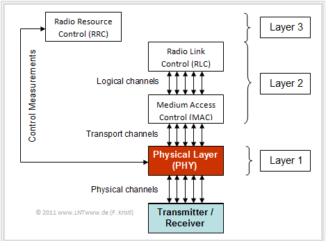
The "Physical Layer" is the lowest layer in the OSI layer model of the "International Organization for Standardization" $\rm (ISO)$, which is also called "Bit Transmission Layer". It describes the physical transmission of bit sequences in LTE and the operation of the various channels according to the 3GPP specification. All specifications are valid for Frequency Division Duplex $\rm (FDD)$ as well as for Time Division Duplex $\rm (TDD)$.
The diagram shows the layers of the LTE protocol architecture. The communication between the individual layers takes place via three different types of channels:
- Logical channels,
- Transport channels,
- Physical channels.
This chapter deals with the communication between transmitter and receiver in the lowest (red highlighted) "Physical Layer". Basically it should be noted:
- Exactly like the Internet, LTE uses exclusively packet-based transmission, i.e. without specifically assigning resources to a single user.
- The design of the LTE physical layer is therefore characterized by the principle of dynamically allocated network resources.
- The physical layer plays a key role in the efficient allocation and utilization of available system resources.
According to this graphic the physical layer communicates with
- the block "Medium Access Control" $\rm (MAC)$ and exchanges information about the users and the regulation (control) of the network via the transport channels,
- the block "Radio Resource Control" $\rm (RRC)$, where control commands and measurements are continuously exchanged to adapt the transmission to the channel quality.
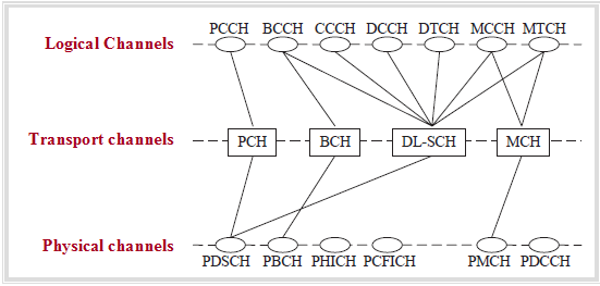
The complexity of the LTE transmission is to be indicated by the left diagram, which has been directly adopted by the "European Telecommunications Standards Institute" $\rm (ETSI)$. It shows the communication between the individual layers (channels) and applies exclusively to the downlink.
- In the following sections we will take a closer look at the physical layer and the physical channels. We distinguish between uplink and downlink, but we will limit ourselves to the essentials.
- In reality, the individual channels take over a number of other functions, but their description would go beyond the scope of this tutorial.
- If you are interested, you can find a detailed description in [HT09][1].
Physical channels in uplink
LTE uses the multiple access method $\rm SC–FDMA$ in the uplink transmission from the terminal device to the base station. Accordingly, the following physical channels exist in the 3GPP specification:
- Physical Uplink Shared Channel $\rm (PUSCH)$,
- Physical Random Access Channel $\rm (PRACH)$,
- Physical Uplink Control Channel $\rm (PUCCH)$.
The user data are transmitted in the physical channel $\rm (PUSCH)$. The transmission speed depends on how much bandwidth is available to the user at that moment. The transmission is based on dynamically allocated resources in time and frequency range with a resolution of one millisecond or 180 kHz. This allocation is performed by the $\text{Scheduler}$ in the base station ("eNodeB"). A terminal device cannot transmit any data without instructions from the base station.
The exception is the use of the physical channel $\rm PRACH$, the only channel in the LTE uplink with non–synchronized transmission. The function of this channel is the request for permission to send data via one of the other two physical channels. By sending a "Cyclic Prefix" and a signature on the PRACH, the terminal and base station are synchronized and are thus ready for further transmissions.
The third uplink channel $\rm PUCCH$ is used exclusively for the transmission of control signals. By this one understands
- positive and negative acknowledgements of reception $\rm (ACK/NACK)$,
- requests for repeated transmission $($in case of $\rm NACK)$, and
- the exchange of channel quality information between the terminal and the base station.
If, in addition to the control data, user data are sent from the terminal to the base station at the same time, such control signals can also be transmitted via the PUSCH. If no user data is to be transmitted, PUCCH is used instead.
A simultaneous use of PUSCH and PUCCH is not possible due to restrictions of the transmission method "SC–FDMA". If only one "Shared Channel" had been selected for all control information, one would have had to choose between
- intermittent problems with user data transmission, or
- permanently too few resources for the control information.
The information about the channel quality is obtained by means of so-called "reference symbols". As indicators for the channel quality this information is then sent to
- "Channel Quality Indicator" $\rm (CQI)$, and
- "Rank Indicator" $\rm (RI)$.
A detailed explanation of the quality guarantee can be found, for example, in [HR09][2] and [HT09][1].
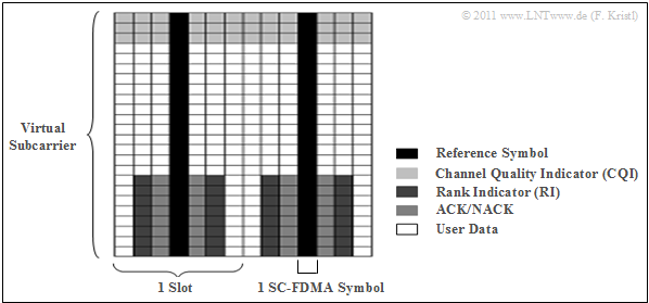
$\text{Example 1:}$ The reference symbols or channel quality information are distributed in the PUSCH according to the following graphic.
The graphic describes the arrangement of the useful information and the signaling data in a "virtual subcarrier".
- "Virtual" because SC–FDMA does not have subcarriers like OFDMA.
- The reference symbols are necessary to estimate the channel quality.
- This information is also transferred as "Channel Quality Indicator" $\rm (CQI)$ or as "Rank Indicator" $\rm (RI)$ via the PUSCH.
Physical channels in downlink
In contrast to the uplink, LTE uses the multiple access method $\rm OFDMA$ in the downlink, i.e. during transmission from the base station to the terminal. Accordingly, the 3GPP consortium specified the following physical channels for this purpose:
- Physical Downlink Shared Channel $\rm (PDSCH)$,
- Physical Downlink Control Channel $\rm (PDCCH)$,
- Physical Control Format Indicator Channel $\rm (PCFICH)$,
- Physical Hybrid ARQ Indicator Channel $\rm (PHICH)$,
- Physical Broadcast Channel $\rm (PBCH)$,
- Physical Multicast Channel $\rm (PMCH)$.
The user data are transmitted via the $\rm PDSCH$. The resource allocation is done both in the time domain (with a resolution of one millisecond) and in the frequency domain (resolution: 180 kHz). Due to the use of OFDMA as transmission method, the individual speed of each user depends on the number of assigned resource blocks (à 180 kHz). A "eNodeB" allocates the resources related to the channel quality of each individual user.
The $\rm PDCCH$ contains all information regarding the allocation of resource blocks or bandwidth for both the uplink and the downlink. A terminal device thereby receives information about how many resources are available.
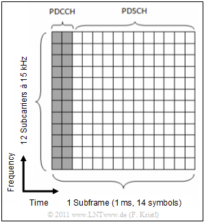
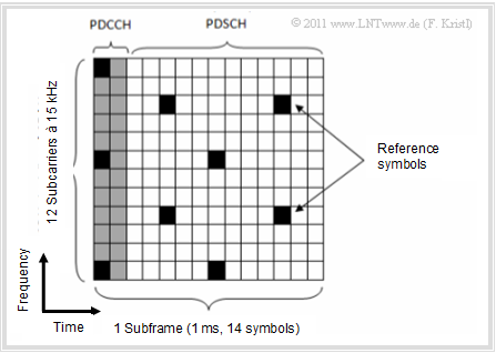
The diagram on the right shows an example of the division between the channels PDCCH and PDSCH:
- The PDCCH can occupy up to four symbols per subframe (in the graphic: two).
- This leaves twelve time slots for the user data (i.e. for the channel PDSCH).
Via channel $\rm PCFICH$ the terminal device is informed how many symbols are to be assigned to the control information of the PDCCH. The purpose of this dynamic division between control and user data is as follows:
- For example, many users can be supported in this way, each with a low data rate. This scenario requires more tuning, which means that in this case the PDCCH would have to contain three or four symbols.
- On the other hand, the overhead caused by PDCCH can be reduced by assigning a high data rate to only a few concurrent users.
In addition to the $\rm PDCCH$, reference symbols are also required in the downlink to estimate the channel quality and calculate the "Channel Quality Indicator" (CQI). These reference symbols are distributed over the subcarriers (different frequencies) or symbols (different times) as shown in the left graphic.
Regarding the other physical channels of the LTE downlink is to be noted:
- The only purpose of the downlink channel $\rm PHICH$ ("Physical Hybrid ARQ Indicator Channel") is to signal whether a packet sent in the uplink has arrived.
- On the broadcast channel $\rm PBCH$ ("Physical Broadcast Channel") the base stations send system information with operating parameters as well as synchronization signals, which are required for registration in the network, to all mobile terminals in the radio cell approximately every 40 milliseconds.
- The multicast channel $\rm PMCH$ ("Physical Multicast Channel") has a similar purpose, information for so-called multicast transmissions is sent to several receivers simultaneously through this channel. This could be, for example, mobile television via LTE, which is planned for a future release, or something similar.
Processes on the physical layer
By "Processes in the physical layer" one understands different methods and procedures, which are used in the bit transmission layer. Among them fall among other things:
- Timing Advance,
- Paging,
- Random Access,
- Channel Feedback Reporting,
- Power Control,
- Hybrid Adaptive Repeat and Request.
- Timing Advance,
A complete list with the corresponding description can be found in [HT09][1]. Only the last two procedures will be discussed in more detail here.
Power control with LTE
By "Power Control" one understands generally the control of the transmission power with the goal,
- to improve the transmission quality,
- to increase the network capacity, and
- to reduce the power consumption.
With regard to the last point, the standardization of LTE had to take this into account:
- On the one hand, the power consumption in the end devices was to be minimized in order to guarantee longer battery runtimes for them.
- On the other hand, it should be avoided that the base stations have to provide too much power.
With LTE, power control is only applied in the uplink, whereas it is more of an "slow" power control. This means that the procedure specified in LTE does not have to react as quickly as for example in UMTS ("W–CDMA" ). The reason is that by using the orthogonal carrier system "SC–FMDA" the so-called $\text{Near–Far problem}$ does not exist.
- To be precise, for LTE the power control does not control the absolute power, but the power-spectral density, i.e. the power per bandwidth.
- Instead of trying to smooth power peaks by temporarily reducing the transmission power, power peaks can also be used to increase the data rate for a short time.
All in all, LTE power control is intended to find the optimum balance between the lowest possible power and at the same time interference that is still acceptable for the transmission quality (QoS). This is specifically achieved by estimating the loss during transmission and by calculating a correction factor according to the current site characteristics. The statements made here are largely taken from [DFJ08][3].
Hybrid Adaptive Repeat and Request
Every communication system needs a scheme for retransmission of lost data due to transmission errors to ensure sufficient transmission quality. In LTE "Hybrid Adaptive Repeat and Request" $\rm (HARQ)$ was specified for this purpose. This procedure is also used in $\text{UMTS}$ in a similar form.
The procedure based on the "stop–and–wait" technique is as follows:
- After a terminal device has received a packet from the base station, it is decoded and feedback is sent via the $\rm PUCCH$.
- In case of a failed transmission ("NACK") the packet is resent. Only if the transmission was successful (Feedback: "ACK"), the next packet is sent.
In order to ensure continuous data transfer despite the "stop–and–wait" procedure, LTE requires several simultaneous HARQ processes. In LTE, eight parallel processes are used both in the uplink and in the downlink.
$\text{Example 2:}$ The graphic illustrates how it works with eight simultaneous HARQ processes:
- In this example, the first process fails in the first attempt to transfer packet 1.
- The receiver tells this "Fail" to the transmitter by a "NACK". In contrast, the second parallel process is successful with its first packet: "Pass".
- In the next step (i.e. after the other seven HARQ processes have sent) the first HARQ retransmits its last sent packet due to the acknowledgement "NACK".
- The second process sends a new packet due to the acknowledgement "ACK" now.
The other processes, which were ignored in this example, proceed in the same way.
Modulation for LTE
LTE uses the modulation method $\text{Quadrature Amplitude Modulation}$ $\rm (QAM)$. Different variants are available in the uplink as well as in the downlink, namely
- 4–QAM (identical to QPSK) ⇒ two bits per symbol,
- 16–QAM ⇒ four bits per symbol,
- 64–QAM ⇒ six bits per symbol.
Note: QAM is not an LTE specific development, but is also used in many already established wired transmission methods, such as those of $\rm DSL$ ("Digital Subscriber Line").
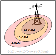
The signal space constellations of these variants are shown in the left graphic. Depending on the environment and distance to the base station, the $\text{Scheduler}$ selects the appropriate QAM method:
- 64–QAM allows the best data rates, but is also the most susceptible to interference and is therefore only used near the base stations. The weaker the connection, the simpler the modulation method must be, which also reduces the spectral efficiency (in bit/s per Hertz).
- Very robust is 4–QAM with only two bits per symbol (one each for real and imaginary part). This can be used for much larger distances than for example 16–QAM.
- Due to the exact same signal space constellation the 4–QAM is often called "Quaternary Phase Shift Keying" $\rm (QPSK)$. The four signal space points are arranged in a square pattern (QAM principle). But they also lie on a circle (characteristic of "PSK").
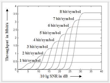
The graphic on the right from [MG08][4] gives the following facts:
- With 4–QAM or QPSK (two bit/symbol) a throughput of almost one Mbit/s is achieved in the LTE uplink with the assumptions made in [MG08].
- Only above a certain "Signal–to–Noise Ratio" $\rm (SNR)$ a higher level QAM is used, for example 16–QAM (4 bit/symbol) or 64–QAM (8 bit/symbol).
- If the SNR is sufficiently large, increasing the number of stages will lead to better results regarding the data throughput.
It should be noted that the low-rate QPSK (4–QAM) is always used in the control channels, since,
- on the one hand, this information do not require high data rates due to their small size, and,
- on the other hand, should be received (almost) error-free due to their importance.
An exception is the channel $\rm PUSCH$ in the uplink, which transmits both user and control data. For this reason, the same modulation type is used here for both signals.
Scheduling for LTE
All LTE base stations contain a scheduler that can be switched between
- a total transfer rate as high as possible
- with sufficiently good Quality of Service $\rm (QoS)$.
A possible QoS criterion is for example the "packet delay duration". So the scheduler tries to optimize the overall situation by using algorithms.
Scheduling is necessary to ensure a fair distribution of resources. A concrete example is that a user who currently has a poor channel and therefore low efficiency must still be allocated sufficient resources, otherwise the desired (and guaranteed) transmission quality cannot be maintained.
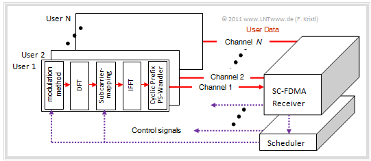
The scheduler controls the selection of the modulation method and the subcarrier–mapping. The functionality of the scheduler is illustrated by the graphic for the uplink. Similar statements apply to the downlink.
$\text{Conclusion:}$ Based on [SABM06][5], [WGM07][6] and [MG08][4] should be noted in summary:
- Scheduler algorithms are often very complicated due to the many optimization criteria, parameters and possible scenarios. Therefore, the design is usually based on an optimal system in which each base station knows the channel transmission functions sufficiently well at all times and transmission delays are unproblematic.
- From these boundary conditions, different approaches are created with the help of mathematical analyzes [WGM07][6], whose effectiveness can only be verified by practical tests. A detailed description of such tests can be found in [MG08][4].
- In principle, the overall transmission rate can be increased by channel-dependent scheduling (exploiting frequency selectivity), but this involves a large overhead, since test signals must be sent over the entire bandwidth. The information has to be distributed to all end devices if the full optimization potential is to be exploited.
- In various tests, the clear and significant advantages (doubling of throughput) of channel based scheduling were shown, but also the expected losses with faster moving users. More about this in the recommended document [SABM06][5].
Due to many advantages, scheduling is an integral part of the LTE Release 8, specified by 3GPP.
Exercises for the chapter
Exercise 4.4: Modulation in LTE
Exercise 4.4Z: Physical Channels in LTE
References
- ↑ 1.0 1.1 1.2 Holma, H.; Toskala, A.: LTE for UMTS - OFDMA and SC-FDMA Based Radio Access. Wiley & Sons, 2009.
- ↑ Homayounfar, K.; Rohani, B.: CQI Measurement and Reporting in LTE: A New Framework. IEICE Technical Report, Vol. 108, No. 445, 2009.
- ↑ Dahlman, E., Furuskär A., Jading Y., Lindström M., Parkvall, S.: Key Features of the LTE Radio Interface. Ericsson Review No. 2, 2008.
- ↑ 4.0 4.1 4.2 Myung, H.; Goodman, D.: Single Carrier FDMA - A New Air Interface for Long Term Evolution. West Sussex: John Wiley & Sons, 2008.
- ↑ 5.0 5.1 Schmidt, M.; Ahn, N.; Braun, V.; Mayer, H.P.: Performance of QoS and Channel-aware Packet Scheduling for LTE Downlink. Alcatel-Lucent, 2006.
- ↑ 6.0 6.1 Wang, X.; Giannakis, G.B.; Marques, A.G.: A Unified Approach to QoS - Guaranteed Scheduling or Channel-Adaptive Wireless Networks.
Proceedings of the IEEE, Vol. 95, No. 12, Dec. 2007.
