Difference between revisions of "Aufgaben:Exercise 4.5: Pseudo Noise Modulation"
From LNTwww
| Line 3: | Line 3: | ||
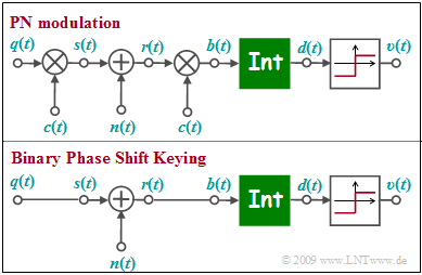
[[File:EN_Bei_A_4_5.png|right|frame|Equivalent circuit of PN modulation and BPSK]] | [[File:EN_Bei_A_4_5.png|right|frame|Equivalent circuit of PN modulation and BPSK]] | ||
| − | The graph above shows the equivalent circuit of "pseudo-noise" modulation ( | + | The graph above shows the equivalent circuit of "pseudo-noise" modulation ( ''Direct Sequence Spread Spectrum'', abbreviated '''DS-SS''') in the equivalent low-pass region. $n(t)$ denotes AWGN noise. |
Below is sketched the low pass model of [[Modulation_Methods/Linear_Digital_Modulation#BPSK_.E2.80.93_Binary_Phase_Shift_Keying|"Binary Phase Shift Keying"]]. | Below is sketched the low pass model of [[Modulation_Methods/Linear_Digital_Modulation#BPSK_.E2.80.93_Binary_Phase_Shift_Keying|"Binary Phase Shift Keying"]]. | ||
Revision as of 19:08, 2 March 2023
The graph above shows the equivalent circuit of "pseudo-noise" modulation ( Direct Sequence Spread Spectrum, abbreviated DS-SS) in the equivalent low-pass region. $n(t)$ denotes AWGN noise.
Below is sketched the low pass model of "Binary Phase Shift Keying".
- The low-pass transmit signal $s(t)$ is set equal to the rectangular source signal $q(t) ∈ \{+1, -1\}$ with rectangular duration $T$ only for reasons of uniform representation.
- The integrator function can be written as follows:
- $$d (\nu T) = \frac{1}{T} \cdot \hspace{0.03cm} \int_{(\nu -1 )T }^{\nu T} \hspace{-0.3cm} b (t )\hspace{0.1cm} {\rm d}t \hspace{0.05cm}.$$
- The two models differ by multiplication by the $±1$-spread signal $c(t)$ at the transmitter and receiver, where only the degree of spread $J$ is known from $c(t)$ .
- For the solution of this exercise, the specification of the specific spreading sequence (M sequence or Walsh function) is not important.
What needs to be investigated is whether the lower BPSK model can also be applied in PN modulation and whether the BPSK error probability
- $$p_{\rm B} = {\rm Q} \left( \hspace{-0.05cm} \sqrt { {2 \cdot E_{\rm B}}/{N_{\rm 0}} } \hspace{-0.05cm} \right )$$
is also valid for PN modulation, or how to modify the given equation.
Hints:
- This exercise belongs to the chapter "Telecommunications Aspects of UMTS".
- The CDMA method used in UMTS also goes by the name "PN modulation".
- The nomenclature used in this exercise is partly based on the chapter "PN Modulation" in the book "Modulation Methods".
Questions
Solution
(1) Correct is the last proposed solution:
- This is an optimal receiver.
- Without noise, signal $b(t)$ within each bit is constant equal to $+1$ or $-1$.
- From the given equation for the integrator, it follows that $d(\nu T)$ can only take the values $±1$:
- $$d (\nu T) = \frac{1}{T} \cdot \hspace{-0.1cm} \int_{(\nu -1 )T }^{\nu T} \hspace{-0.3cm} b (t )\hspace{0.1cm} {\rm d}t.$$
(2) Correct again is the last proposed solution:
- In the noise-free case ⇒ $n(t) = 0$, the twofold multiplication with $c(t) ∈ \{+1, -1\} \ \Rightarrow \ c(t)^{2} = 1$ can be omitted,
- so that the upper model is identical to the lower model.
(3) Only the proposed solution 1 is applicable:
- Since both models are identical in the noise-free case, only the noise signal needs to be adjusted: $n\hspace{0.05cm}'(t) = n(t) \cdot c(t)$.
- Suggestions 2 and 3, on the other hand, are not applicable: Integration must still be done over $T = J \cdot T_{\rm c}$ and PN modulation does not reduce AWGN noise.
(4) Correct is the last proposed solution:
- Multiplying the AWGN noise by the high frequency $±1$ signal $c(t)$, the noise is also Gaussian and white.
- Because $E[c^{2}(t)] = 1$ the noise variance is also not changed. The equation valid for BPSK
- $$p_{\rm B} = {\rm Q} \left( \hspace{-0.05cm} \sqrt { {2 \cdot E_{\rm B}}/{N_{\rm 0}} } \hspace{-0.05cm} \right )$$
- is thus also applicable to PN–modulation and is independent of the spreading factor $J$ and of the specific spreading sequence.
- ⇒ Thus, in the case of AWGN noise, the error probability is neither increased nor decreased by band spreading.
